

Page 1
Data Sheet
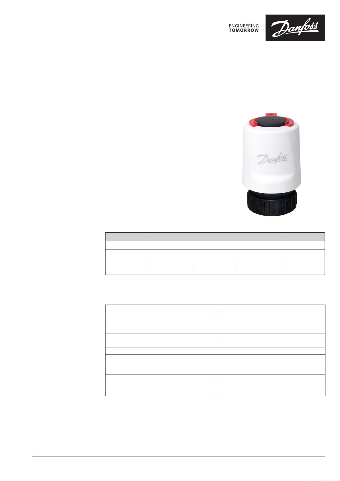
Thermot
Thermal Actuator
Application
Ordering
The thermal actuator is a small actuator for elec trical
on/off controls and PWM to activate several types
of valves and floor heating manifolds.
The actuator is equipped with a visual position
indicator to show the open or closed position of
the valve.
The product range covers actuators for 24 V (SELV)
or 230 V supply in both normally closed (NC) or
normally open (NO) versions (valve positions with
no supply voltage to the actuator).
The actuator can be connected to valves with
Heimeier/MNG/Oventrop M30×1,5 connection.
Other valves must be verified individually to ensure
correct valve closing measurement and valve top
geometry.
Actuator Connection type Supply voltage Function Code no.
Thermot M30 × 1,5* 24 V AC/DC NC 088H3216
Thermot M30 × 1,5* 24 V AC/DC NO 088H3218
Thermot M30 × 1,5* 230 V AC NC 088H3220
Thermot M30 × 1,5* 230 V AC NO 088H3222
* Connection to Heimeier, MNG and Oventrop valves with M30×1,5 connection. Other valves must be verified individu-
ally to ensure correct valve closing measurement and valve top geometr y (see “Dimensions” on page 2).
Technical Specifications
© Danfoss | FEC | 2020.07
Supply voltage 24 V (Class II (SELV**)) and 230 V (3 A pre-fuse)
Max. inrush current 24 V: 350 mA; 230 V: 250 mA
Frequency 50-60 Hz
Running power consumption 2 W
Spindle travel time ~3 min.
Ambient temperature 0 °C to 60 °C
Stroke 2,4 mm (minimum after 5 years)
Actuating force
Closing measurement 11,8 ± 0,3 mm
Approval CE
Enclosure IP 41
Cable length 950 mm
** SELV: Safety Extra Low Voltage
If the actuator should be a 24 V or 230 V and normally open (NO) or normally closed (NC) depends
mainly on the application, control strategy and the controller connected to the actuator.
NC: 100 N,
NO: 140 N
AI179686462452en-000501 | 1
Page 2
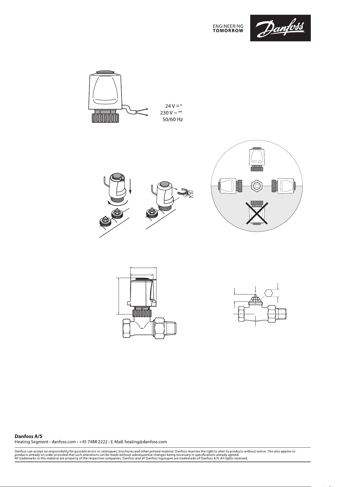
Electrical Connection
44
58
20 mm
11,8 ± 0,3 mm
A: Blue
B: Brown
Mounting
Dimensions
A
B
All NC versions are equipped with a red mounting split on the position indicator to secure easy
valve connection. When mounted this split must
be removed for correct operation.
Hand tighten only! Remove split (NC only)
38
* 24 V Class III transformer (SELV)
** 230 V max. 3 A pre-fuse
Mounting positions
2 | © Danfoss | FEC | 2020.07
AI179686462452en-000501
 Loading...