

Page 1

Fitters notes Thermostatic expansion valves
Contents Page
Introduction. . . . . . . . . . . . . . . . . . . . . . . . . . . . . . . . . . . . . . . . . . . . . . . . . . . . . . . . . . . . . . . . . . . . . . . . . . . . . . . . . . . . . . . .5
Superheat . . . . . . . . . . . . . . . . . . . . . . . . . . . . . . . . . . . . . . . . . . . . . . . . . . . . . . . . . . . . . . . . . . . . . . . . . . . . . . . . . . . . . . . . . .5
Subcooling . . . . . . . . . . . . . . . . . . . . . . . . . . . . . . . . . . . . . . . . . . . . . . . . . . . . . . . . . . . . . . . . . . . . . . . . . . . . . . . . . . . . . . . . .5
External pressure equalization . . . . . . . . . . . . . . . . . . . . . . . . . . . . . . . . . . . . . . . . . . . . . . . . . . . . . . . . . . . . . . . . . . . . . .6
Charges . . . . . . . . . . . . . . . . . . . . . . . . . . . . . . . . . . . . . . . . . . . . . . . . . . . . . . . . . . . . . . . . . . . . . . . . . . . . . . . . . . . . . . . . . . . .6
Universal charge . . . . . . . . . . . . . . . . . . . . . . . . . . . . . . . . . . . . . . . . . . . . . . . . . . . . . . . . . . . . . . . . . . . . . . . . . . . . . . . .6
MOP charge . . . . . . . . . . . . . . . . . . . . . . . . . . . . . . . . . . . . . . . . . . . . . . . . . . . . . . . . . . . . . . . . . . . . . . . . . . . . . . . . . . . .6
MOP ballast charge . . . . . . . . . . . . . . . . . . . . . . . . . . . . . . . . . . . . . . . . . . . . . . . . . . . . . . . . . . . . . . . . . . . . . . . . . . . . .7
Thermostatic expansion valve selection . . . . . . . . . . . . . . . . . . . . . . . . . . . . . . . . . . . . . . . . . . . . . . . . . . . . . . . . . . . . .7
Identication . . . . . . . . . . . . . . . . . . . . . . . . . . . . . . . . . . . . . . . . . . . . . . . . . . . . . . . . . . . . . . . . . . . . . . . . . . . . . . . . . . . . . . .7
Installation . . . . . . . . . . . . . . . . . . . . . . . . . . . . . . . . . . . . . . . . . . . . . . . . . . . . . . . . . . . . . . . . . . . . . . . . . . . . . . . . . . . . . . . . .8
Setting . . . . . . . . . . . . . . . . . . . . . . . . . . . . . . . . . . . . . . . . . . . . . . . . . . . . . . . . . . . . . . . . . . . . . . . . . . . . . . . . . . . . . . . . . . . . .9
Orice assembly replacement. . . . . . . . . . . . . . . . . . . . . . . . . . . . . . . . . . . . . . . . . . . . . . . . . . . . . . . . . . . . . . . . . . . . . 10
Danfoss product range. . . . . . . . . . . . . . . . . . . . . . . . . . . . . . . . . . . . . . . . . . . . . . . . . . . . . . . . . . . . . . . . . . . . . . . . . . . . 11
expansion valves
Thermostatic
© Danfoss A/S (AC-DSL/MWA), 10 - 2006 DKRCC.PF.000.G1.02 / 520H1459 3
Page 2

Notes
4 DKRCC.PF.000.G1.02 / 520H1459 © Danfoss A/S (AC-DSL/MWA), 10 - 2006
Page 3
Fitters notes Thermostatic expansion valves
Introduction
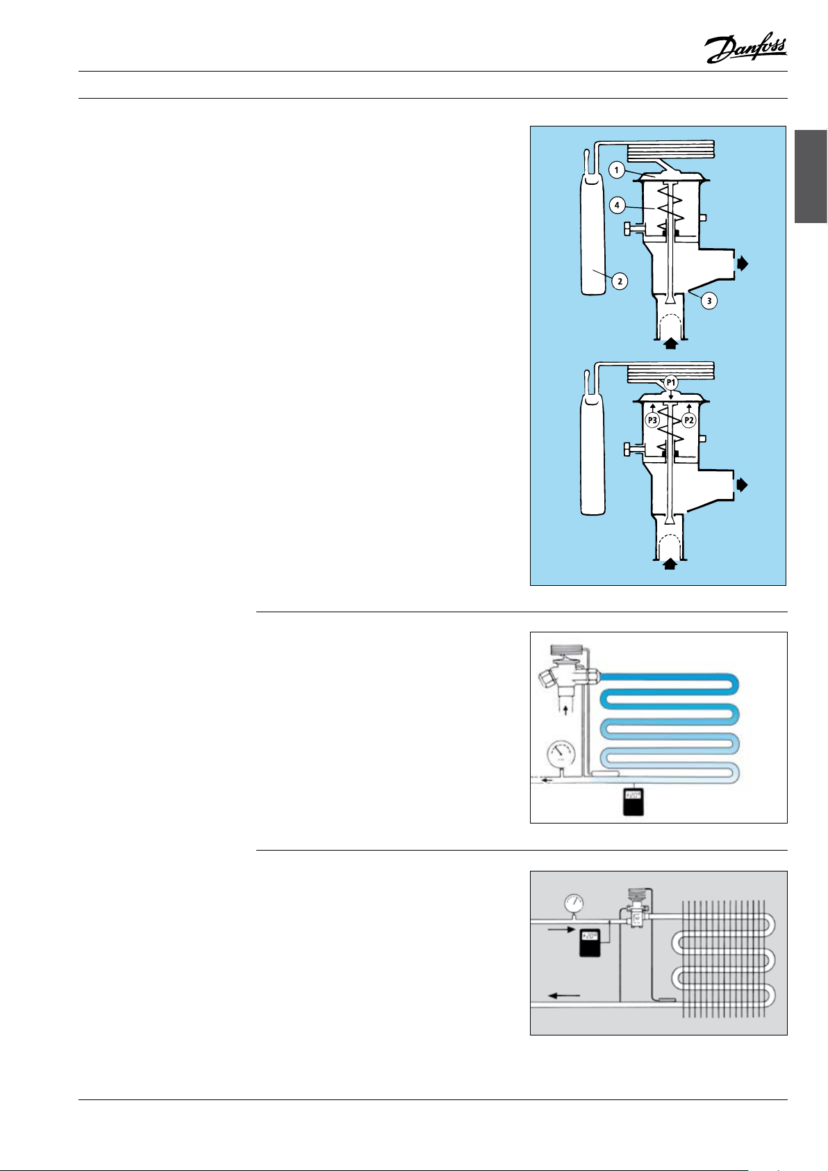
A thermostatic expansion valve is built up around
a thermostatic element (1) separated from the
valve body by a diaphragm.
A capillary tube connects the element to a bulb
(2) and a valve body with valve seat (3) and a
spring (4).
A thermostatic expansion valve works like this:
The function of a thermostatic expansion valve is
determined by three fundamental pressures:
P1: Bulb pressure which acts on the upper
surface of the diaphragm, in the valve
opening direction.
P2: Evaporating pressure which acts on the
underside of the diaphragm, in the valve
closing direction.
P3: Spring pressure which also acts on the
underside of the diaphragm, in the valve
closing direction.
When the expansion valve regulates, balance is
created between bulb pressure on one side of the
diaphragm and evaporating pressure plus spring
force on the other side.
The spring is used to set superheat.
expansion valves
Thermostatic
Superheat
Superheat is measured at the point where the
bulb is located on the suction line and is the
dierence between the temperature at the
bulb and the evaporating pressure/evaporating
temperature at the same point.
Superheat is measured in Kelvin (K) and is used as
a signal to regulate liquid injection through the
expansion valve.
Subcooling Subcooling is dened as the dierence between
condensing pressure/temperature and liquid
temperature at the expansion valve inlet.
Subcooling is measured in Kelvin (K).
Subcooling of the refrigerant is necessary to
avoid vapour bubbles in the refrigerant ahead of
the expansion valve.
Vapour bubbles in the refrigerant reduce capacity
in the expansion valve and thereby reduce liquid
supply to the evaporator.
Subcooling of 4-5K is adequate in most cases.
Ad0-0001
Ad0-0012
Ad0-0015
© Danfoss A/S (AC-DSL/MWA), 10 - 2006 DKRCC.PF.000.G1.02 / 520H1459 5
Page 4

Fitters notes Thermostatic expansion valves
External pressure
equalization
Expansion valves with external pressure equalization must always be used if liquid distributors
are installed.
Typically, the use of distributors gives a pressure
drop of 1 bar across distributor and distribution
tubes.
Expansion valves with external pressure equalization should always be used in refrigeration
systems with heavy evaporators or plate
exchangers, where normally the pressure drop
will be greater than pressure corresponding to
2K.
Charges Thermostatic expansion valves can contain one
of three dierent types of charge:
1. Universal charge
2. MOP charge
3. MOP charge with ballast, standard for Danfoss
expansion valves with MOP.
Universal charge
Expansion valves with Universal charge are used
in most refrigeration systems where there is no
pressure limitation requirement and where the
bulb can be located warmer than the element
or at high evaporating temperature/evaporating
pressure.
Ad0-0016
MOP charge
Universal charge means that there is liquid
charge in the bulb. The amount of charge is so
large that charge remains in the bulb irrespective
of whether the element is colder or warmer than
the bulb.
Expansion valves with MOP charge are typically
used on factory-made units where suction
pressure limitation on starting is required, e.g.
in the transport sector and in air conditioning
systems.
All expansion valves with MOP have a very small
charge in the bulb.
This means that the valve or the element must be
located warmer than the bulb. If it is not, charge
can migrate from the bulb to the element and
prevent the expansion valve from functioning.
MOP charge means limited liquid charge in the
bulb.
“MOP” stands for Maximum Operating Pressure
and is the highest suction pressure/ evaporating
pressure permissible in the evaporator/suction
line.
The charge will have evaporated when the
temperature reaches the MOP point. Gradually,
as the suction pressure rises, the expansion valve
begins to close at approx. 0.3/0.4 bar below the
MOP point. It becomes completely closed when
the suction pressure is the same as the MOP
point.
Ad0-0017
Ad0-0018
MOP is often called “Motor Overload Protection”.
6 DKRCC.PF.000.G1.02 / 520H1459 © Danfoss A/S (AC-DSL/MWA), 10 - 2006
Page 5

Fitters notes Thermostatic expansion valves
MOP ballast charge
Thermostatic expansion
valve selection
Expansion valves with MOP ballast charges are
used mainly in refrigeration systems with “highdynamic” evaporators, e.g. in air conditioning
systems and plate heat exchangers with high
heat transfer.
With MOP ballast charge, up to 2 - 4 K less
superheat can be obtained than with other types
of charge.
The bulb in a thermostatic expansion valve
contains a material of high porosity and large
surface area in relation to weight.
MOP charge with ballast has a damping eect on
expansion valve regulation.
The valve opens slowly as bulb temperature rises
and closes quickly as bulb temperature fails.
The thermostatic expansion valve can be selected when the following are known:
Refrigerant
Evaporator capacity
Evaporating pressure
Condensing pressure
Ad0-0021
Subcooling
Pressure drop across valve
Internal or external pressure equalization
expansion valves
Thermostatic
Identication The thermostatic element is tted with a laser
engraving on top of the diaphragm.
The code refers to the refrigerant for which the
valve is designed:
L = R410A
N = R134a
S = R404A/ R507
X = R22
Z = R407C
This engraving gives valve type (with code
number), evaporating temperature range, MOP
point, refrigerant, and max. working pressure,
PS/MWP.
With TE 20 and TE 55 the rated capacity is
stamped on a band label fastened to the valve.
The orice assembly for T2 and TE2 is marked
with the orice size (e.g. 06) and week stamp +
last number in the year (e.g. 279).
The orice assembly number is also given on the
lid of its plastic container.
On TE 5 and TE 12 the upper stamp (TE 12)
indicates for which valve type the orice can be
used. The lower stamp (01) is the orice size.
On TE 20 and TE 55 the lower stamp (50/35 TR
N/B) indicates the rated capacity in the two
evaporating temperature ranges N and B, and the
refrigerant. (50/35 TR = 175 kW in range N and
123 kW in range B).
The upper stamp (TEX 55) refers to the valve type
for which the assembly can be used.
Ad0-0019
Ad0-0023
Ad0-0020
© Danfoss A/S (AC-DSL/MWA), 10 - 2006 DKRCC.PF.000.G1.02 / 520H1459 7
Page 6

Fitters notes Thermostatic expansion valves
Installation The expansion valve must be installed in the
liquid line, ahead of the evaporator, with its
bulb fastened to the suction line as close to the
evaporator as possible.
If there is external pressure equalization, the
equalizing line must be connected to the suction
line immediately after the bulb.
The bulb is best mounted on a horizontal suction
line tube and in a position corresponding to
between 1 o’clock and 4 o’clock.
Location depends on the outside diameter of the
tube.
Note:
The bulb must never be located at the bottom
of the suction line due to the possibility of oil
laying in the bottom of the pipe causing false
signals.
The bulb must be able to sense the temperature
of the superheated suction vapour and must
therefore not be located in a position that will
expose it to extraneous heat/cold.
If the bulb is exposed to a warm air current,
insulation of the bulb is recommended.
The Danfoss bulb strap allows a tight and secure
tting of the bulb to the tube, thereby securing
that the bulb has ultimate thermal contact to
the suction tube. The TORX design of the screw
makes it easy for the tter to transfer the torque
from the tool to the screw without having to
press the tool into the screw slot. Furthermore,
with the TORX slot design, there is no risk of
damaging the screw slot.
Ad0-0002
Ad0-0003
Ad0-0004
The bulb must not be installed after a heat
exchanger because in this position it will give
false signals to the expansion valve.
Ad0-0005
The bulb must not be installed close to components of large mass as this also will give rise to
false signals to the expansion valve
Ad0-0006
8 DKRCC.PF.000.G1.02 / 520H1459 © Danfoss A/S (AC-DSL/MWA), 10 - 2006
Page 7

Fitters notes Thermostatic expansion valves
Installation (cont.)
As previously mentioned, the bulb must be
installed to the horizontal part of the suction line
immediately after the evaporator. It must not be
installed to a collection tube or a riser after an oil
pocket.
The expansion valve bulb must always be
installed ahead of any liquid lock.
Ad0-0007
expansion valves
Thermostatic
Ad0-0008
Setting The expansion valve is supplied with a factory
setting suitable for most applications.
If necessary, readjustment can be made using the
setting spindle on the valve.
Turning the spindle clockwise increases the
expansion valve superheat and turning it
counterclock-wise reduces it.
For T /TE 2, one turn of the spindle produces a
change of approx. 4K in the superheat at 0°C
evaporating temperature.
Ad0-0009
© Danfoss A/S (AC-DSL/MWA), 10 - 2006 DKRCC.PF.000.G1.02 / 520H1459 9
Page 8

Fitters notes Thermostatic expansion valves
Setting (cont.)
For TE 5 and following sizes, one turn of the
spindle produces a change of approx. 0.5K in
the superheat at 0°C evaporating temperature.
For TUA and TUB, one turn of the spindle
produces a change of approx. 3K in the superheat at 0°C evaporating temperature.
Hunting in the evaporator can be eliminated by
the following procedure:
Increase the superheat by turning the expansion
valve setting spindle well to the right (clockwise)
so that hunting stops. Then turn the setting
spindle in counter-clockwise steps so that
hunting again occurs.
From this position, turn the spindle about once
clockwise (but only 1/4 turn for T /TE 2 valves).
On this setting the refrigeration system will not
hunt and the evaporator is fully utilized.
A variation of 1 K in superheat is not regarded as
hunting.
Ad0-0010
Ad0-0011
Orice assembly
replacement
If the superheat in the evaporator is too high, the
reason might be an inadequate supply of liquid
refrigerant.
The superheat can be reduced by turning the
expansion valve setting spindle counterclockwise
in steps until hunting is observed.
From this setting, the spindle must be turned
about once clockwise (but only 1/4 turn for T/TE
2). This setting fully utilizes the evaporator.
A variation of 1 K in superheat is not regarded as
hunting.
Ad0-0013
If the evaporator continues to hunt, regardless of
the superheat setting, the valve capacity might
be too high and the orice assembly, or the valve,
needs replacing with a smaller one.
If the evaporator superheat is too high the valve
capacity is too low and the orice assembly must
be replaced with a larger one.
TE, T2, TUA, TCAE valves are supplied with an
interchangeable orice.
Ad0-0014
10 DKRCC.PF.000.G1.02 / 520H1459 © Danfoss A/S (AC-DSL/MWA), 10 - 2006
Page 9

Fitters notes Thermostatic expansion valves
Danfoss product range
Thermostatic expansion
valves
Danfoss oers a comprehensive range of
thermostatic expansion valves with capacities
from 0.4 to 1083 kW (R134a).
T/TE 2 valves have a brass housing and are/
are or solder/are connections.
Rated capacity: 0.4 - 10.5 kW (R134a).
TUA, TUB, TUC valves have a stainless steel
housing and stainless steel/copper bimetal
solder connections.
Rated capacity: 0.5 - 12 kW (R134a).
The valves can be supplied with or without
external pressure equalization.
TUA has an interchangeable orice
assembly and adjustable superheat.
TUB has a xed orice and adjustable
superheat.
TUC has a xed orice and factory set
superheat.
TUB and TUC are primarily for OEM customers.
All TUB and TUC valves can be replaced by TUA
valves.
TCAE, TCBE, TCCE valves have a stainless steel
housing and stainless steel/copper bimetal
solder connections.
Rated capacity: 12 - 18 kW (R134a).
The valves are designed as the TU valves but with
a higher capacity.
TDE valves have a brass housing and copper
solder connections.
Rated capacity: 10.5 - 140 kW (R407C)
The valves are supplied with a xed orice and
adjustable superheat.
TE 5 - TE 55 valves have a brass housing.
The valves are supplied as a part programme
consisting of valve housing, orice and thermostatic element.
The valve housing is available in a straightway
or angleway version with solder, are and ange
connections.
Rated capacity: 12.9 - 220 kW (R134a).
The valves are supplied with external pressure
equalization.
PHT 85 - 300 valves are supplied as a part
programme consisting of valve housing, anges,
orice and thermostatic element.
Rated capacity: 55 - 1083 kW (R134a).
For further information consult the internet or
the catalogue material.
expansion valves
Thermostatic
The valves are supplied with external pressure
equalization.
TRE valves have a brass housing and stainless
steel/copper bimetal connections.
Rated capacity: 18 - 196 kW (R134a).
The valves are supplied with a xed orice and
adjustable superheat.
© Danfoss A/S (AC-DSL/MWA), 10 - 2006 DKRCC.PF.000.G1.02 / 520H1459 11
Page 10

 Loading...