

Page 1
OperatingGuide
TermixVX
1.0TableofContents
1.0TableofContents.............................................1
........................................................................2
2.0Functionaldescription......................................3
3.0Safetynotes.....................................................4
3.1SafetyNotes–general............................................4
4.0Mounting........................................................5
4.1Mounting...........................................................5
4.2Start-up..............................................................7
4.3Electricalconnections.............................................9
5.0Design.............................................................10
5.1Design...............................................................10
5.2Schematicdiagram................................................11
6.0Controls..........................................................12
6.1Heatingcircuit......................................................12
6.2Other.................................................................16
6.3Maintenance........................................................18
7.0Troubleshooting..............................................19
7.1Troubleshootingingeneral......................................19
7.2TroubleshootingHE...............................................20
7.3Disposal.............................................................22
8.0Declaration......................................................23
8.1Declarationofconformity........................................23
©Danfoss|2018.12VI.CW.N5.02/LUK40300|1
Page 2

OperatingGuideTermixVX
2|©Danfoss|2018.12
VI.CW.N5.02/LUK40300
Page 3

OperatingGuideTermixVX
2.0Functionaldescription
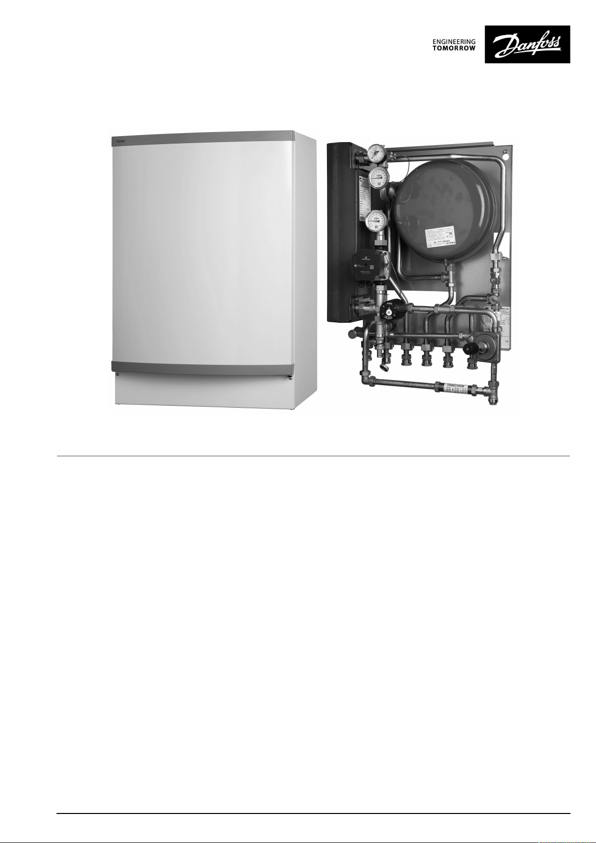
Districtheatingsubstationforindirectheating.Designedfor
wall-mounting.
Application
TheTermixVXisacompletesolutionforspaceheatingwithoptimal
safety,efficientenergytransfer,service-friendlyconstructionand
acompactdesign.Thesubstationisusedifaheatexchangeris
requiredoronaconversiontodistrictheatingwheretheexisting
equipmentisunsuitablefordirectconnection.TheT ermixVX
substationisideal,whenahighlevelofsecurityagainstburstpipes
andwaterdamageintheheatingsystemisrequired.
Districtheating(DH)
Thesubstationisprefabricatedwithadifferentialpressure
controller,fittingpieceandsensorpocketsforinsertionofaheat
meteraswellasstrainersandballvalves.
Heating(HE)
Theheatingsideconsistsofastainlesssteelplateheatexchanger,
safetyvalve,manometer,thermometers,ballvalves,drainvalve,air
valve,expansionvesselandcirculationpump.Thetemperature
oftheheatingcanbecontrolledthermostaticallyorbyan
electronictemperaturecontrollerwithanoutdoortemperature
sensor.Dependingontheapplication,differentheatexchangers
dimensionedforcentralorfloorheatingcanbeused.Asanoption
thesubstationcanbeequippedwithathermostatwithsafety
monitor.Thisispossibleonlyforsubstationswithelectronic
temperaturecontroller.
Domestichotwater(DHW)
Thesubstationcanbesuppliedwithconnectionpipesforahot
watertankontheprimaryorthesecondarysideoftheheat
exchanger.
VI.CW.N5.02/LUK40300
©Danfoss|2018.12|3
Page 4
OperatingGuideTermixVX
3.0Safetynotes
3.1SafetyNotes–general
Thefollowinginstructionsrefertothestandarddesignof
substation.Specialversionsofsubstationsareavailableon
request.
Thisoperatingmanualshouldbereadcarefullybeforeinstallation
andstart-upofthesubstation.Themanufactureracceptsno
liabilityfordamageorfaultsthatresultfromnon-compliancewith
theoperatingmanual.Pleasereadandfollowalltheinstructions
carefullytopreventaccidents,injuryanddamagetoproperty.
Assembly,start-upandmaintenanceworkmustbeperformedby
qualifiedandauthorizedpersonnelonly.
Pleasecomplywiththeinstructionsissuedbythesystem
manufacturerorsystemoperator.
Corrosionprotection
Allpipesandcomponentsaremadeofstainlesssteelandbrass.
Themaximumchloridecompoundsoftheflowmediumshouldnot
behigherthan150mg/l.
Theriskofequipmentcorrosionincreasesconsiderablyifthe
recommendedlevelofpermissiblechloridecompoundsis
exceeded.
Energysource
Thesubstationisdesignedfordistrictheatingastheprimary
sourceofenergy.However,alsootherenergysourcescanbeused
wheretheoperatingconditionsallowitandalwaysarecomparable
todistrictheating.
Application
Thesubstationisdesignedtobeconnectedtothehouse
installationinafrost-freeroom,wherethetemperaturedoesnot
exceed50°Candthehumiditydoesnotexceed60%.Donotcover
orwallupthesubstationorinanyotherwayblocktheentrance
tothestation.
Authorizedpersonnelonly
Assembly,start-upandmaintenanceworkmustbeperformedby
qualifiedandauthorizedpersonnelonly.
Pleaseobserveinstructionscarefully
Toavoidinjurytopersonsanddamagetothedevice,itisabsolutely
necessarytoreadandobservetheseinstructionscarefully.
Warningofhighpressureandtemperature
Beawareoftheinstallation’spermissiblesystempressureand
temperature.
Themaximumtemperatureoftheflowmediuminthesubstationis
120°C.
Themaximumoperatingpressureofthesubstationis10bar.PN16
versionsareavailableonenquiry.
Theriskofpersonsbeinginjuredandequipmentdamagedincreases
considerablyiftherecommendedpermissibleoperatingparameters
areexceeded.
Thesubstationinstallationmustbeequippedwithsafetyvalves,
however,alwaysinaccordancewithlocalregulations.
Choiceofmaterial
Choiceofmaterialsalwaysincompliancewithlocallegislation.
Safetyvalve(s)
Werecommendmountingofsafetyvalve(s),however,alwaysin
compliancewithlocalregulations.
Connection
Thesubstationmustbeequippedwithfeaturesthatensurethat
thesubstationcanbeseparatedfromallenergysources(also
powersupply).
Emergency
Incaseofdangeroraccidents-fire,leaksorotherdangerous
circumstances-interruptallenergysourcestothestationif
possible,andseekexperthelp.
Incaseofdiscolouredorbad-smellingdomestichotwater,closeall
shut-offvalvesonthesubstation,informtheoperatingpersonnel
andcallforexperthelpimmediately.
REACH
AllDanfossA/SproductsfulfilltherequirementsinREACH.
OneoftheobligationsinREACHistoinformcustomersabout
presenceofCandidatelistsubstancesifany,weherebyinform
youaboutonesubstanceonthecandidatelist:Theproduct
containsbrasspartswhichcontainslead(CASno:7439-92-1)ina
concentrationabove0.1%w/w.
Storage
Anystorageofthesubstationwhichmaybenecessarypriorto
installationshouldbeinconditionswhicharedryandheated.
Warningofhotsurface
Thesubstationhasgothotsurfaces,whichcancauseskinburns.
Pleasebeextremelycautiousincloseproximitytothesubstation.
Powerfailurecanresultinthemotorvalvesbeingstuckinopen
position.Thesurfacesofthesubstationcangethot,whichcancause
skinburns.Theballvalvesondistrictheatingsupplyandreturnshould
beclosed.
Warningoftransportdamage
Beforesubstationinstallation,pleasemakesurethatthesubstation
hasnotbeendamagedduringtransport.
IMPORTANT-Tighteningofconnections
Duetovibrationsduringtransportallflangeconnections,screwjoints
andelectricalclampandscrewconnectionsmustbecheckedand
tightenedbeforewaterisaddedtothesystem.Afterwaterhasbeen
addedtothesystemandthesystemhasbeenputintooperation,
re-tightenALLconnections.
4|©Danfoss|2018.12
VI.CW.N5.02/LUK40300
Page 5

OperatingGuideTermixVX
4.0Mounting
4.1Mounting
Installationmustbeincompliancewithlocalstandardsand
regulations.
Districtheating(DH)-Inthefollowingsections,DHreferstothe
heatsourcewhichsuppliesthesubstations.Avarietyofenergy
sources,suchasoil,gasorsolarpower,couldbeusedasthe
primarysupplytoDanfosssubstations.Forthesakeofsimplicity,
DHcanbetakentomeantheprimarysupply.
Connections:
1.Districtheating(DH)supply
2.Districtheating(DH)return
3.Heating(HE)supply
4.Heating(HE)return
5.Tankflowline(TFL)
6.Tankreturnline(TRL)
Authorizedpersonnelonly
Assembly,start-upandmaintenanceworkmustbeperformedby
qualifiedandauthorizedpersonnelonly.
Connectionsizes:
DH+HE:
TFL+TRL:
Dimensions(mm):
Withoutcover:
Withcover:
Weight(approx.):30kg
Thepipeplacementcandeviatefromtheshowndrawing.Pleasenote
themarkingsonthestation.
G¾”(int.thread)
G¾”(int.thread)
H750xW505xD360
H800xW540xD430
VI.CW.N5.02/LUK40300
©Danfoss|2018.12|5
Page 6

OperatingGuideTermixVX
4.1.1Installation
Mounting:
Adequatespace
Pleaseallowadequatespacearoundthesubstationformounting
andmaintenancepurposes.
Orientation
Thestationmustbemountedsothatcomponents,keyholes
andlabelsareplacedcorrectly.Ifyouwishtomountthestation
differentlypleasecontactyoursupplier.
Drillings
Wheresubstationsaretobewall-mounted,drillingsareprovided
inthebackmountingplate.Floormountedunitshavesupport.
Labelling
Eachconnectiononthesubstationislabelled.
Beforeinstallation:
Cleanandrinse
Priortoinstallation,allsubstationpipesandconnectionsshouldbe
cleanedandrinsed.
Keyholeformounting.
Tightening
Duetovibrationduringtransport,allsubstationconnectionsmust
becheckedandtightenedbeforeinstallation.
Unusedconnections
Unusedconnectionsandshut-offvalvesmustbesealedwitha
plug.Shouldtheplugsrequireremoval,thismustonlybedoneby
anauthorizedservicetechnician.
Installation:
Strainer
Ifastrainerissuppliedwiththestationitmustbefittedaccording
toschematicdiagram.Pleasenotethatthestrainermaybe
suppliedloose.
Connections
Internalinstallationanddistrictheatingpipesconnectionsmustbe
madeusingthreaded,flangedorweldedconnections.
6|©Danfoss|2018.12
VI.CW.N5.02/LUK40300
Page 7
OperatingGuideTermixVX
4.2Start-up
Start-up,Indirectheating
Filling:
1:Firstfill
Whencarryingoutfirstfill,theheatexchangermustbeslowlyfilled
withwateruntilitreachesworkingpressure.
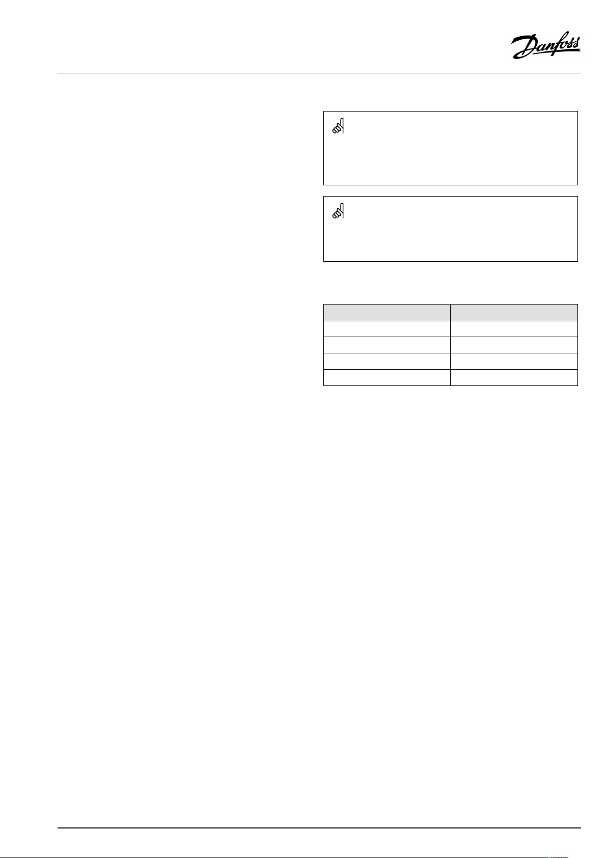
2:Pressuregauge
TheHEpressuregaugeindicatesthepressureoftheHEsystem.This
instructionmustbefollowedstrictly,toavoiddangeroussituations.
3:Supplyhose
AballvalvewithplugisinstalledintheHEreturnline.Tofillthe
system,theballvalvemustfirstbeclosed,theplugremovedand
asupplyhoseconnected.Onre-openingtheballvalve,system
fillcancommence.
4:Pre-pressure
Whenfillingthesystemwithwater,thepressuregaugeshouldbe
observedclosely.Theexpansionvesselissuppliedpre-pressurised
to0.5bar.Thepre-pressurerequiredateachsubstationwill
dependonsystemhead(thedistancebetweenthelowestand
highestpointinthesystem),forexample:
5:Fillingstop
Fillingmuststopwhenthepressuregaugeshowsapressure
approximately1-2barhigherthanthepre-pressuresetting.The
ballvalveisthenclosed,thehoseremovedandtheplugputback
in.
Re-tightenconnections
Afterwaterhasbeenaddedtothesystemandthesystemhasbeen
putintooperation,re-tightenALLconnections.
Pump
Thepumpmustbeswitchedoffduringsystemfill.
Height(m)Pressure(bar)
0–50,5
5–101,0
10–15
1,5
15–202,0
Start-up:
1:Pumpspeed
Setthepumptohighestspeedbeforestart-up.
2:Startpump
Startthepumpandheatthroughthesystem.
3:Openshut-offvalves
Theshut-offvalvesshouldthenbeopenedandtheunitobserved
asitentersservice.Visualcheckingshouldconfirmtemperatures,
pressures,acceptablethermalexpansionandabsenceofleakage.
Iftheheatexchangeroperatesinaccordancewithdesign,itcanbe
puttoregularuse.
4:Ventsystem
Switchoffthepumpandventtheinstallationaftertheradiators
havebeenwarmedup.
5:Adjustpumpspeed
Setthepumptothelowestspeedconsistentwithcomfortand
electricityconsumption.
Normallythechange-overswitchissetinthemidposition(default).
Howeverforsystemswithunderfloorheatingorsinglepipeloop
systems,itmaybenecessarytoturnthechange-overswitch
upwards.
Higherpumpspeedsareonlyusediftheheatingrequirement
increases.
VI.CW.N5.02/LUK40300
©Danfoss|2018.12|7
Page 8

OperatingGuideTermixVX
Underfloorheating:
Pumpstopfunction
Ifthesubstationisusedinconnectionwithunderfloorheating,the
circulationpumpmustbeconnectedtothepumpstopfunctionin
theunderfloorheatingcontroller.Thepumpmustbestoppedif
allunderfloorheatingcircuitsareclosed.
Warranty
Ifthisisnotpossible,thenflowmustbecontinuedthroughthe
by-pass.Failingthis,thepumpwillbeatriskofseizureandany
remainingwarrantywillbewithdrawn.
Summeroperation:
Switchoffpump
Insummerthecirculationpumpmustbeswitchedoffandthe
shut-offvalvetoHEsupplyclosed.
Runningpumpbi-weekly
Itisrecommendedtostartupthecirculationpump(for2minutes)
onceamonthduringsummer;theshut-offvalveoftheHEsupply
mustbeshut.
Electroniccontroller
Mostelectroniccontrollerswillstartupthepumpautomatically
(pleasenotemanufacturer´sinstructions).
8|©Danfoss|2018.12
VI.CW.N5.02/LUK40300
Page 9

OperatingGuideTermixVX
4.3Electricalconnections
Beforemakingelectricalconnections,pleasenotethe
following:
Safetynotes
Pleasereadtherelevantpartsofthesafetynotes.
230V
Thesubstationmustbeconnectedto230VACandearth.
Potentialbonding
Potentialbondingshouldbecarriedoutaccording
to60364-4-41:2007andIEC60364-5-54:2011.
Bondingpointonthemountingplatebelowrightcornermarked
withearthsymbol.
Disconnection
Thesubstationmustbeelectricallyconnectedsothatitcanbe
disconnectedforrepairs.
Outdoortemperaturesensor
Outdoorsensorsshouldbemountedsoastoavoidexposureto
directsunlight.Theyshouldnotbeplacedclosetodoors,windows
orventilationoutlets.
Theoutdoorsensormustbeconnectedtothestationonthe
terminalblockundertheelectroniccontrol.
Authorizedelectrician
Electricalconnectionsmustbemadebyanauthorizedelectricianonly.
Localstandards
Electricalconnectionsmustbemadeinaccordancewithcurrent
regulationsandlocalstandards.
VI.CW.N5.02/LUK40300
©Danfoss|2018.12|9
Page 10

OperatingGuideTermixVX
5.0Design
5.1Design
Yoursubstationmightlookdifferentthanthesubstationshown.
Designdescription
A
Heatexchanger,HE
1A
Summervalve
4
Safetyvalve,HE
7
Thermostaticcontroller,HE
9
Strainer
10|©Danfoss|2018.12
10
Circulatorpump
14
Sensorpocket,energymeter
20
Filling/drainvalve
26
Pressuregauge,HE
31
Differentialpressurecontroller
38
Expansiontank
41
Fittingpiece,energymeter
48
Airvent,manual
VI.CW.N5.02/LUK40300
Page 11

OperatingGuideTermixVX
5.2Schematicdiagram
DH
Supply
DH
Return
TRL
TFL
Yoursubstationmightlookdifferentthantheschematicdiagramshown.
Schematicdescription
A
Heatexchanger,HE
1
Ballvalve
4
Safetyvalve
7
Thermostaticvalve,HE
9
Strainer
10
Circulationpump
18
Thermometer
20
Filling/drainvalve
24
Deliveredloosewithunit
26
Pressuregauge
31
Differentialpressurecontroller
38
Expansiontank
41
Fittingpiece,energymeter
48
Airvent,manual
HE
Supply
HE
Return
DHSupply:DistrictHeatingSupply
DHReturn:DistrictHeatingReturn
HESupply:HeatingSupply
HEReturn:HeatingReturn
TFL:
TRL:
5.2.1Technicalparameters
Technicalparameters
Nominalpressure:PN10(PN16versionsareavailableonenquiry)
Max.DHsupplytemperature:
Min.DCWstaticpressure:
Brazingmaterial(HEX):
Heatexchangerstestpressure:30bar
Soundlevel:≤55dB
TankFlowLine
TankReturnLine
120°C
0.5bar
Copper
VI.CW.N5.02/LUK40300
©Danfoss|2018.12|11
Page 12

OperatingGuideTermixVX
6.0Controls
6.1Heatingcircuit
6.1.1Differentialpressurecontroller
Thedifferentialpressurecontrollersmoothsoutthefluctuationsin
pressurearrivingfromthedistrictheatingnetwork.Theoperating
pressureinthesubstationisthusheldsteady.
6.1.2HEtemperaturecontrol
TheHEflowtemperatureintheheatingcircuitiscontrolledbythe
HEtemperaturecontroller.
6.1.3RAVKcontroller
RAVKcontroller(25-65°C).Thetemperaturesettingisasfollows:
1=25°C
2=35°C
3=45°C
4=55°C
5=65°C
Thevaluesareintendedasaguide.
Thermostaticcontrol
ThetemperatureoftheHEflowlineisadjustedasfollows:
Toincreasetemperature,turnthehandleonthethermostatic
controllertoselectahighernumber.
Todecreasetemperature,turnthehandleonthethermostatic
controllertoselectalowernumber.
12|©Danfoss|2018.12
VI.CW.N5.02/LUK40300
Page 13

OperatingGuideTermixVX
6.1.4AVTBcontroller(30–100°)
Thetemperaturesettingisasfollows:
1=35°C
2=55°C
3=75°C
4=95°C
5=100°C
Thevaluesareintendedasaguide.
Thermostaticcontrol
ThetemperatureoftheHEflowlineisadjustedasfollows:
Toincreasetemperature,turnthehandleonthethermostatic
controllertoselectahighernumber.
Todecreasetemperature,turnthehandleonthethermostatic
controllertoselectalowernumber.
6.1.5Flowcontrollerwithintegratedcontrolvalve
Thecontrollerisaself-actingflowcontrollerwithintegratedcontrol
valve.Thecontrollercloseswhensetmax.flowisexceededand
canbeusedincombinationwithDanfosselectricalactuatorswith
orwithoutsafetyfunction.Springreturnmotorcanbeusedas
safetyfunctionbypowerfailure.
6.1.6Electroniccontrol
Substationswithelectroniccontrolmustbesetinaccordancewith
manufacturer´sinstructions.
Wheretheroomtemperatureiscontrolledbyradiatorthermostats,
itisrecommendedthatthermostatsbesetforminimum
temperatureineachroom.
VI.CW.N5.02/LUK40300
©Danfoss|2018.12|13
Page 14

OperatingGuideTermixVX
6.1.7Outdoortemperaturesensor(ESMT)
Outdoorsensorsshouldbemountedsoastoavoidexposureto
directsunlight.Theyshouldnotbeplacedclosetodoors,windows
orventilationoutlets.
6.1.8CirculatorpumpUPM3
UPM3Pumpscanbecontrolledinconstantpressure,proportional
pressureorconstantspeedmodedefinedbythemeansofasmart
userinterface.
Thevariablespeedmodulatingmodesallowthepumptomatchits
performancetothesystemrequirements,helpingtoreducenoise
whenthermostaticvalvesareclosingdown.
EnergylabellingclassA
14|©Danfoss|2018.12
VI.CW.N5.02/LUK40300
Page 15
OperatingGuideTermixVX
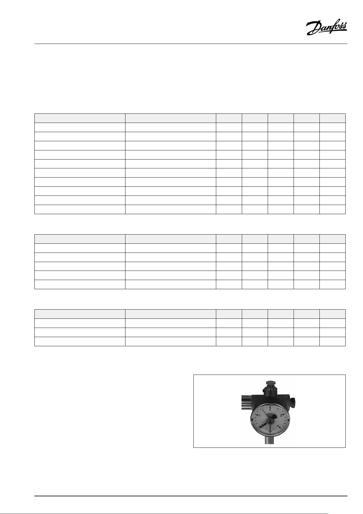
6.1.9GrundfosUPM3AUTOLinstructions
Controlmode
Youcanswitchfromtheperformanceviewtothesettingsviewbypressingthepushbutton.Thesettingsviewshowswhichmode
controlsthecirculator.After2seconds,thedisplayswitchesbacktoperformanceview.
Ifyoupressthebuttonfor2to10seconds,theuserinterfaceswitchesto"settingselection"iftheuserinterfaceisunlocked.Youcan
changethesettingsastheyappear.Theselectionofthecontrolmodedependsonthesystemtypeandtheallocationofpressurelosses.
Ifyoupressthekeylockformorethan10seconds,youcantogglebetweenenabling/disablingthekeylockfunction.
Function
Proportionalpressure1
Proportionalpressure2
Proportionalpressure3
Constantpressure1
Constantpressure2
Constantpressure3
ConstantCurve1
ConstantCurve2
ConstantCurve3
ConstantCurveMax.
Operationstatus
Function
Standby**OnlyPWMcontrolled
0%≤P1≤25%
25%≤P1≤50%
50%≤P1≤75%
75%≤P1≤100%
Recommendedfor
2-pipesystems
1-pipesystems
Underfloorheating
Green
✪✪
✪✪✪
✪✪✪✪
✪✪
✪✪✪
✪✪✪✪
✪✪✪
✪✪✪✪
✪✪✪✪✪
✪✪✪✪
Green
✪
✪✪
✪✪✪
✪✪✪✪
✪✪✪✪✪
YellowYellowYellowYellow
YellowYellowYellowYellow
Alarmstatus
Function
Blocked
Supplyvoltagelow
Electricalerror
6.1.10HEpressuregauge
TheHEpressuregaugeindicatesthepressureoftheHEsystem.
RedYellowYellowYellowYellow
✪✪
✪✪
✪✪
VI.CW.N5.02/LUK40300
©Danfoss|2018.12|15
Page 16

OperatingGuideTermixVX
6.2Other
6.2.1Safetyvalve
Thepurposeofthesafetyvalveistoprotectthesubstationfrom
excessivepressure.
Theblow-offpipefromthesafetyvalvemustnotbeclosed.The
blow-offpipeoutletshouldbeplacedsothatitdischargesfreely
anditispossibletoobserveanydrippingfromthesafetyvalve.
Itisrecommendedtochecktheoperationofsafetyvalvesat
intervalsof6months.Thisisdonebyturningthevalveheadin
directionindicated.
6.2.2Strainer
Strainersshouldbecleanedregularlybyauthorizedpersonnel.The
frequencyofcleaningwoulddependonoperatingconditionsand
themanufacturer’sinstructions.
16|©Danfoss|2018.12
VI.CW.N5.02/LUK40300
Page 17

OperatingGuideTermixVX
6.2.3Fittingpiece
Thesubstationisequippedwithafittingpieceforenergymeter.
Assemblyofenergymeters:
1:Closeballvalves
ClosetheballvalvesonDHSupplyandDHReturn,ifthereiswater
onthesystem.
2:Loosennuts
Loosenthenutsonthefittingpiece.
3:Removefittingpiece
Removethefittingpieceandreplaceitwiththeenergymeter.Do
notforgetthegaskets.
4:Tightenconnections
Aftermountingoftheenergymeterremembertocheckand
tightenallthreadedconnections.
Sensorpocket,energymeter
Thesensorsoftheenergymeterismountedinthesensorpockets.
VI.CW.N5.02/LUK40300
©Danfoss|2018.12|17
Page 18

OperatingGuideTermixVX
6.3Maintenance
Thesubstationrequireslittlemonitoring,apartfromroutine
checks.Itisrecommendedtoreadtheenergymeteratregular
intervals,andtowritedownthemeterreadings.
RegularinspectionsofthesubstationaccordingtothisInstruction
arerecommended,whichshouldinclude:
Strainers
Cleaningofstrainers.
Meters
Checkingofalloperatingparameterssuchasmeterreadings.
Temperatures
Checkingofalltemperatures,suchasDHsupplytemperatureand
DHWtemperature.
Connections
Checkingallconnectionsforleakages.
Safetyvalves
Theoperationofthesafetyvalvesshouldbecheckedbyturning
thevalveheadintheindicateddirection.
Venting
Checkingthatthesystemisthoroughlyvented.
Authorizedpersonnelonly
Assembly,start-upandmaintenanceworkmustbeperformedby
qualifiedandauthorizedpersonnelonly.
Inspectionsshouldbecarriedoutminimumeverytwoyears.
SparepartscanbeorderedfromDanfoss.Pleaseensurethatany
enquiryincludesthesubstationserialnumber.
18|©Danfoss|2018.12
VI.CW.N5.02/LUK40300
Page 19

OperatingGuideTermixVX
7.0Troubleshooting
7.1Troubleshootingingeneral
Intheeventofoperatingdisturbances,thefollowingbasicfeatures
shouldbecheckedbeforecarryingoutactualtroubleshooting:
•thesubstationisconnectedtoelectricity,
•thestrainerontheDHsupplypipeisclean,
•thesupplytemperatureoftheDHisatthenormallevel
(summer,atleast60°C-winter,atleast70°C),
•thedifferentialpressureisequaltoorhigherthanthenormal
(local)differentialpressureintheDHnetwork–ifindoubt,ask
theDHplantsupervisor,
•pressureonthesystem-checktheHEpressuregauge.
Authorizedpersonnelonly
Assembly,start-upandmaintenanceworkmustbeperformedby
qualifiedandauthorizedpersonnelonly.
VI.CW.N5.02/LUK40300
©Danfoss|2018.12|19
Page 20

OperatingGuideTermixVX
7.2TroubleshootingHE
ProblemPossiblecauseSolution
Toolittleornoheat.StrainercloggedinDHorHEcircuit
Unevenheatdistribution.Airpocketsinthesystem.Venttheinstallationthoroughly.
DHsupplytemperaturetoohigh.
DHsupplytemperaturetoolow.
(radiatorcircuit).
ThefilterintheenergymeteronDHcircuit
clogged.
Defectiveorwronglyadjusteddifferential
pressurecontroller.
Sensordefective–orpossiblydirtinthe
valvehousing.
Automaticcontrols,ifany,wronglysetor
defective-possiblypowerfailure.
Pumpoutofoperation.Checkifthepumpisreceivingpowerand
Thepumpissetattoolowspeedof
rotation.
Pressuredrop–thepressuredropon
theradiatorcircuitshowslowerthan
recommendedoperatingpressure.
Airpocketsinthesystem.Venttheinstallationthoroughly.
Limitingofthereturntemperatureadjusted
toolow.
Defectiveradiatorvalves.
Unevenheatdistributioninbuilding
becauseofincorrectlysetbalancingvalves,
orbecausetherearenobalancingvalves.
Diameterofpipetosubstationtoosmallor
branchpipetoolong.
Wrongsettingofthermostatorof
automaticcontrols,ifany.
Defectivecontroller.Thecontrollerdoes
notreactasitshouldaccordingtothe
instructions.
Defectivesensoronself-actingthermostat.
Wrongsettingofautomaticcontrols,ifany.
Defectivecontroller.Thecontrollerdoes
notreactasitshouldaccordingtothe
instructions.
Defectivesensoronself-actingthermostat.
Wrongplacement/fittingofoutdoor
temperaturesensor.
Strainerclogged.Cleangate/strainer.
Cleangate/strainer(s).
Cleanthefilter(afterconsultingtheDH
plantoperator).
Checktheoperationofthedifferential
pressurecontroller–cleanthevalveseatif
required.
Checktheoperationofthethermostat–
cleanthevalveseatifrequired.
Checkifthesettingofthecontroller
iscorrect–seeseparateinstructions.
Checkthepowersupply.Temporary
settingofmotorto“manual”control–see
instructionsonautomaticcontrols.
thatitturns.Checkifthereisairtrappedin
thepumphousing–seepumpmanual.
Setthepumpathigherspeedofrotation.
Fillwateronthesystemandcheckthe
functioningofthepressureexpansion
vesselifrequired.
Adjustaccordingtoinstructions.
Check–replace.
Adjust/installbalancingvalves.
Checkpipedimensions.
Adjustautomaticcontrols,–see
instructionsforautomaticcontrols.
Callautomaticcontrolsmanufactureror
replacetheregulator.
Replacethermostat–orsensoronly.
Adjustautomaticcontrols–seeinstructions
forautomaticcontrols.
Callinautomaticcontrolsmanufactureror
replacecontroller.
Replacethermostat–orsensoronly.
Adjustlocationofoutdoortemperature
sensor.
20|©Danfoss|2018.12
VI.CW.N5.02/LUK40300
Page 21

OperatingGuideTermixVX
ToohighDHreturntemperature.
Noiseinsystem.
Heatloadtoohigh.
Toosmallheatingsurface/toosmall
radiatorscomparedtothetotalheating
requirementofthebuilding.
Poorutilizationofexistingheatingsurface.
Defectivesensoronself-actingthermostat.
Thesystemissinglepipeloop.
Pumppressuretoohigh.Adjustpumptoalowerlevel.
Airinsystem.
Defectiveorincorrectlysetradiatorvalve(s).
Singlepipeloopsystemsrequirespecial
one-piperadiatorvalves.
Dirtinthemotorizedvalveorinthe
differentialpressurecontroller.
Defectivemotorizedvalve,sensoror
automaticcontroller.
Electroniccontrollernotadjustedcorrectly.Adjustaccordingtoinstructions.
Pumppressuretoohigh.Adjustpumptoalowerlevel.
Defectivemotorizedvalve,sensoror
electroniccontroller.
Increasetotalheatingsurface.
Makesuretheheatisdistributedevenly
acrossthefullheatingsurface–openall
radiatorsandkeeptheradiatorsinthe
systemfromheatingupatthebottom.It
isextremelyimportanttokeepthesupply
temperaturetotheradiatorsaslowas
possible,whilemaintainingareasonable
levelofcomfort.
Thesystemshouldfeatureelectronic
controlsaswellasreturnsensors.
Ventthesystem.
Check–set/replace.
Check–cleanout.
Check–replace.
Check–replace.
VI.CW.N5.02/LUK40300
©Danfoss|2018.12|21
Page 22
OperatingGuideTermixVX
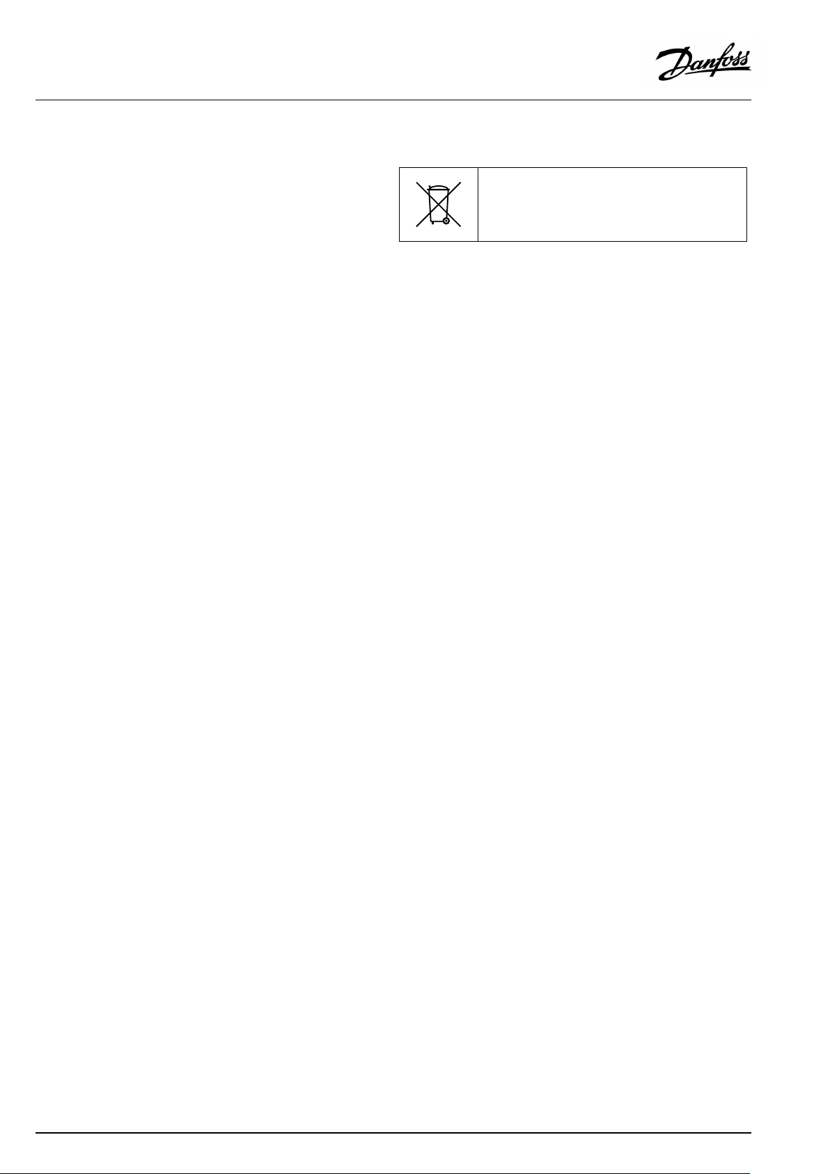
7.3Disposal
Disposal
Thisproductshouldbedismantledanditscomponents
sorted,ifpossible,invariousgroupsbeforerecycling
ordisposal.
Alwaysfollowthelocaldisposalregulations.
22|©Danfoss|2018.12
VI.CW.N5.02/LUK40300
Page 23

OperatingGuideTermixVX
8.0Declaration
8.1Declarationofconformity
Category0withelectricalequipment
VI.CW.N5.02/LUK40300
©Danfoss|2018.12|23
Page 24
OperatingGuideTermixVX
24|©Danfoss|2018.12
VI.CW.N5.02/LUK40300
 Loading...