

Page 1
Data sheet
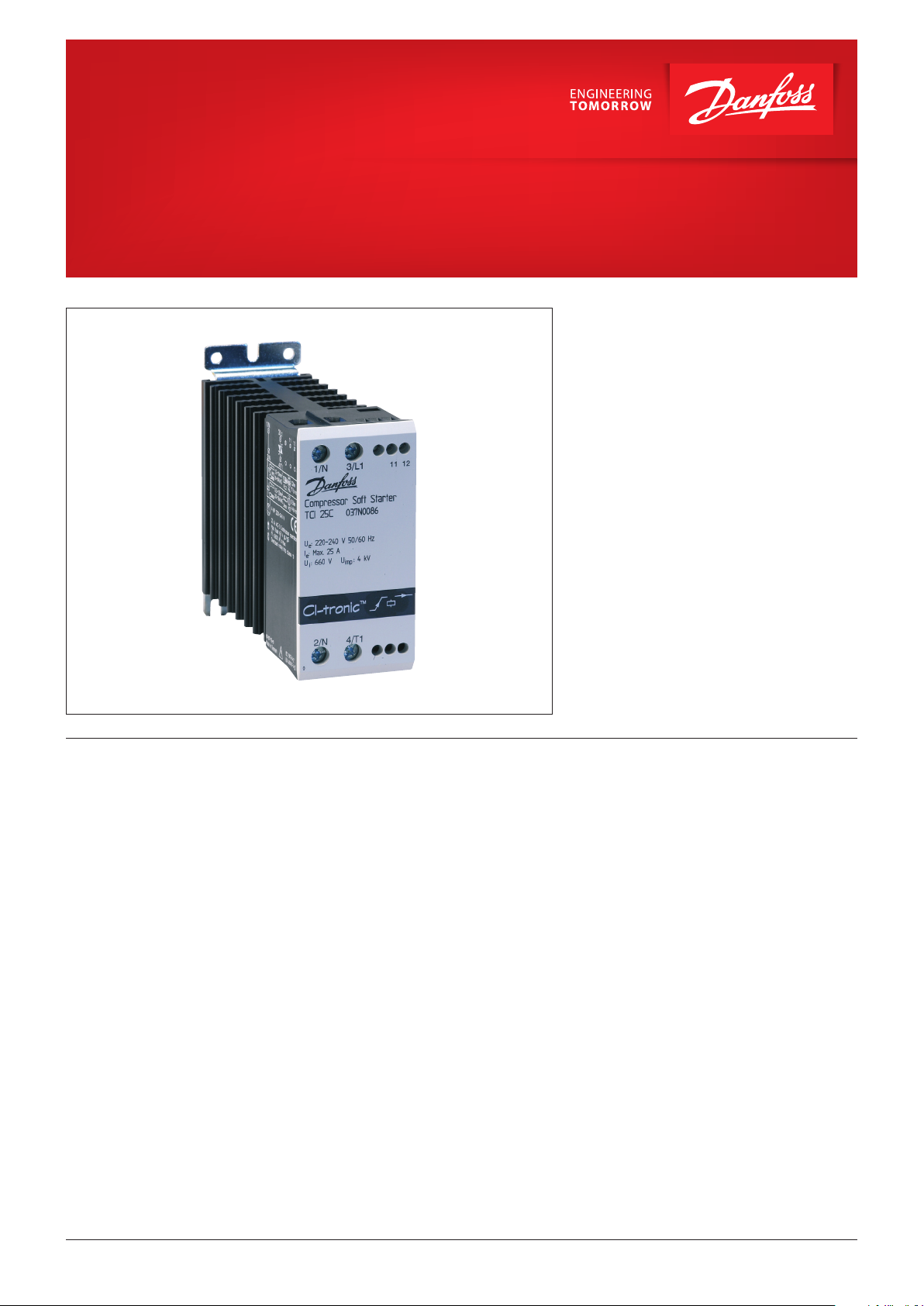
CI-tronic™ single-phase compressor soft starter,
Type TCI 25C
The TCI 25C soft starter is designed for soft
starting of single-phase compressors. During
start the TCI 25C will gradually ramp-up the
motor voltage to full line voltage thus reducing
the starting current peak.
Features • Easy installation between normal motor starter
and motor
• LED status indication
• Unlimited start/stop operation per hour
• DIN rail mountable
• Starting time max. 0,5 seconds
• Suitable for 50/60 Hz
• EN 60947-4-2
• CE, EAC, LLC CDC TYSK
© Danfoss | DCS (az) | 2018.03
IC.PD.C50.I2.02 | 1
Page 2
Data sheet | CI-tronic™ single-phase compressor soft starter, Type TCI 25C
Ordering
Technical Data
Type
TCI 25C 220 – 240 25 4.0 / 5.5 037N0086
Output specications
Operational voltage 220 – 240 V AC
Operational current (AC-3, AC-53a) 25 A max. (50 mA min.)
Semiconductor protection fusing
Type 1 co-ordination: 100 A gL/gG
Type 2 co-ordination: 6300 A2s
Control specications
EMC immunity Meets EN 60947-4-2
Start prole
Ramp-up time 0,5 seconds (max.)
Starting torque 50% of nominal starting torque
Insulation specications
Rated insulation voltage, U
Rated impulse withstand voltage, U
Installation category III
Line Voltage
[V AC] [A] [kW / HP]
i
imp
Motor Current
max.
660 V
4 kV
Motor Power
Code no.
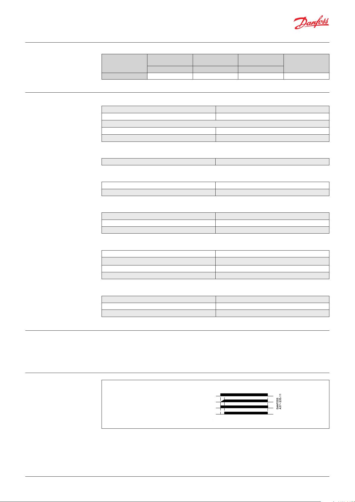
Functional description
Functional diagram
Thermal specications, environment
Power dissipation, continuously duty 1 W/A
Power dissipation, intermittent duty 1 W/A x duty cycle
Operating temperature range -5 °C – 40 °C*
Cooling method Natural convection
Materials
Housing Self extinguishing PPO UL94V1
Heat sink Aluminium black anodised
Base Electroplated steel
As soon as the TCI 25C is connected to mains
voltage a motor soft start is performed.
The balanced ramp-up time and starting voltage
TCI 25C can be used for single phase motors
with and without a start capacitor - see wiring
examples.
(initial torque) ensures a fast and reliable start.
Line voltage (L, N)
Motor voltage (T, N)
LED 1
LED 2
© Danfoss | DCS (az) | 2018.03
IC.PD.C50.I2.02 | 2
Page 3

Data sheet | CI-tronic™ single-phase compressor soft starter, Type TCI 25C
Wiring examples
Single-phase motor without a start capacitor Single-phase motor with a start capacitor
Operating at high
temperatures
For selection of capacitors and start relay, please refer to recommendations from the compressor
manufacturer
If the ambient temperature exceeds 40 °C the current must be de-rated according to table below.
Ambient temperature Continuous current Intermittent current (max. 15 min. ON-time)
50 °C 23 A 25 A (max. duty cycle 0.8)
60 °C 15 A 25 A (max. duty cycle 0.65)
© Danfoss | DCS (az) | 2018.03
IC.PD.C50.I2.02 | 3
Page 4

Danf
already on order pro
All trademarks in this material are property of the respec
Overheat protection
If required the controller can be protected
against overheating by inserting a thermostat in
the slot on the right-hand side of the controller.
Order: UP 62 thermostat 037N0050
The thermostat is connected in series with the
control circuit of the main contactor. When the
temperature of the heat sink exceeds 100 °C the
main contactor will be switched OFF. A manual
reset is necessary to restart this circuit.
Mounting instructions
Dimensions
[mm] (inch)
The controller is designed for vertical mounting.
If the controller is mounted horizontally the load
current must be reduced by 50%.
The controller needs no side clearance. Clearance
between two vertical mounted controllers must
be minimum 80 mm (3.15”).
Clearance between controller and top and
bottom walls must be minimum 30 mm (1.2”).
oss can accept no responsibility for possible errors in catalogues, brochures and other printed material. Danfoss reserves the right to alter its products without notice. This also applies to products
vided that such alterations can be made without subsequential changes being necessary eady agreed.
© Danfoss | DCS (az) | 2018.03
tive companies. Danfoss and the Danfoss logotype are trademarks of Danfoss A/S. All rights reserved.
IC.PD.C50.I2.02 | 4
 Loading...