

Installation guide
Packing gland replacement
SVA-S/L, SVA-ST/LT, SVA-HS – size DN 200
General All personnel working on valves must be
148R 9 628
Packing gland As a general rule, the packing gland must not be
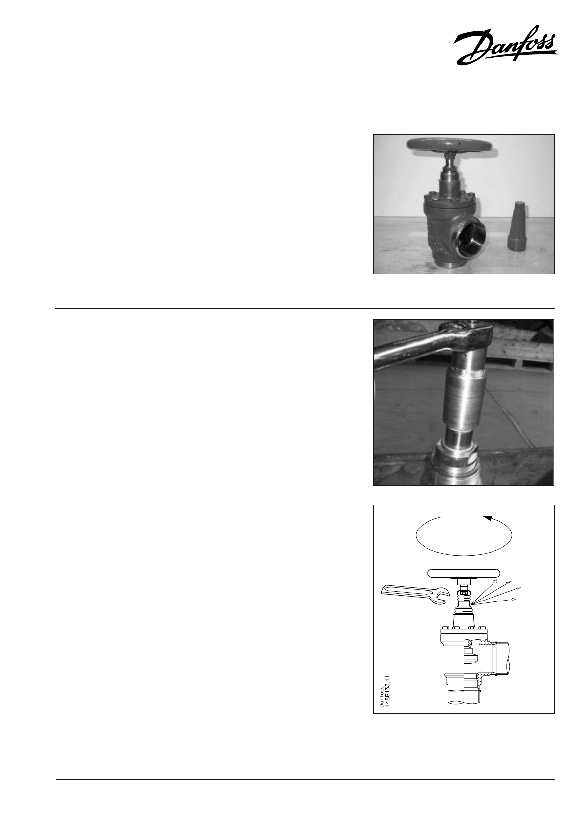
Back-seating To back-seat the valve, turn the spindle counter-
qualied to work on refrigeration systems and
be completely familiar with the system they are
about to service.
Any person intending to service a valve should
carefully read this Standard Operational
Procedure and the description of the particular
valve and its operation before any work begins.
If there are any questions, contact Danfoss before
proceeding with the work.
removed if there is internal pressure in the valve.
However, if the following precautionary measures
are taken, the packing gland can be removed
with the valve still under pressure, provided that
the valve is safely back-seated.
clockwise until the valve is fully open.
Use a 25 mm wrench.
Tighten the spindle counter-clockwise with
50 Nm ± 5 Nm (36.88 ft-lb ± 3.69 ft-lb) of force.
148R 9 628
Pressure equalization Important!
© Danfoss A/S (MWA), 2016-04 DKRCI.PI.KD2.Q2.02 / 520H9650 1
A small amount of refrigerant may still have
accumulated behind the packing gland; it is
extremely important that the service personnel
are using appropriate protection equipment
suitable for the actual refrigerant.
In some cases, pressure forms behind the packing
gland. Therefore, it is important to mount a
handwheel (or a similar device). It should be
fastened on top of the spindle while the pressure
is equalized in order to ensure that the packing
gland can be safely removed. The pressure can be
equalized by slowly unscrewing the gland.
Do not remove the packing gland if the valve is
not completely back-seated (not sealed tight –
see specications above). If it is not possible to
properly back-seat the valve (meaning potentially
trapped refrigerant pressure behind the packing
gland is not completely relieved within a few
seconds when the packing gland is unscrewed),
retighten the packing gland. Contact Danfoss
(it may be necessary to pump out (evacuate)
the system before proceeding with the removal
of the packing gland). If pump-out is required,
it is very important to ensure that the internal
pressure is reduced to atmospheric pressure or
below before the packing gland is unscrewed.

Packing gland replacement – SVA-S/L, SVA-ST/LT, SVA-HS – size DN 200
Inspect the internal surface If two grooves can be seen on the surface, go to
Step 1 Measure the distance from the top side of the
step 1.
If no groove is seen on the surface, go to step 2.
bushing to the top side of the bonnet.
The dimension should be between 50 mm and
52 mm (1.97 in. to 2.05 in.).
Be sure not to put the top side of the calipers into
the groove of the bushing, use a ashlight for
assistance.
If the measurement is within the specied range,
please proceed to step 3.
If this measurement is not within the specied
range of 50 mm – 52 mm (1.97 in. – 2.05
in.), reinstall the existing packing gland into
the bonnet and contact your local Danfoss
Representative for further details.
Step 2 Use the tools provided (number 9 in repair kit
148B6473) to remove the washer.
Be sure not to scratch the spindle while removing
the washer with the wire tools.
2 DKRCI.PI.KD2.Q2.02 / 520H9650 © Danfoss A/S (MWA), 2016-04

Packing gland replacement – SVA-S/L, SVA-ST/LT, SVA-HS – size DN 200
Step 3 To install the new packing gland, apply some
Molycote G4500 grease completely around the
O-rings of the packing gland (see picture 1).
Place the protection cap (number 10 in repair
kit 148B6473) on the top of the spindle. This
will protect the packing gland from the spindle
thread (see picture 2).
Place the packing gland on the spindle with
caution in order not to damage the internal seals
of the packing gland (see picture 3).
If you have a valve with seal cap, the seal cap can
be utilized to assist in pushing the packing gland
down into the bonnet assembly until the packing
gland makes positive engagement between the
packing gland and spindle threads (see picture
4). If you do not have a seal cap, a rubber mallet
can replace the cap for this operation.
Step 4 Complete the installation of the packing gland
into the bonnet by using a 46 mm wrench.
Tighten to a torque value of 80 Nm ± 10 Nm
(59.01 ft-lb ± 7.38 ft-lb).
Step 5 Carefully move the valve o of its backseat
position by turning the spindle ¼ to ½ of a turn.
Conduct a leak check via standard methods such
as soap bubbles or refrigerant detection device
to make sure that the packing gland has been
installed properly and no leaks have occurred.
If leaks were detected; repeat the process from
the beginning (page 1, Back-seating).
If no leaks were detected, the valve can be
returned to operation, and the valve cone placed
in either fully open or fully closed position.
© Danfoss A/S (MWA), 2016-04 DKRCI.PI.KD2.Q2.02 / 520H9650 3

Packing gland replacement – SVA-S/L, SVA-ST/LT, SVA-HS – size DN 200
4 DKRCI.PI.KD2.Q2.02 / 520H9650 © Danfoss A/S (MWA), 2016-04
 Loading...