

Page 1
Data Sheet
Float valve
Type SV 4, SV 5 and SV 6
Liquid level regulators in refrigeration, freezing
and air conditioning systems
SV 4, SV 5 and SV 6 are for use on the low
pressure side as modulating liquid level
regulators in refrigeration, freezing and air
conditioning systems with ammonia and other
common types of refrigerants.
Features:
• Reliable function
• Stable regulation, even during momentary
load change
• Liquid injection into the oat housing or
directly into the evaporator through external
pipe connection
• Orice assembly and lter can be replaced
without evacuating the oat housing
• Can be supplied without oat housing for
direct installation in the system (special order
only)
• Can be used as pilot oat for PMLF if
mounted with special orice (diameter Ø2.5
mm)
• Classication: DNV, CRN, BV, EAC etc. To get
an updated list of certication on the
products please contact your local Danfoss
Sales Company.
AI175286419654en-000601
Page 2
Direct liquid injection into the oat housing 4 pcs. M6
screws (pos. 23) are removed, and pos. 24 remains
blanked o. This leaves four holes through which liquid
expands directly.
4 pcs. M6 screws (pos. 23) are removed, and pos. 24 remains
blanked o. This leaves four holes through which liquid
expands directly.
Used in large evaporators with long pipe lines.
pos. 24 is removed and weld connection is mounted
pos. 23 remains screwed
Float valve, Type SV 4, SV 5 and SV 6
Applications
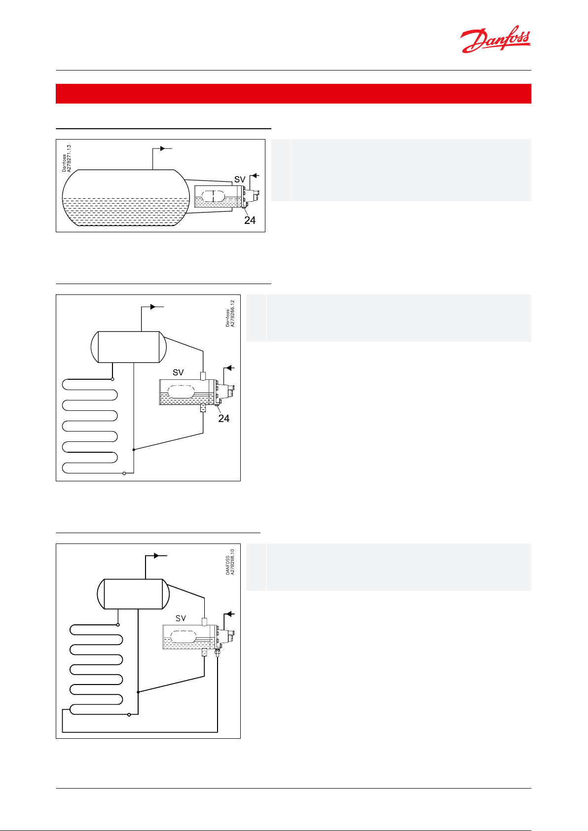
The liquid expands into the oat housing
NOTE:
If the capacity is too high, only remove two or three screws. Pos. 23 and 24, see .Table 7
The liquid expands into the oat housing
NOTE:
If the capacity is too high, only remove two or three screws. Pos. 23 and 24, see Table 7
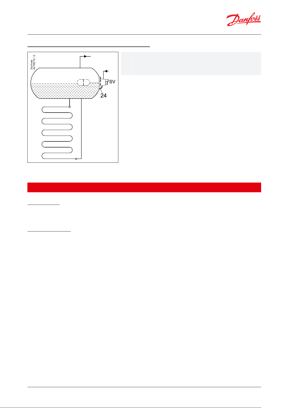
The liquid expands into the evaporator
NOTE:
Pos. 23 and 24, see Table 7
© Danfoss | Climate Solutions | 2021.02 AI175286419654en-000601 | 2
Page 3
4 pcs. M6 screws (pos. 23) are removed, and pos. 24 remains
blanked o. This leaves four holes through which liquid
expands directly.
Float valve, Type SV 4, SV 5 and SV 6
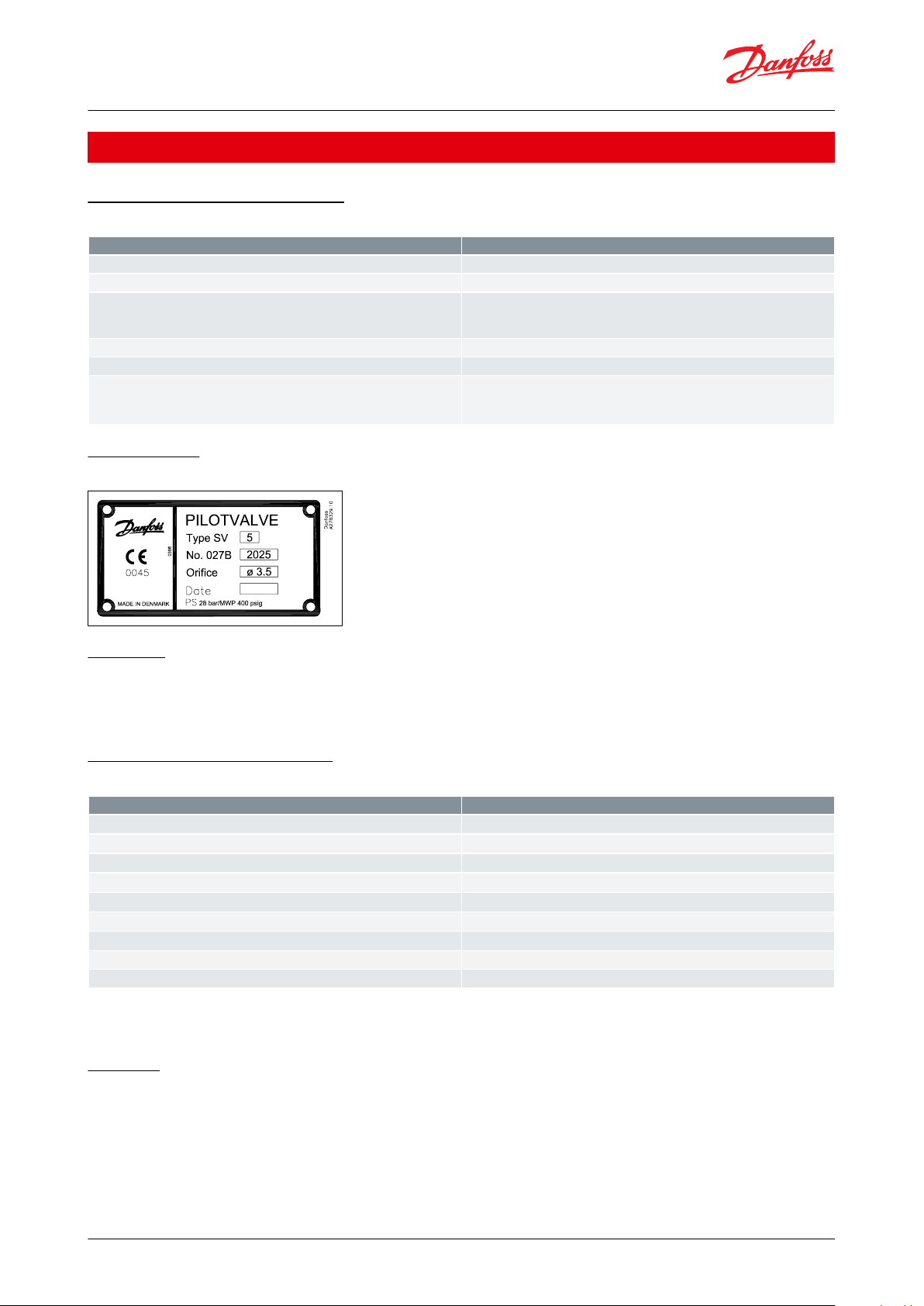
The liquid expands directly into the surge drum
NOTE:
If the capacity is too high, only remove two or three screws. Pos. 23 and 24, see Table 7
Media
Refrigerants
Applicable to HCFC, HFC and R717 (Ammonia). Use with ammable hydrocarbons cannot be recommended; please
contact Danfoss.
New refrigerants
Danfoss products are continually evaluated for use with new refrigerants depending on market requirements.
When a refrigerant is approved for use by Danfoss, it is added to the relevant portfolio, and the R number of the
refrigerant (e.g. R513A) will be added to the technical data of the code number. Therefore, products for specic
refrigerants are best checked at store.danfoss.com/en/, or by contacting your local Danfoss representative.
© Danfoss | Climate Solutions | 2021.02 AI175286419654en-000601 | 3
Page 4
Description
Values
P band
Approx. 35 mm
Max. working pressure
MWP = 28 bar
Max. Δp
SV 4 = 23 bar
SV 5 = 21 bar
SV 6 = 19 bar
Media temperature
-50 °C to 120 °C
Max. test pressure
MTP = 32 bar
kv value and diameter for orice
SV 4: kv = 0.23 m3/h D = 3.0 mm
SV 5: kv = 0.31 m3/h D = 3.5 mm
SV 6: kv = 0.43 m3/h D = 4.0 mm
Description
Values
Refrigerant
R717 (NH
3
)
Evaporating capacity
Q
e
= 145 kW
Evaporating temperature
t
e
= -10 °C (~ pe = 2.9 bar abs.)
Condensing temperature
t
c
= +30 °C (~ pc = 11.7 bar abs.)
Liquid temperature ahead of SV
t
l
= +20 °C
Subcooling
Δtsub = t
c
− tl = 30 °C − 20 °C = 10 K
Pressure drop in SV
Δp = p
c
− pe = 11.7 − 2.9 = 8.8 bar
Correction factor k for 10 K subcooling
= 0.98
Corrected capacity
145 × 0.98 = 142 kW
Float valve, Type SV 4, SV 5 and SV 6
Product specication
Pressure and temperature data
Table 1: Pressure and temperature data
Identication
Figure 1: Identication
Materials
• Gaskets are non asbestos
• Valve housing made of lowtemperature cast iron, spherical (EN-GJS-400-18-LT)
• Float housing: ST 35.8 DIN 17175 W. no. 1.0305
Dimensioning example for SV
Table 2:
NOTE:
At te = -10 °C and Δp = 8 bar SV 5 yields 147 kW and can therefore be used.
Capacity
The values in the capacity tables are based on a subcooling of 4 K just ahead of the SV valve. If the subcooling is
more or less than 4 K, refer to the following correction factors.
© Danfoss | Climate Solutions | 2021.02 AI175286419654en-000601 | 4
Page 5
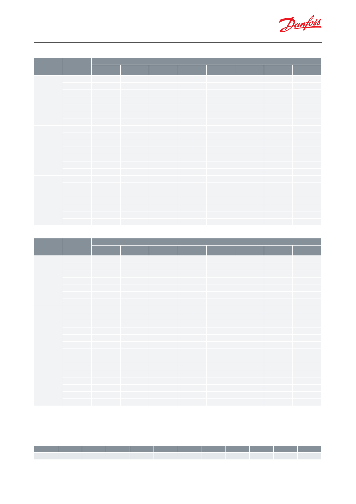
Type
Evaporating
temperature
te [°C]
Capacity in kW at pressure drop across valve ∆p bar
0.8
1.2
1.624812
16
SV 4
103745525879105
122
13403947545981
107
124
136
-104048556182108
125
137
-204149566283109
125
137
-304250576384109
125
136
-404251586384108
124
135
-504351586383107
122
133
SV 5
1051627178
107
143
166
183053647381110
145
168
185
-1054667583
112
147
170
1862056677684113
148
170
186
-3057687885
114
148
170
185
-4058697886
114
147
168
184
-5058697886
113
146
167
182
SV 6
10688395105
144
191
222
2450718698
108
147
195
226
248
-107388
101
111
150
197
227
250
-207590
103
113
152
198
228
250
-307692
104
115
153
198
227
248
-407793
105
115
153
197
226
246
-507893
105
115
152
196
223
243
Type
Evaporating
temperature
te [°C]
Capacity in kW at pressure drop across valve ∆p bar
0.8
1.2
1.624812
16
SV 4
10
8.5
10.3
11.7
12.9
17.2
21.8
24.1
25.108.9
10.7
12.2
13.5
17.8
22.4
24.6
25.7
-10
9.3
11.2
12.71418.3
22.82525.9
-20
9.7
11.6
13.1
14.4
18.7
23.1
25.1
25.9
-30
9.9
11.8
13.4
14.6
18.9
23.12525.7
-40
10.1
12.1
13.6
14.8
18.9
22.9
24.7
25.3
-50
10.3
12.1
13.6
14.8
18.8
22.6
24.2
24.8
SV 5
10
11.61415.9
17.6
23.4
29.6
32.7
34.2012.1
14.6
16.7
18.4
24.3
30.5
33.5
34.9
-10
12.7
15.2
17.31924.9
31.13435.3
-20
13.1
15.7
17.8
19.6
25.4
31.4
34.1
35.3
-30
13.5
16.1
18.2
19.9
25.7
31.43435
-40
13.8
16.4
18.4
20.1
25.7
31.2
33.6
34.5
-501416.5
18.5
20.2
25.6
30.73333.7
SV 6
10
15.5
18.7
21.3
23.6
31.4
39.7
43.9
45.8016.3
19.6
22.3
24.6
32.6
40.94546.8
-101720.4
23.2
25.5
33.5
41.7
45.6
47.3
-20
17.6
21.1
23.9
26.2
34.1
42.1
45.8
47.3
-30
18.1
21.6
24.4
26.7
34.5
42.1
45.647-40
18.52224.72734.5
41.84546.2
-50
18.7
22.2
24.82734.3
41.2
44.2
45.2
∆t K241015202530354045
50
k
1.0110.98
0.96
0.94
0.92
0.91
0.89
0.87
0.86
0.85
Float valve, Type SV 4, SV 5 and SV 6
Table 3: R717 (NH3)
Table 4: R22
Correction factors
When dimensioning, multiply the evaporating capacity by the correction factor k, dependent on the subcooling
Δtsub just ahead of the valve. The corrected capacity can then be found in the capacity table.
Table 5: R717 (NH3)
© Danfoss | Climate Solutions | 2021.02 AI175286419654en-000601 | 5
Page 6
∆t K241015202530354045
50
k
1.0110.96
0.93
0.9
0.87
0.85
0.83
0.8
0.78
0.77
No.
Part
Material
DIN / EN
1
Bottom ange for oat valve
Steel
P275NL1
EN10028-3
2
Tube for valve body
Steel
TTST35N
DIN17173
3
Connection for oat house
Steel
TTST35N
DIN17173
4
Top cover for oat valve
Steel
P275NL1
EN10028-3
5
Valve housing
Low temperature, cast iron
(spherical)
EN-GJS-400-18LT
EN1563
6
Spindle
Stainless steel
7
Spring
Steel
8
Sealing ring
Nylon (PA 6)
9
O-ring
Cloroprene (Neoprene)
10
Distance ring
Nylon (PA 6)
11
Packing ring
Nylon (PA 6)
12
Packing box
Steel13Cap
Steel14Float
Stainless steel
15
Adjusting ring
Steel
Float valve, Type SV 4, SV 5 and SV 6
Table 6: R22
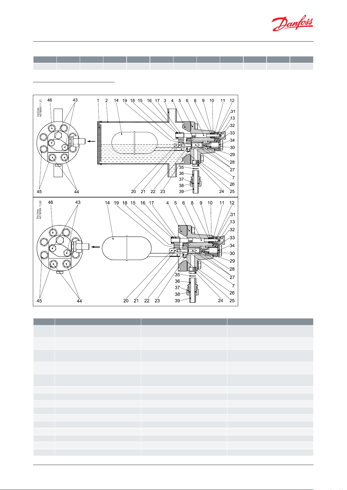
Construction and function
Figure 2: Construction and function
Table 7: Construction and function
© Danfoss | Climate Solutions | 2021.02 AI175286419654en-000601 | 6
Page 7
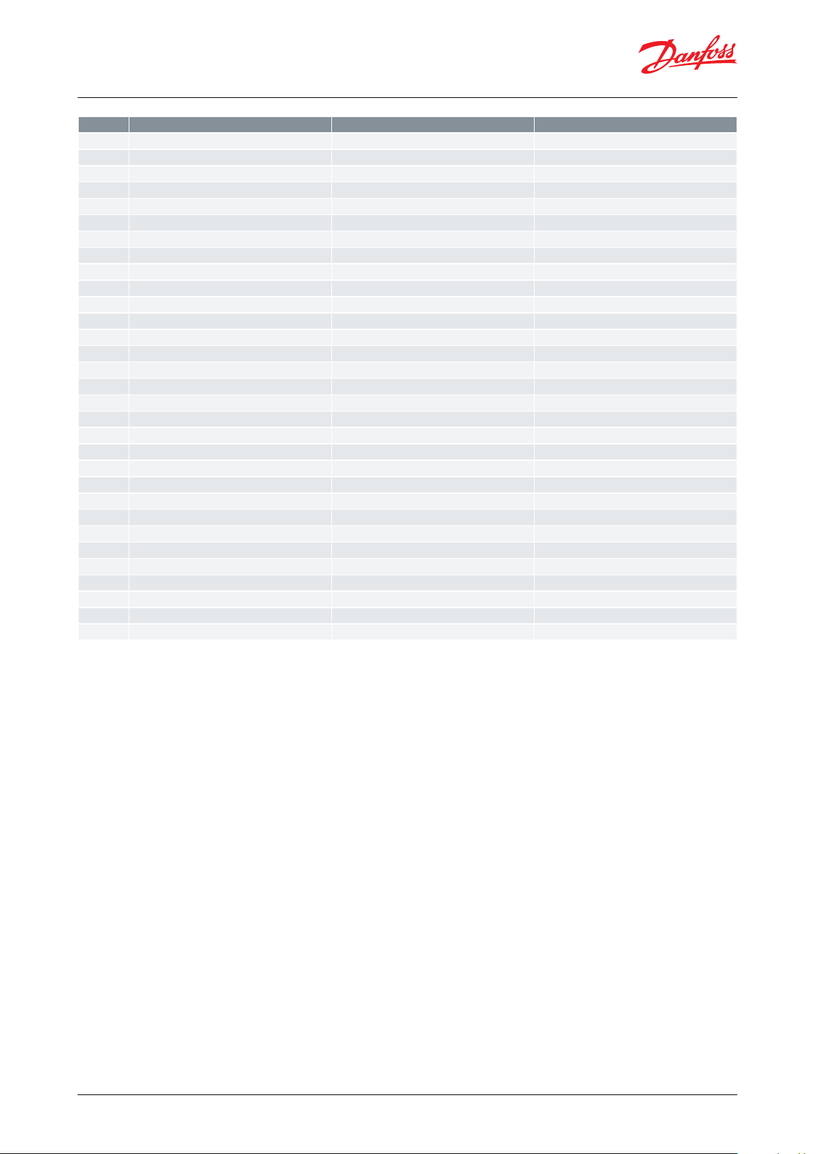
No.
Part
Material
DIN / EN
16
Pin
Steel
17
Fork for spindle
Steel18Screw
Steel
19
Locking ring
Steel20Pin
Steel21Pin
Steel
22
Cover with guide
Steel23Screw
Steel24Plug
Steel25Gasket
Non asbestos
26
Gasket
Aluminium
27
Valve cone (guide) with pin
Steel / Nylon (PA6)
28
Valve cone
Teon (PTFE)
29
O-ring
Cloroprene (Neoprene)
30
Nozzle
Teon (PTFE)
31
Gasket
Non asbestos
32
Filter
Steel / Stainless steel
33
Spring
Steel
34
Cover for lter
Steel35Gasket
Aluminium
36
Nipple
Steel
37
Union nut
Steel38Gasket
Aluminium
39
Welding nipple
Steel
40
Locking ring
Steel41Ring
Nylon (PA6)
42
Pin
Steel43Screw
Stainless steel
A2-7044Screw
Stainless steel
A2-7045Washer
Steel46Screw
Stainless steel
A2-70
Float valve, Type SV 4, SV 5 and SV 6
SV 4-6 oat valves are for low pressure operation only. They are used for ooded evaporators, where only slight
variations in the liquid level can be accepted. When the liquid level decreases, the oat moves downwards. This
opens the orice (pos. 7) and the amount of liquid injected is increased.
The liquid inlet line should be dimensioned in such a way that acceptable liquid velocities and pressure drops are
obtained. This is particularly important when the liquid is only slightly subcooled, since valve capacity is reduced
considerably if ashgas occurs in the liquid ahead of the orice.
The ashgas quantity which occurs on expansion is removed through the balance pipe. On refrigeration plant using
uorinated refrigerants, slight subcooling and a large pressure drop can result in a ashgas quantity of approx. 50%
of the injected liquid quantity.
Therefore the pressure drop in this balance pipe must be kept at a minimum, otherwise there is a risk that:
• the liquid level in the evaporator will vary to an unacceptable degree as a function of evaporator load
• the absolute dierence between the liquid level of the evaporator and the SV valve
If too large amounts of ash gas are created it is recommended to use the external injection connection or let the
liquid expand directly into the surge drum. See application drawings 3 and 4.
See instruction for SV 4-6 for:
• Cleaning of strainer
• Change of orice
• Change of valve plate
© Danfoss | Climate Solutions | 2021.02 AI175286419654en-000601 | 7
Page 8

Float valve, Type SV 4, SV 5 and SV 6
Dimensions and weight
NOTE:
Weight: 19.6 kg
NOTE:
Weight: 9.7 kg
NOTE:
Weight: 3.1 kg
© Danfoss | Climate Solutions | 2021.02 AI175286419654en-000601 | 8
Page 9
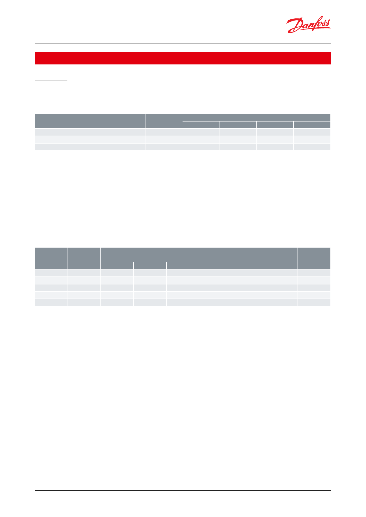
Valve type
Orice diameter
Code no.
Code no. without
housing
(1)
Rated capacity in kW
(2)
R717
R22
R134a
R404A
SV 4
∅ 3.0 mm
027B2024
027B2014
1022116.4
15.4
SV 5
∅ 3.5 mm
027B2025
027B2015
138
28.6
22.3
21
SV 6
∅ 4.0 mm
027B2026
027B2016
186
38.3
29.9
28.1
Orice
diameter
k
v
Capacities at -10°C evaporating temperature at pressure drop across valve ∆P bar
Code no.
(1)
R717
R22
471047
10
∅
1.0 mm
0.026912
13.5
1.6
2.2
2.4
027B2080
∅
1.5 mm
0.062127293.8
4.9
5.2
027B2081
∅
2.0 mm
0.13546506.3
8.3
9
027B2082
∅
2.5 mm
0.16567081101315
027B2083
∅
2.8 mm
0.27087.5
1011216
18
027B2084
Float valve, Type SV 4, SV 5 and SV 6
Ordering
Regulator
The code nos. stated apply to oat valves types SV 4, 5 and 6 with two 1" weld connections for balance tubes and
two ½" weld joints for liquid and evaporator connections respectively.
Table 8: Ordering
(1)
(1)
Flange for mounting without housing Code no. 027B2027
Flange for mounting without housing Code no. 027B2027
(2)
(2)
The rated capacity refers to the valve capacity at evaporating temperature tc = +5 °C, condensing temp. tc = +32 °C and liquid temperature tl =
The rated capacity refers to the valve capacity at evaporating temperature tc = +5 °C, condensing temp. tc = +32 °C and liquid temperature tl =
+28 °C
+28 °C
Spare parts and accessories
Smaller orices for the SV 4 - 6 are available as spare parts and can be mounted in the SV 4 - 6 if smaller capacities
are required.
• Seal kit: 027B2070
• Other spare parts: See spare parts catalogue
Table 9: Special orice code no. and rated capacities for SV 4 - 6
(1)
(1)
The code no. includes
The code no. includes
orice and all necessary gaskets
orice and all necessary gaskets
NOTE:
The SV 4 - 6 mounted with special orice diameter ∅2.5 mm is recommended as pilot oat valve for the servooperated level regulators type PMFL for higher capacities.
© Danfoss | Climate Solutions | 2021.02 AI175286419654en-000601 | 9
Page 10

Type
File name
Document type
Document topic
Approval authority
SV 4
19.10327.266
Marine - Safety Certicate
RMRS
SV 5
SV 6
SV 4, SV 5 and SV 6
Classied for
Fluid group I
Category
II
SV 4, SV 5 and SV 6 are approved in accordance with the European standard specied in the Pressure Equipment Directive
and are CE marked. For further details / restrictions - see Installation guide.
Float valve, Type SV 4, SV 5 and SV 6
Certicates, declarations, and approvals
The list contains all certicates, declarations, and approvals for this product type. Individual code number may have
some or all of these approvals, and certain local approvals may not appear on the list.
Some approvals may change over time. You can check the most current status at danfoss.com or contact your local
Danfoss representative if you have any questions.
Table 10: Valid approvals
Table 11: Compliance
Table 12: Pressure Equipment Directive (PED)
© Danfoss | Climate Solutions | 2021.02 AI175286419654en-000601 | 10
Page 11
Online support
Danfoss oers a wide range of support along with our products, including digital product information, software,
mobile apps, and expert guidance. See the possibilities below.
The Danfoss Product Store
The Danfoss Product Store is your one-stop shop for everything product related—no matter where
you are in the world or what area of the cooling industry you work in. Get quick access to essential
information like product specs, code numbers, technical documentation, certications, accessories,
and more.
Start browsing at store.danfoss.com.
Find technical documentation
Find the technical documentation you need to get your project up and running. Get direct access to
our ocial collection of data sheets, certicates and declarations, manuals and guides, 3D models
and drawings, case stories, brochures, and much more.
Start searching now at www.danfoss.com/en/service-and-support/documentation.
Danfoss Learning
Danfoss Learning is a free online learning platform. It features courses and materials specically
designed to help engineers, installers, service technicians, and wholesalers better understand the
products, applications, industry topics, and trends that will help you do your job better.
Create your Danfoss Learning account for free at www.danfoss.com/en/service-and-support/learning.
Get local information and support
Local Danfoss websites are the main sources for help and information about our company and
products. Find product availability, get the latest regional news, or connect with a nearby expert—all
in your own language.
Find your local Danfoss website here: www.danfoss.com/en/choose-region.
Spare Parts
Get access to the Danfoss spare parts and service kit catalog right from your smartphone. The app
contains a wide range of components for air conditioning and refrigeration applications, such as
valves, strainers, pressure switches, and sensors.
Download the Spare Parts app for free at www.danfoss.com/en/service-and-support/downloads.
Coolselector®2 - nd the best components for you HVAC/R system
Coolselector®2 makes it easy for engineers, consultants, and designers to nd and order the best
components for refrigeration and air conditioning systems. Run calculations based on your operating
conditions and then choose the best setup for your system design.
Download Coolselector®2 for free at coolselector.danfoss.com.
Danfoss can accept no responsibility for possible errors in catalogues, brochures and other printed material. Danfoss reserves the right to alter its
products without notice. This also applies to products already on order provided that such alterations can be made without subsequential
changes being necessary in specications already agreed. All trademarks in this material are property of the respective companies. Danfoss and
the Danfoss logotype are trademarks of Danfoss A/S. All rights reserved.
© Danfoss | Climate Solutions | 2021.02 AI175286419654en-000601 | 11
 Loading...