

Page 1
Data Sheet
Float valve
Type SV 1 and SV 3
For industrial refrigeration liquid level regulation
Several oat valves are available for Industrial
refrigeration liquid level control in the product
group “Liquid level regulating valves”, such as
HFI and SV series. The SV series contains the
following types: SV 1, SV 3, SV 4, SV 5 and SV 6,
some of which can be delivered as dedicated
“E” versions for hydrocarbon application.
The SV 1 and SV 3 can be used separately as a
modulating liquid level regulator in
refrigerating, freezing and air conditioning
systems for ammonia or uorinated
refrigerants.However, in most cases, the SV is
used as a oat pilot valve for the main
expansion valve type PMFH.
The SV 1 and SV 3 are used as liquid level
regulators in either low pressure applications or
in high pressure applications. Adaptation to the
specic application is done by the orientation
of the valve and thereby the oat functions
AI221686430747en-001001
Page 2
Description
Values
Refrigerants
R134a, R22, R401A, R402A, R404A, R407A, R407B, R407C, R407F, R409A, R410A,
R421A, R502, R507, R717
Application
High Pressure Liquid Level Control System (HP LLRS)
Low Pressure Liquid Level Control System (LP LLRS)
Design versions
Media temperature range
-50 °C – 65 °C
P-band [mm]
35 mm
MWP [bar]
28 bar
K
v
value [m3/h]
0.06 for SV 1
0.14 for SV 3
Rated capacity (kW)
SV1: 25
SV3: 64
(R717 +5/32 °C, Tl = 28 °C)
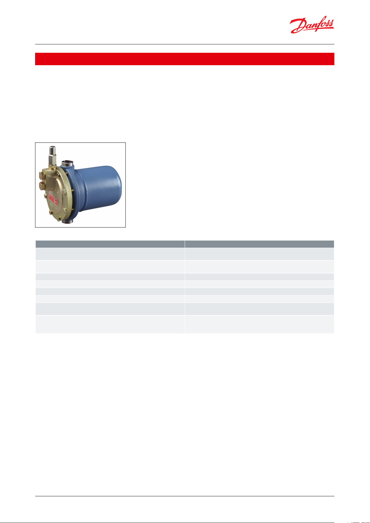
Float valve, Type SV 1 and SV 3
Portfolio overview
The SV 1 and SV 3 can be used separately as a modulating liquid level regulator in refrigerating, freezing and air
conditioning systems for ammonia or uorinated refrigerants.
However, in most cases, the SV is used as a oat pilot valve for the main expansion valve type PMFH.
Several oat valves are available for Industrial refrigeration liquid level control in the product group “Liquid level
regulating valves”, such as HFI and SV series. The SV series contains the following types: SV 1, SV 3, SV 4, SV 5 and SV
6, some of which can be delivered as dedicated “E” versions for hydrocarbon application.
Figure 1: Float valve SV 1 and SV 3
Table 1: Portfolio overview
© Danfoss | Climate Solutions | 2021.02 AI221686430747en-001001 | 2
Page 3
Float valve, Type SV 1 and SV 3
Applications
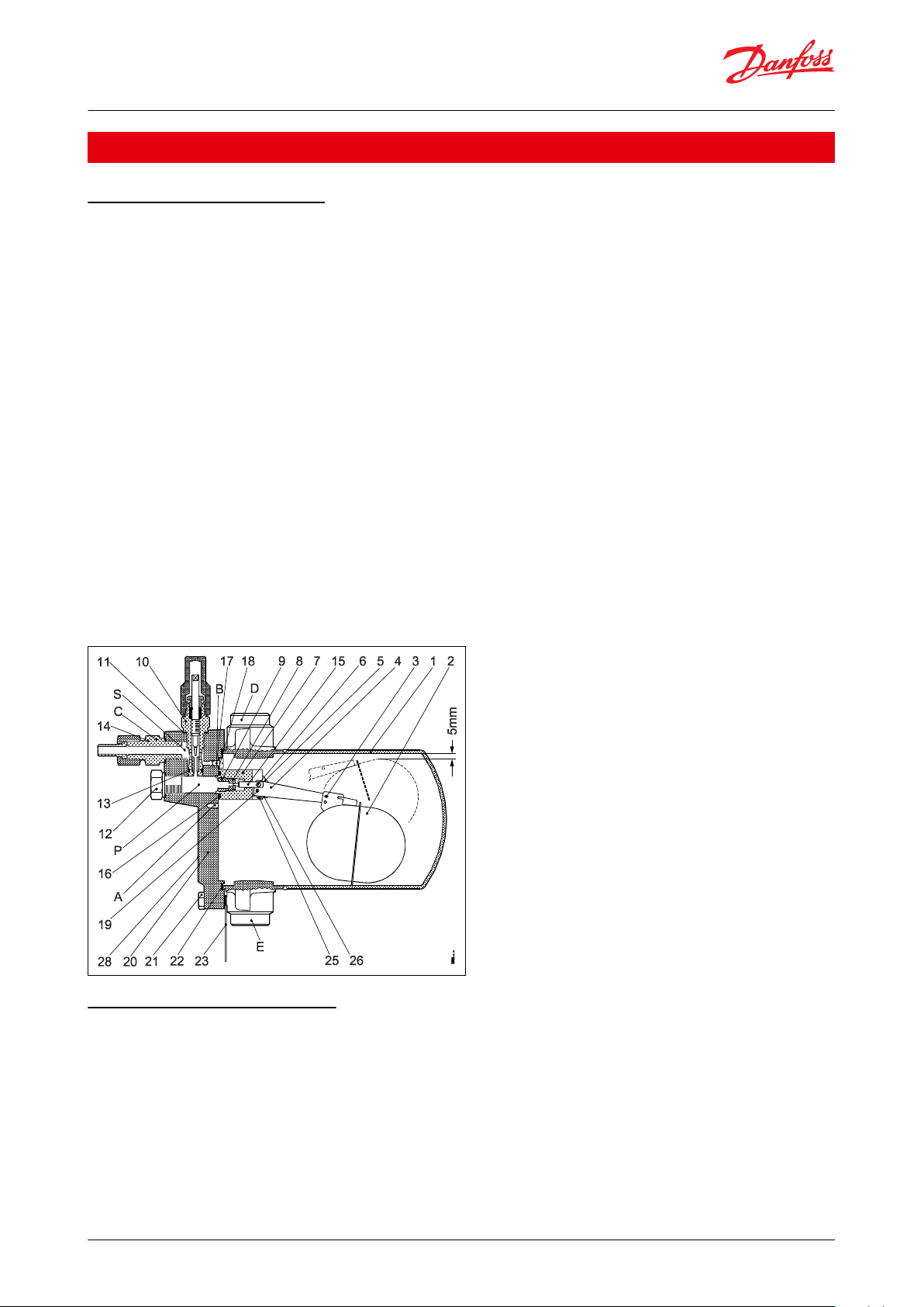
SV (L), low-pressure function
SV (L), low-pressure function
SV (L) is used for small, ooded evaporators, where only slight variations in the liquid level can be accepted.
When the liquid level falls, the oat pos. (2) moves downwards. This draws the needle pos. (15) away from the orice
and the amount of liquid injected is increased.
The liquid inlet line, which is mounted on the nipple pos. (C), should be dimensioned in such a way that acceptable
liquid velocities and pressure drops are obtained.
This is particularly important when the liquid is only slightly subcooled, since valve capacity is reduced considerably
if ashgas occurs in the liquid ahead of the orice and wear is strongly increased.
See the suggested dimensions for the liquid line in "Pipe dimensions". Refer section Dimensions and weights
The ashgas quantity which occurs on expansion is removed through the balance pipe from pos. (D). On
refrigeration plant using uorinated refrigerants, slight subcooling and a large pressure drop can give a ashgas
quantity of approx. 50% of the injected liquid quantity. Therefore the pressure drop in this balance pipe must be
kept at a minimum, since there will otherwise be a risk that the liquid level in the evaporator will vary to an
unacceptable degree as a function of evaporator load the absolute dierence between the liquid level of the
evaporator and the SV valve will be too large.
See the suggested dimensions for the balance pipe in "Pipe dimensions". Refer section Dimensions and weights
Figure 2: SV (L), low-pressure function
SV (H), high-pressure function
SV (H), high-pressure function
When the liquid level rises, the oat pos. (2) moves upwards. This draws the needle pos. (15) away from the orice
and the excess liquid is drawn away.
On refrigeration plant using uorinated refrigerants slight subcooling and a large pressure drop can, as already
mentioned, cause the formation of a large amount of ashgas.
This mixture of liquid and vapour has to pass through the nipple pos. (C) and out into the liquidline.
If the dimensions of the line are too small, a pressure drop will occur which can reduce the capacity of the SV (H)
valve considerably. This will mean a risk of inadvertent liquid accumulation in the condenser or receiver.
© Danfoss | Climate Solutions | 2021.02 AI221686430747en-001001 | 3
Page 4
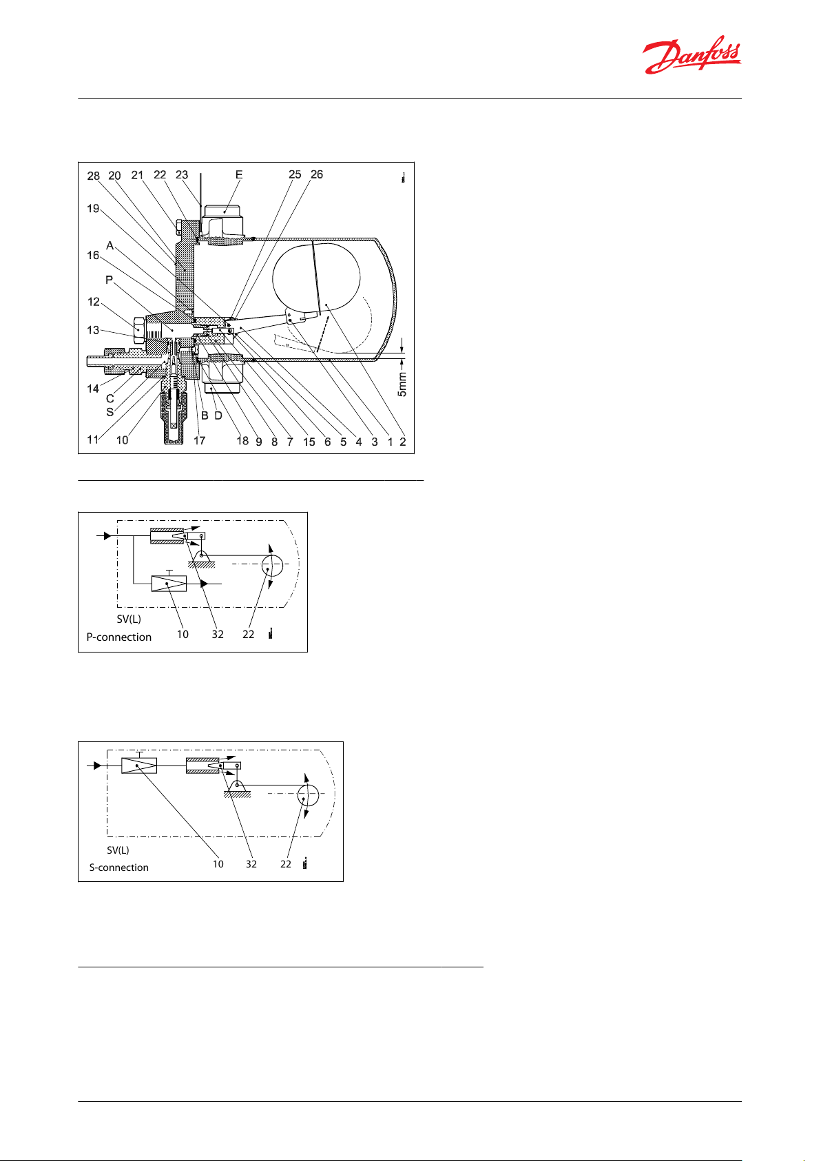
SV(L)
10 32 22
P-connection
SV(L)
10 32 22
S-connection
Float valve, Type SV 1 and SV 3
See the suggested dimensions for the liquid line in "Pipe dimensions". Refer section Dimensions and weights
Figure 3: SV (H), high-pressure function
The connection nipple (C) can be mounted either in P or in S
Figure 4: P-connection (= parallel)
NOTE:
With P-connection an SV with closed oat orice will have a capacity which corresponds to the degree of opening of
the adjustable throttle valve 10.
Figure 5: S-connection (= series)
NOTE:
With S-connection the throttle valve 10 will function as a pre-orice on SV (L) and as a post orice on SV (H)
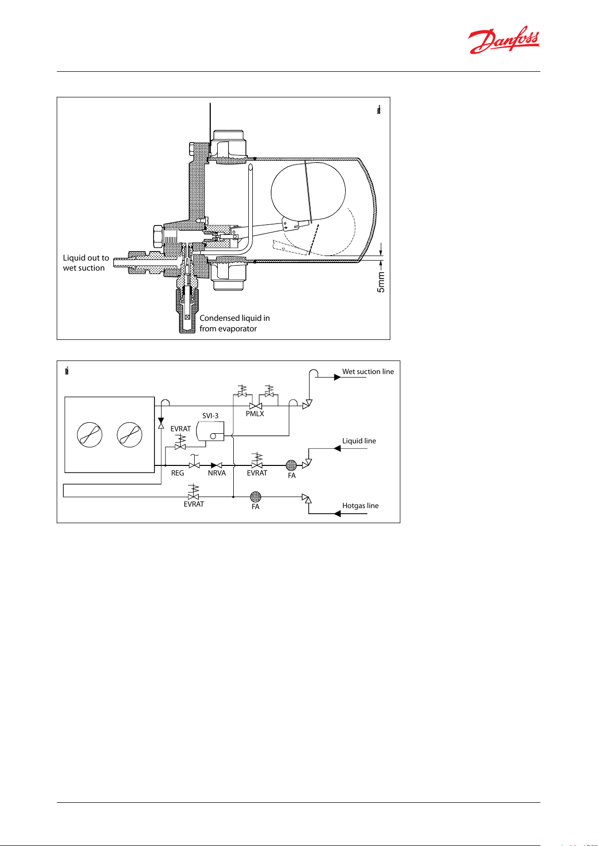
SV 1 - 3 used as a high pressure defrost drain oat valve
SV 1 - SV 3 can be used as a defrost drain oat valve, when one balance pipe is sealed o and the liquid level
regulator
is mounted with a special kit (code no. 027B2054) consisting of:
• Special orice and orice needle with a larger kv-value of 0.28 m3/h.
• Gas drain pipe
© Danfoss | Climate Solutions | 2021.02 AI221686430747en-001001 | 4
Page 5
Liquid out to
wet suction
Condensed liquid in
from evaporator
Wet suction line
Liquid line
PMLX
SVI-3
EVRAT
EVRAT
REG
NRVA
Hotgas line
EVRAT
FA
FA
Float valve, Type SV 1 and SV 3
Figure 6: SV 1 - 3 tted with the special kit (code no. 027B2054)
Figure 7: Application example
NOTE:
SV 1 - 3 with special kit mounted as defrost drain foat valve on a fooded evaporator with hotgas defrost.
© Danfoss | Climate Solutions | 2021.02 AI221686430747en-001001 | 5
Page 6

Float valve, Type SV 1 and SV 3
Media
Refrigerants
The SV 1 and SV 3 can be used separately as a modulating liquid level regulator in refrigerating, freezing and air
conditioning systems for ammonia or uorinated refrigerants.
SV oat valves are currently authorized by Danfoss for use with several R numbers HCFC, non-ammable HFC,
Ammonia, CO2 and hydrocarbons. New refrigerants are added frequently to the list of Danfoss approved refrigerants
and added to the product types.
For an exhaustive and updated list, look up a code number in https://store.danfoss.com/en/.
New refrigerants
Danfoss products are continually evaluated for use with new refrigerants depending on market requirements.
When a refrigerant is approved for use by Danfoss, it is added to the relevant portfolio, and the R number of the
refrigerant (e.g. R513A) will be added to the technical data of the code number. Therefore, products for specic
refrigerants are best checked at store.danfoss.com/en/, or by contacting your local Danfoss representative.
© Danfoss | Climate Solutions | 2021.02 AI221686430747en-001001 | 6
Page 7

C
D
P
S
Nipple
Connection for balance pipe
Parallel connection of pos. C (screw 17 in pos.
A)
Series connection of pos. C (screw 17 in pos. B)
Description
Values
P band
35 mm
Temperature of medium
-50 °C – 65 °C
Max. working pressure
PS = 28 bar
Max. test pressure
p' = 36 bar
kv value for oat orice
SV 1 = 0.06 m3/h
SV 3 = 0.14 m3/h
No.
Part
Material
DIN / EN
1
Float housing
Stainless steel
Low temperature, steel
X5CrNi18-10, DIN 17440
P285QH, EN 10222-4
2
Float
Stainless steel
3
Split pin
Steel4Float arm
Stainless steel
5
Link
Steel6Pin
Stainless steel
7
Valve housing
Steel8O-ring
Cloroprene (Neoprene)
9
Float orice
Plastic10Manual regulation unit. Throttle valve
Steel11Gasket
Non asbestos
12
Plug
Steel13O-ring
Cloroprene (Neoprene)
14
Pilot connection (spare part)
Steel15Orice needle
Plastic
Float valve, Type SV 1 and SV 3
Product specication
Pressure and temperature data
Table 2: Pressure and temperature data
NOTE:
The highest kv value for the built-in throttle valve is 0.18 m3/h. The throttle valve can be used both in parallel and in
series with the oat orice.
Material specication
SV with low-pressure function
Figure 8: SV with low-pressure function
Table 3: SV with low-pressure function
© Danfoss | Climate Solutions | 2021.02 AI221686430747en-001001 | 7
Page 8

C
D
P
S
Nipple
Connection for balance pipe
Parallel connection of pos. C (screw 17 in pos.
A)
Series connection of pos. C (screw 17 in pos. B)
No.
Part
Material
DIN / EN
16
O-ring
Cloroprene (Neoprene)
17
Screw
Steel18Gasket
Non asbestos
19
Pin
Steel
20
Cover
Low temperature, cast iron
(spherical)
EN-GJS-400-18-LT
EN 1563
21
Screw
Stainless steel
A2-7022Gasket
Non asbestos
23
Label
Cardboard
25
Screw
Steel26Spring washer
Steel28Sign
Aluminium
No.
Part
Material
DIN / EN
1
Float housing
Stainless steel
Low temperature, steel
X5CrNi18-10, DIN 17440
P285QH, EN 10222-4
2
Float
Stainless steel
3
Split pin
Steel4Float arm
Stainless steel
5
Link
Steel6Pin
Stainless steel
7
Valve housing
Steel8O-ring
Cloroprene (Neoprene)
9
Float orice
Plastic10Manual regulation unit. Throttle valve
Steel11Gasket
Non asbestos
12
Plug
Steel13O-ring
Cloroprene (Neoprene)
14
Pilot connection (spare part)
Steel15Orice needle
Plastic16O-ring
Cloroprene (Neoprene)
17
Screw
Steel18Gasket
Non asbestos
19
Pin
Steel
20
Cover
Low temperature, cast iron
(spherical)
EN-GJS-400-18-LT
EN 1563
Float valve, Type SV 1 and SV 3
SV with high-pressure function
Figure 9: SV with high-pressure function
Table 4: SV with high-pressure function
© Danfoss | Climate Solutions | 2021.02 AI221686430747en-001001 | 8
Page 9

No.
Part
Material
DIN / EN
21
Screw
Stainless steel
A2-7022Gasket
Non asbestos
23
Label
cardboard
25
Screw
Steel26Spring washer
Steel28Sign
Aluminium
DANFOSS
27F691_01-2017
M16 × 1.5
AF 19
G 3/8 A
AF 22
∅ 6.5 / ∅ 10
Type
Evaporating tempera‐
ture te °C
Capacity in kW at pressure drop across valve ∆p bar
0.8
1.2
1.624812
16
SV 1
10
9.511131520273009.912141520273133-10
1012141521273133-20
1112141521273033-30
1112141520263033-40
1113141520262932-50
11121315202629
32
SV 3
10
2531353952717702632364052697883-10
2632364052687783-20
2631353952677682-30
2530343850667582-40
2429333649657380-50
23273135476471
79
Type
Evaporating tempera‐
ture te °C
Capacity in kW at pressure drop across valve ∆p bar
0.8
1.2
1.624812
16
SV 1
10
2.2
2.633.2
4.2
4.8
5.7
5.702.3
2.7
3.1
3.4
4.4
4.9
5.8
5.8
-10
2.4
2.8
3.2
3.5
4.555.8
5.9
-20
2.4
2.9
3.3
3.6
4.655.8
5.8
−30
2.5
2.9
3.3
3.6
4.555.7
5.7
-40
2.5
2.9
3.3
3.6
4.4
4.9
5.6
5.6
-50
2.6
2.9
3.3
3.5
4.3
4.8
5.4
5.4
Float valve, Type SV 1 and SV 3
Connections
Table 5: Pilot connection (weld / solder)
Capacity tables
The values in the capacity tables are based on a subcooling of 4 K just ahead of the SV valve.
If the subcooling is more or less than 4 K, refer to the correction factors provided after the capacity tables.
Table 6: R717 (ammonia)
Table 7: R22
© Danfoss | Climate Solutions | 2021.02 AI221686430747en-001001 | 9
Page 10

Type
Evaporating tempera‐
ture te °C
Capacity in kW at pressure drop across valve ∆p bar
0.8
1.2
1.624812
16
SV 3
10
5.6
6.8
7.7
8.51113151505.878
8.811131515
-10
6
7.3
8.2912131515-20
6.1
7.3
8.3
8.911131415
-30
6.2
7.3
8.1
8.811121414
-40
6.1
7.1
7.9
8.511121414
-50
5.9
6.9
7.6
8.211121314
∆t K
24101520253035404550k1.0110.98
0.96
0.94
0.92
0.91
0.89
0.87
0.86
0.85
∆t K
24101520253035404550k1.0110.96
0.93
0.9
0.87
0.85
0.83
0.8
0.78
0.77
74.5
106
132
170.5
92
92
5+2
122.6
155
141.5
ID 28
ID 28
ID 6.8
OD 9.8
Danfoss
27B326.12
Type
Weight
SV 1
5.7 kg
SV 3
5.7 kg
Float valve, Type SV 1 and SV 3
Correction factors
When dimensioning, multiply the evaporator capacity by a correction factor k dependent on the subcooling Δt
just ahead of the valve. The corrected capacity can then be found in the capacity table.
Table 8: R717 (ammonia)
Table 9: R22
sub
Dimensions and weights
Figure 10: SV1 and SV3
Table 10: SV 1 and SV 3 Dimensions and weights
Pipe dimensions
Liquid line
© Danfoss | Climate Solutions | 2021.02 AI221686430747en-001001 | 10
Page 11

Type
Dimensions
0.8 bar < ∆psv < 4 bar
4 bar < ∆psv < 16 bar
Steel tube
Steel tube
SV 1
3
⁄8 in.3⁄8 in.
SV 3
3
⁄8 in.1⁄2 in.
Type
Dimensions
0.8 bar < ∆psv < 4 bar
4 bar < ∆psv < 16 bar
Steel tube
Copper tube
Steel tube
Copper tube
SV 1
3
⁄8 in.3⁄8 in.3⁄8 in.1⁄2 in.
SV 3
3
⁄8 in.5⁄8 in.1⁄2 in.3⁄4 in.
Type
Dimensions
SV (L) 1
1 in.
SV (L) 3
1
1
⁄2 in.
Float valve, Type SV 1 and SV 3
The following suggested dimensions for the liquid line, which is connected to the nipple pos. C are based on a
maximum velocity in a line with subcooled ammonia of approx. 1 m/s and a maximuM velocity in a line with
subcooled uorinated refrigerant of approx. 0.5 m/s.
Table 11: R717 (ammonia)
Table 12: R22, R134a, R404A
Table 13: Upper balance pipe (connect to pos. D on SV (L)
© Danfoss | Climate Solutions | 2021.02 AI221686430747en-001001 | 11
Page 12
Valve type
Rated capacity in kW
Packing format
Qty./pack
Code no.
R717
R22
R134a
R404A
R12
R502
SV 1
25
4.7
3.9
3.7
3.1
3.4
Single pack
1 pc
027B2021
SV 3
641310
9.7
7.9
8.8
Single pack
1 pc
027B2023
Float valve, Type SV 1 and SV 3
Ordering
Table 14: SV 1 - SV 3 Ordering
NOTE:
The code nos. stated apply to oat valves, types SV 1 and SV 3 incl. ∅ 6.5 / ∅ 10 mm weld connection
line.
Balance tube connection (liquid/vapour): 1 in. weld / 1
1
⁄8 in. solder.
The rated capacity refers to the valve capacity at evaporating temperature te = +5 °C, condensing temp. tc = +32 °C
and liquid temperature tl = +28 °C.
(1)
for the pilot
1
3
⁄8 in. are connection can be supplied under code no. 027B2033.
© Danfoss | Climate Solutions | 2021.02 AI221686430747en-001001 | 12
Page 13

File name
Document type
Document topic
Approval authority
Д-DK.БЛ08.В.00191_18
EAC Declaration
Machinery & Equipment
EAC RU
0045 202 1204 Z 00354 19 D 001(00)
Pressure - Safety Certicate
TÜV
Д-DK.РА01.B.72054_20
EAC Declaration
PED
EAC RU
EU 033F0685.AK
EU Declaration
EMCD/PED
Danfoss
033F0691.AD
Manufacturers Declaration
RoHS
Danfoss
033F0473.AD
Manufacturers Declaration
ATEX
Danfoss
Д-DK.БЛ08.В.01592
EAC Declaration
EMC
EAC RU
Д-DK.МХ24.В.00273
EAC Declaration
Machinery & Equipment
EAC RU
Д-DK.БЛ08.B.01120_19
EAC Declaration
EMC
EAC RU
UL SA7200
Mechanical - Safety Certicate
UL
UA.1O146.D.00069-19
UA Declaration
PED
LLC CDC EURO-TYSK
UA.TR-089.1112.01-19
Pressure - Safety Certicate
PED
LLC CDC EURO-TYSK
Type
SV 1 and SV 3
Classied for
Fluid group I
Category
I
Pressure Equipment Directive (PED)
SV 1 and SV 3 are approved in accordance with the European standard specied in the Pressure Equipment Directive and are CE
marked.
For further details / restrictions - see Installation guide.
Float valve, Type SV 1 and SV 3
Certicates, declarations, and approvals
The list contains all certicates, declarations, and approvals for this product type. Individual code number may have
some or all of these approvals, and certain local approvals may not appear on the list.
Some approvals may change over time. You can check the most current status at danfoss.com or contact your local
Danfoss representative if you have any questions.
Table 15: Valid Approvals
Table 16: Compliance table
Table 17: Conformity Approvals
© Danfoss | Climate Solutions | 2021.02 AI221686430747en-001001 | 13
Page 14

Online support
Danfoss oers a wide range of support along with our products, including digital product information, software,
mobile apps, and expert guidance. See the possibilities below.
The Danfoss Product Store
The Danfoss Product Store is your one-stop shop for everything product related—no matter where
you are in the world or what area of the cooling industry you work in. Get quick access to essential
information like product specs, code numbers, technical documentation, certications, accessories,
and more.
Start browsing at store.danfoss.com.
Find technical documentation
Find the technical documentation you need to get your project up and running. Get direct access to
our ocial collection of data sheets, certicates and declarations, manuals and guides, 3D models
and drawings, case stories, brochures, and much more.
Start searching now at www.danfoss.com/en/service-and-support/documentation.
Danfoss Learning
Danfoss Learning is a free online learning platform. It features courses and materials specically
designed to help engineers, installers, service technicians, and wholesalers better understand the
products, applications, industry topics, and trends that will help you do your job better.
Create your Danfoss Learning account for free at www.danfoss.com/en/service-and-support/learning.
Get local information and support
Local Danfoss websites are the main sources for help and information about our company and
products. Find product availability, get the latest regional news, or connect with a nearby expert—all
in your own language.
Find your local Danfoss website here: www.danfoss.com/en/choose-region.
Spare Parts
Get access to the Danfoss spare parts and service kit catalog right from your smartphone. The app
contains a wide range of components for air conditioning and refrigeration applications, such as
valves, strainers, pressure switches, and sensors.
Download the Spare Parts app for free at www.danfoss.com/en/service-and-support/downloads.
Coolselector®2 - nd the best components for you HVAC/R system
Coolselector®2 makes it easy for engineers, consultants, and designers to nd and order the best
components for refrigeration and air conditioning systems. Run calculations based on your operating
conditions and then choose the best setup for your system design.
Download Coolselector®2 for free at coolselector.danfoss.com.
Danfoss can accept no responsibility for possible errors in catalogues, brochures and other printed material. Danfoss reserves the right to alter its
products without notice. This also applies to products already on order provided that such alterations can be made without subsequential
changes being necessary in specications already agreed. All trademarks in this material are property of the respective companies. Danfoss and
the Danfoss logotype are trademarks of Danfoss A/S. All rights reserved.
© Danfoss | Climate Solutions | 2021.02 AI221686430747en-001001 | 14
 Loading...