

Page 1

System Description
Subsystem Application
Anti Spin Control
powersolutions.danfoss.com
Page 2
System Description
ASC SSA
Revision history Table of revisions
Date Changed Rev
May 2016 Replaced screen images for system overview and vehicle geometry; Updated to Engineering
Tomorrow design
August 2014 Danfoss layout CA
August 2011 Updated wiring diagram BA
August 2011 Updated screen captures, added anti spin valve AB
July 2011 First edition AA
0301
2 | © Danfoss | May 2016 L1106431 | AB00000034en-US0301
Page 3

System Description
ASC SSA
Contents
Overview
Referenced documentation
Control system
Related products
About this document......................................................................................................................................................................4
OEM responsibility........................................................................................................................................................................... 4
Concept and function.....................................................................................................................................................................5
Benefits.................................................................................................................................................................................................5
System application wiring.............................................................................................................................................................6
PLUS+1® software development tools......................................................................................................................................7
Subsystem application................................................................................................................................................................... 7
Electronic product............................................................................................................................................................................7
Hydraulic product.............................................................................................................................................................................7
System development tools...........................................................................................................................................................9
Application hardware..................................................................................................................................................................... 9
Software details.................................................................................................................................................................................9
GUIDE-programmable...............................................................................................................................................................9
Application block........................................................................................................................................................................ 9
Plug-ins........................................................................................................................................................................................... 9
Downloading SSA software.................................................................................................................................................. 10
Application file ..........................................................................................................................................................................11
Vehicle Geometry screen.......................................................................................................................................................11
System Overview screen........................................................................................................................................................12
Electronic product details...........................................................................................................................................................13
PLUS+1® microcontrollers......................................................................................................................................................13
PLUS+1® expansion modules............................................................................................................................................... 13
DP200 and DP250 displays....................................................................................................................................................13
DP600 display............................................................................................................................................................................ 14
MBS pressure sensors..............................................................................................................................................................14
KPP pulse pickup speed sensors......................................................................................................................................... 14
Hydraulic product details............................................................................................................................................................15
H1 axial piston variable pumps........................................................................................................................................... 15
Series 90 high power axial variable piston pumps.......................................................................................................15
H1 medium power integral tandem axial piston pumps...........................................................................................15
S42 medium power variable pumps..................................................................................................................................16
H1B bent axis variable displacement motors.................................................................................................................16
Series 51 bent axis variable displacement motors....................................................................................................... 16
Series 90 high power axial piston motors........................................................................................................................16
L and K frame medium power motors..............................................................................................................................17
Series 40 medium power motors........................................................................................................................................17
Low speed high torque motors...........................................................................................................................................17
Anti spin control valve............................................................................................................................................................17
©
Danfoss | May 2016 L1106431 | AB00000034en-US0301 | 3
Page 4

System Description
ASC SSA
Overview
About this document
OEM responsibility
This document provides general information about the ASC SSA Subsystem Application (SSA) software
for use with Danfoss PLUS+1® microcontrollers and associated hydraulic and electronic products. In
addition, it is a reference tool for vehicle OEM design, engineering, and service personnel.
SSA software puts 40 years of Danfoss mobile machinery propel system experience at your fingertips. It is
a fully worked out application software example, enabling faster time-to-market and improved
performance and functionality for both new machine designs and model variants. PLUS+1® GUIDE
programmability allows developers to modify the SSA according to their individual vehicle requirements.
For control system developers programming in GUIDE, this document along with relevant software files,
user manuals, and other documents is included in the Application File posted on the Danfoss web site for
easy customer access and download.
This document is one of several sources of technical information for the control system. Additional
sources of technical information for the control system are listed under Referenced documentation on
page 7.
The OEM of a machine or vehicle in which Danfoss products are installed has the full responsibility for all
consequences that might occur. Danfoss has no responsibility for any consequences, direct or indirect,
caused by failures or malfunctions.
Danfoss has no responsibility for any accidents caused by incorrectly mounted or maintained
•
equipment.
Danfoss does not assume any responsibility for Danfoss products being incorrectly applied or the
•
system being programmed in a manner that jeopardizes safety.
All safety critical systems shall include an emergency stop to switch off the main supply voltage for
•
the outputs of the electronic control system. All safety critical components shall be installed in such a
way that the main supply voltage can be switched off at any time. The emergency stop must be easily
accessible to the operator.
4 | © Danfoss | May 2016 L1106431 | AB00000034en-US0301
Page 5
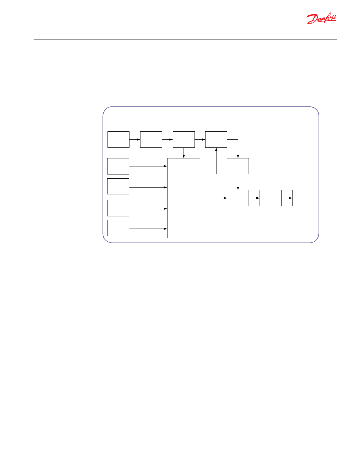
Application Block
Steering
Angle
Wheel
Speed
Wheel
Speed
Wheel
Speed
Wheel
Speed
Wheel
Speed
Limiter
Output
Driver
Offset
Reference
Speed
Calculations
Wheel
Spin
Calculator
Vehicle
Geometry
Turning
Circle
Offset
Mode
Speed
per
Wheel
P200076
System Description
ASC SSA
Overview
Concept and function
The Anti Spin Control Subsystem Application (ASC SSA) is designed for use with hydraulically propelled
vehicles incorporating single pump in conjunction with multiple motors. The subsystem application
software includes: an Application Block, Plug-in features, and a sample application.
User-programmable Anti Spin Control Subsystem Application
Benefits
The ASC SSA is a fully integrated, dual path control system solution that’s ready to be tailored to your
vehicle requirements. The software is made up of validated component software blocks that greatly
reduce vehicle testing time, provide responsive control and reduced project risk.
The graphical application code can be modified with GUIDE, using PLUS+1® Compliant products, such as
sensors, pumps and motors.
These PLUS+1® Compliant products are represented by functional software blocks. These blocks can be
dragged, dropped and connected to modify the ASC SSA to accommodate vehicle characteristics that are
different from those of the example application.
Compliance blocks that are pre-programmed for CAN communication between joysticks and PLUS+1
controllers are particularly easy to modify within the application.
Advanced control features and flexibility of plug-in design provide state of the art system performance.
Pre-configured service screens are provided to set up the software and adjust parameters.
®
©
Danfoss | May 2016 L1106431 | AB00000034en-US0301 | 5
Page 6

1
2
3
4
5
6
7
8
9
10
11
12
13
14
15
16
17
18
Battery (-)
Battery (+)
CAN 0 High
CAN 0 Low
Analog Input / CAN 0 Shield
Digital Input
Digital Input
5 V DC Sensor (+)
Digital Input
Digital Input
Digital Input
Digital Input
Digital Input / Analog Input
Sensor (-)
Digital Input / Analog Input
Digital Input / Analog Input
Digital Input / Analog Input / FreqIN
Digital Input / Analog Input / FreqIN
CAN 1 High
CAN 1 Low
Analog Input / CAN 1 Shield
Digital Input / Analog Input / FreqIN
Digital Input / Analog Input / FreqIN
Analog Input / Temp / Rheo
Digital Input / Analog Input
19
20
21
22
23
24
25
26
27
28
29
30
32
33
34
35
36
37
38
39
40
41
42
43
44
45
46
47
48
49
Digital Output
Digital Output
Digital Output / PVG Power 1
Digital Output / PVG Power 2
Digital Output / PVG Power 3
PWMOUT / Digital Out / PVG 1 OUT
PWMOUT / Digital Out / PVG 1 OUT
PWMOUT / Digital Out / PVG 1 OUT
PWMOUT / Digital Out / PVG 1 OUT
PWMOUT / Digital Out / PVG 2 OUT
PWMOUT / Digital Out / PVG 2 OUT
PWMOUT / Digital Out / PVG 2 OUT
PWMOUT / Digital Out / PVG 2 OUT
PWMOUT / Digital Out / PVG 3 OUT
Battery (+)
Battery (+)
Battery (+)
PWMOUT / Digital Out / PVG 3 OUT
Analog Input / Temp / Rheo
Analog Input / Temp / Rheo
Digital Input / Analog Input / FreqIN
Digital Input / Analog Input / FreqIN
Analog Input / Temp / Rheo
31
50
C1
Digital Output
Battery (+)
50 pins: Deutsch DRC connector
Batt.
12/24V
DC
+ -
S1
1
F1
C1: 09
C1: 08
Terminals
Sensor (+)
Terminals
Sensor (-)
Terminals
Batt. (-)
Terminals
Batt. (+)
C1: 01
C1: 02
C1: 27
C1: 23
C1: 17
C1: 16
C1: 47-50
C1: 15
C1: 31
Error LED
C1: 19
C1: 28
C1: 24
C1: 08
C1: 29
C1: 08
C1: 14
C1: 08
C1: 09
C1: 08
C1: 09
C1: 08
C1: 09
C1: 08
C1: 09
C1: 18
U
p
Pressure Sensor
PORT A
U
p
Pressure Sensor
PORT B
C1: 09
C1: 09
Rv
Rv
cw
Angle Sensor Front
C1: 08
C1: 09
C1: 30
Rv
Rv
cw
Angle Sensor Rear
C1: 08
C1: 09
PPU (left front)
4
2
3
5
PPU (right front)
4
2
3
5
PPU (left rear)
4
2
3
5
PPU (right rear)
4
2
3
5
2
2
2
P200075
System Description
ASC SSA
Overview
System application wiring
ASC SSA example application diagram
The ASC SSA example application has been designed to operate on the PLUS+1® MC050-012
microcontroller, but the ASC SSA can be modified to run on other PLUS+1® application hardware
modules.
6 | © Danfoss | May 2016 L1106431 | AB00000034en-US0301
Page 7

System Description
ASC SSA
Referenced documentation
Comprehensive technical literature online at powersolutions.danfoss.com
PLUS+1® software development tools
Subsystem application
Electronic product
PLUS+1® GUIDE Data Sheet
PLUS+1® GUIDE User Manual
PLUS+1® Service Tool User Manual
CG150 CAN/USB Gateway Interface Communicator Data Sheet
520L0708
10100824
520L0899
520L0945
The application software files are listed under Application file on page 11.
Anti spin Control Subsystem Application System Description
Anti spin Control Subsystem Application Data Sheet
Recommended Machine Electronic Control System Start Up Procedures
Subsystem Application Service Tool User Manual
Subsystem Application I/O Mapping User Manual
Application Block User Manual
Steering Plug-in GUIDE Programming User Manual
Machine State Plug-in User Manual
PLUS+1® microcontrollers and displays
PLUS+1® Controller Family Technical Information
DP2XX Graphical Display Family Technical Information
DP200 Series Graphical Terminals Technical Information
DP250 Series PLUS+1 Mobile Machine Displays Data Sheet
DP600 Series Graphical Terminals Technical Information
520L0719
L1026202
11023625
L1026137
520L0699
L1106431
L1106107
11010667
70055034
70054663
70047311
70047346
70047347
Sensors
MBS2250 Heavy Duty Pressure Transmitter (SAE Thread Version)
Data Sheet
MBS2250 Heavy-Duty Pressure Transmitter (DIN Thread Version)
Data Sheet
KPP Pulse Pickup (PPU) Technical Information
11005452
520L0801
11029257
Hydraulic product
High power axial piston pumps with electronic displacement control
H1 Axial Piston Pump, Size 078, Single Technical Information
H1 Axial Piston Pump, Size 089/100, Single Technical Information
H1 Axial Piston Pump, Size 115/130, Single Technical Information
H1 Axial Piston Pump, Size 147/165, Single Technical Information
©
Danfoss | May 2016 L1106431 | AB00000034en-US0301 | 7
11062169
11069970
11063346
11063347
Page 8

System Description
ASC SSA
Referenced documentation
High power axial piston pumps with electronic displacement control (continued)
H1 Axial Piston Pump, Size 115/130, 147/165, ISL Integrated Speed
Limitation Technical Information
Series 90 Axial Piston Pumps Technical Information
11053026
520L0603
High power variable displacement motors
H1B Bent Axis Variable Displacement Motors, Size 060/080/110
Technical Information
Series 51, Series 51-1 Bent Axis Variable Displacement Motors
Technical Information
Series 90 Axial Piston Motors Technical Information
11037153
520L0440
520L0604
Medium power variable axial piston pumps with electronic displacement control
H1 Axial Piston Pump, Size 045/053 Tandem Technical Information
H1 Axial Piston Pump, Size 045/053 Single Technical Information
H1 Axial Piston Pumps, Single and Tandem Basic Information
11063345
11063344
11062168
Medium power variable displacement motors
L and K Frame Variable Motors Technical Information
Series 40 Axial Piston Motors Technical Information
520L0627
520L0636
8 | © Danfoss | May 2016 L1106431 | AB00000034en-US0301
Page 9

System Description
ASC SSA
Control system
System development tools
PLUS+1® GUIDE (Graphical User Integrated Development Environment) is a desktop software
development tool used to create and customize application software to specific vehicle requirements.
GUIDE’s graphical editor allows easy development or modification of example applications by system
engineers without formal software development training.
Components and application blocks can be dragged from the component selector and dropped onto the
programming workspace for time-saving system design in the PLUS+1® GUIDE environment, generating
downloadable applications for all programmable PLUS+1® controllers and displays.
PLUS+1® Service Tool uses the CG150 Interface Communicator for programming PLUS+1® controllers via
CAN bus from a computer. Additionally, the PLUS+1® Service Tool features data logging capabilities with
oscilloscope and bar graph displays used for diagnostics and tuning. Graphical design features allow
development of specialized service screens to support applications created in PLUS+1® GUIDE.
The CG150 CAN/USB Gateway Interface Communicator serves as the interface between PLUS+1® modules
on the vehicle CAN network and a laptop USB port.
Application hardware
Software details
The SSA software may only be loaded onto keyed PLUS+1® application hardware. If the application
hardware key matches the Danfoss application software key the service tool permits the download to the
target application hardware.
Danfoss application key number is: 10106603
See product data sheet for controllers assembly part numbers.
GUIDE-programmable
PLUS+1® GUIDE programmable application software blocks. Graphical application code contained in the
PLUS+1® GUIDE programmable pages of the SSA can be modified by the user to tailor the application to
the specific needs of the vehicle or PLUS+1® controllers that are different from the example provided by
Danfoss.
Application block
The software application block assesses the wheel speed with consideration to vehicle geometry and
steer angle, wheel slip is identified and a corresponding output command signal is generated for
integration with the propel hardware and /or software configuration. The application block supports
manual enabling/disabling, operating tolerances for minimum motor speed, maximum motor speed and
steer angle.
Plug-ins
The Application Block accepts optional plug-in modules. Plug-ins provide design flexibility by allowing
enhanced features or performance. They may be used or deleted to conserve code space. Basic dual path
control functionality is preserved by replacing plug-ins with jumpers.
Plug-in Steering_PI Page
•
©
Danfoss | May 2016 L1106431 | AB00000034en-US0301 | 9
Page 10

System Description
ASC SSA
Control system
Steering plug-in converts vehicle geometry to values understood by the application block. Two
‒
and four wheel Ackerman steering geometry support is included, custom solutions may be
created and utilize socket.
Plug-in MachineState_PI Page
•
Machine State plug-in assesses command relative to propel conditions to establish an
‒
appropriate anti-spin operation. The plug-in utilizes pressure signals to determine slip wheel
relative to vehicle acceleration or deceleration.
I/O mapping
Input_Mapping page connects hardware input signals to appropriate software signals used within
•
the ASC application block and plug-ins.
Output_Mapping page connects the output command to physical hardware.
•
Parameters page applies configuration values for the anti spin operation.
•
Diagnostic page provides checkpoint visibility for the subsystem application.
•
Input mapping, output mapping, parameters, diagnostic
Downloading SSA software
PLUS+1® GUIDE license holders may visit the Danfoss web site, download the application file, and install
the enclosed software and documentation on their hard drive.
•
10 | © Danfoss | May 2016 L1106431 | AB00000034en-US0301
Page 11

System Description
ASC SSA
Control system
•
The application file contents are downloaded to your computer by clicking on the SSA exe.zip
link, clicking through the user acceptance agreement and installing the contents in the folder you
specify on your hard drive.
Application file
Application file for SSA software products contains all SSA graphical source code files, all required service
screens software files, and all software product documentation and user manuals associated with the
SSA. The software product documentation and user manuals (PDF) files are listed under Referenced
documentation on page 7: Subsystem application.
The Application file for the ASC SSA includes the following software files:
Software Installer Executable
Subsystem Application Software
Application Block Software
Steering Plug-in Software
Machine State Plug-in Software
Release Notes
.EXE 11081276_Vx
.P1P 11081276
.SCS 11096901
.SCS 11096922
.SCS 11096923
.HTML — —
Vehicle Geometry screen
Service Tool configurability. The Vehicle Geometry screen is used to configure the physical dimensions
and steering mechanism.
Vehicle Geometry screen and Diagnostic Navigator
©
Danfoss | May 2016 L1106431 | AB00000034en-US0301 | 11
Page 12

System Description
ASC SSA
Control system
System Overview screen
Service Tool configurability. The System Overview screen consolidates the most important about the
system, links provide access to additional detail.
System Overview screen and Diagnostic Navigator
12 | © Danfoss | May 2016 L1106431 | AB00000034en-US0301
Page 13

System Description
ASC SSA
Related products
Electronic product details
PLUS+1® microcontrollers
•
High speed DSP technology to process even the most complex applications
•
CAN-based communications for state-of-the art control performance
•
256K internal flash memory is recommended
PLUS+1® expansion modules
•
Expand control system capabilities with CAN-based Input/Output modules
•
12 and 24 pin housings with five possible configurations
•
Stackable design for optimum mounting flexibility
DP200 and DP250 displays
•
Cost effective alternative to existing analogue gauges
•
DP200 high-resolution monochrome displays fit every budget without compromising performance
•
DP250 high resolution color TFT (240x320 pixels, 15-bit color) displays are viewable in a wide range of
lighting conditions
•
Options featuring front USB 2.0 port for easy connection to PC-based service and diagnostic tools,
extended I/O for improved input design flexibility, real-time clock, and display heater
•
Customize the look and feel of engine monitoring and performance messages with Engine
Information Center (EIC) application software
Read and display engine operation and performance messages which are transmitted by the
‒
engine control module over a J1939 CANbus
Supports fifty engine and machine performance variables on up to four screens with up to four
‒
variables per screen
Soft keys at the front of the display provide the operator with easy navigation through diagnostic
‒
and engine information
©
Danfoss | May 2016 L1106431 | AB00000034en-US0301 | 13
Page 14

System Description
ASC SSA
Related products
DP600 display
•
Transflective TFT and DSTN, LCD display technologies, high resolution display, antiglare screen, and
sensor controlled backlighting
•
CAN, RS-232 and USB interfaces
•
Additional inputs for an external navigation button, which enables you to maneuver through all
terminal functions
MBS pressure sensors
•
Available in seven sizes ranging from to 2.5 bar to 600 bar [362 psi to 8,702 psi], load pressure is 10 to
20 times the measuring range
•
Temperature compensated, linearized, and laser calibrated
•
Available with DIN or UNF thread
KPP pulse pickup speed sensors
•
Outputs a digital pulse signal in response to the speed of a permanently magnetized speed ring on
the motor’s cylinder block or shaft
•
Ideal for low-speed measurement
•
For rugged outdoor, mobile, speed-sensing applications that do not allow contact with the rotating
shaft
14 | © Danfoss | May 2016 L1106431 | AB00000034en-US0301
Page 15

System Description
ASC SSA
Related products
Hydraulic product details
H1 axial piston variable pumps
•
Optimized for electrohydraulic control
•
Designed for improved operating efficiencies
•
Designed for short length and compact installation
Series 90 high power axial variable piston pumps
•
7 different displacements
•
Pressures up to 480 bar [6962 psi]
H1 medium power integral tandem axial piston pumps
•
2 integral tandem displacements
•
Optimized for electrohydraulic control
©
Danfoss | May 2016 L1106431 | AB00000034en-US0301 | 15
Page 16

System Description
ASC SSA
Related products
S42 medium power variable pumps
•
Pressures up to 415 bar [6019 psi]
•
Integral loop flushing
H1B bent axis variable displacement motors
•
Zero degree motor angle capability
•
Electric 2-position or electric proportional control
•
Higher corner HP/package size ratio
Series 51 bent axis variable displacement motors
•
Large displacement ratio (5:1)
•
Compact and lightweight
•
Pressures up to 480 bar [6962 psi]
Series 90 high power axial piston motors
•
Two-position motor
•
Short installed length
16 | © Danfoss | May 2016 L1106431 | AB00000034en-US0301
Page 17

System Description
ASC SSA
Related products
L and K frame medium power motors
•
Cartridge and SAE mounts available
•
Variable motor with 3.4:1 working displacement ratio
•
5 displacements in one compact package
Series 40 medium power motors
•
Short installed length
•
Pressures up to 345 bar [5000 psi]
Low speed high torque motors
•
High efficiency
•
Long life under extreme operating conditions
•
Smooth running over entire speed range
Anti spin control valve
•
Easy to service
•
Flexibility
©
Danfoss | May 2016 L1106431 | AB00000034en-US0301 | 17
Page 18

System Description
ASC SSA
18 | © Danfoss | May 2016 L1106431 | AB00000034en-US0301
Page 19

System Description
ASC SSA
©
Danfoss | May 2016 L1106431 | AB00000034en-US0301 | 19
Page 20

Danfoss
Power Solutions GmbH & Co. OHG
Krokamp 35
D-24539 Neumünster, Germany
Phone: +49 4321 871 0
Danfoss
Power Solutions ApS
Nordborgvej 81
DK-6430 Nordborg, Denmark
Phone: +45 7488 2222
Danfoss
Power Solutions (US) Company
2800 East 13th Street
Ames, IA 50010, USA
Phone: +1 515 239 6000
Danfoss
Power Solutions Trading
(Shanghai) Co., Ltd.
Building #22, No. 1000 Jin Hai Rd
Jin Qiao, Pudong New District
Shanghai, China 201206
Phone: +86 21 3418 5200
Products we offer:
Comatrol
www.comatrol.com
Schwarzmüller-Inverter
www.schwarzmuellerinverter.com
Turolla
www.turollaocg.com
Hydro-Gear
www.hydro-gear.com
Daikin-Sauer-Danfoss
www.daikin-sauer-danfoss.com
Bent Axis Motors
•
Closed Circuit Axial Piston
•
Pumps and Motors
Displays
•
Electrohydraulic Power
•
Steering
Electrohydraulics
•
Hydraulic Power Steering
•
Integrated Systems
•
Joysticks and Control
•
Handles
Microcontrollers and
•
Software
Open Circuit Axial Piston
•
Pumps
Orbital Motors
•
PLUS+1® GUIDE
•
Proportional Valves
•
Sensors
•
Steering
•
Transit Mixer Drives
•
Danfoss Power Solutions is a global manufacturer and supplier of high-quality hydraulic and
electronic components. We specialize in providing state-of-the-art technology and solutions
that excel in the harsh operating conditions of the mobile off-highway market. Building on
our extensive applications expertise, we work closely with our customers to ensure
exceptional performance for a broad range of off-highway vehicles.
We help OEMs around the world speed up system development, reduce costs and bring
vehicles to market faster.
Danfoss – Your Strongest Partner in Mobile Hydraulics.
Go to www.powersolutions.danfoss.com for further product information.
Wherever off-highway vehicles are at work, so is Danfoss. We offer expert worldwide support
for our customers, ensuring the best possible solutions for outstanding performance. And
with an extensive network of Global Service Partners, we also provide comprehensive global
service for all of our components.
Please contact the Danfoss Power Solution representative nearest you.
Local address:
Danfoss can accept no responsibility for possible errors in catalogues, brochures and other printed material. Danfoss reserves the right to alter its products without notice. This also applies to products
already on order provided that such alterations can be made without changes being necessary in specifications already agreed.
All trademarks in this material are property of the respective companies. Danfoss and the Danfoss logotype are trademarks of Danfoss A/S. All rights reserved.
©
Danfoss | May 2016 L1106431 | AB00000034en-US0301
 Loading...