

Unit Specification
(A )
(B )
(C )
R
E D
WH T
B
L K
C on n e c t o r
C W
P
O W E R
S IG
N AL
GRO U ND
P ot e n t i om e t e
r
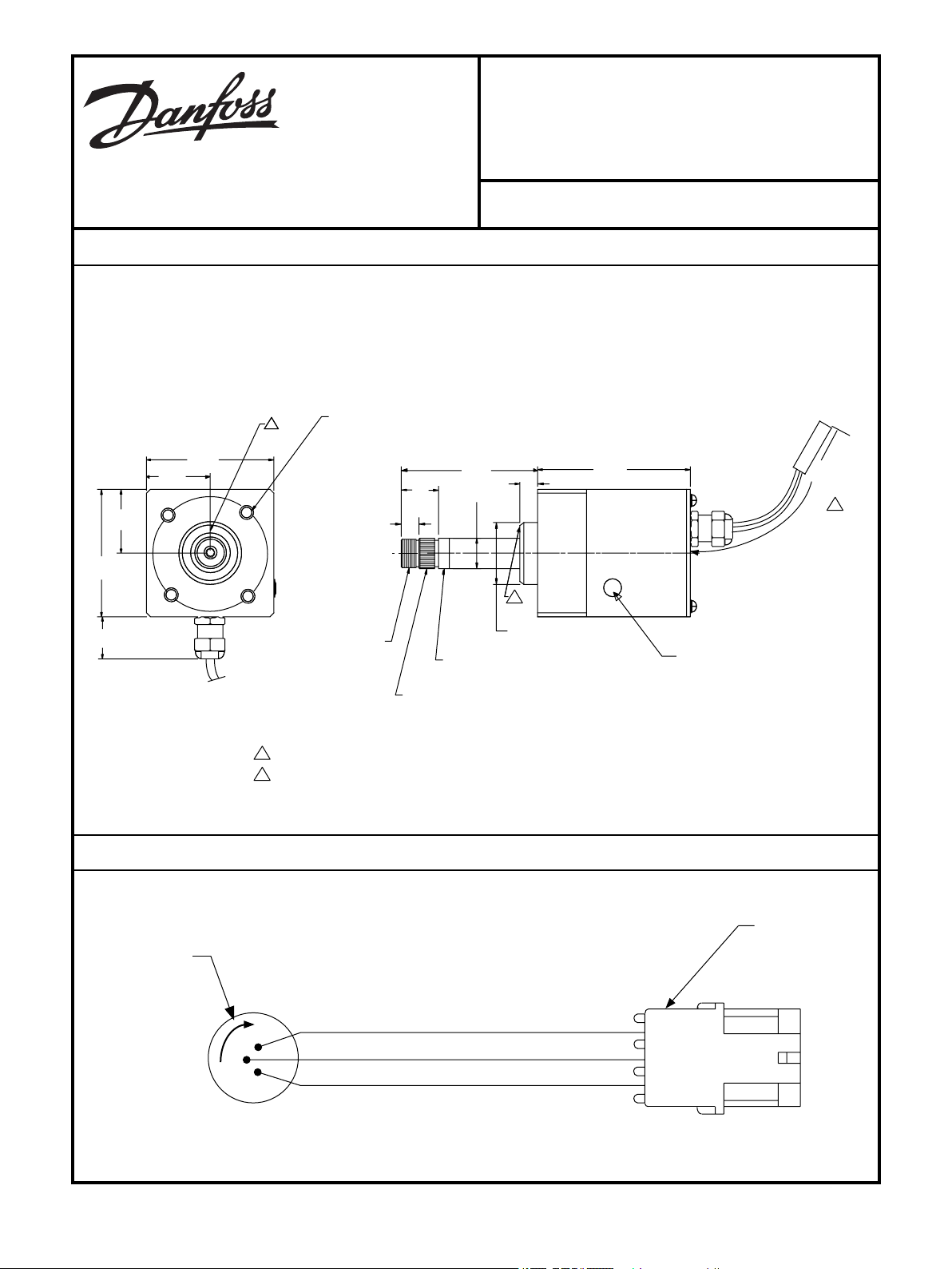
1824A
30
[1.18]
46
[1.81]
92
[3.62]
3/ 8-16 UNC-2B X 15 [0 .62 ] DP
4X ON A 82.55 [3.250] DIA B.C.
13 /16 -2O UN EF - 2 A T HRE AD
36 TO OT H SE RR AT IO
N
21.
79 [0 .858] O.D.
CO NE 1:1 9.2 6
21.79 [0. 858] MIN OR D I
A
230
± 25
[ 9
± 1]
10
9
[4.
31]
[0.50 ]
98
[3
.87]
26
[1.04]
22 [0 .88] DIA
13
13
[0.50 ]
46
[1.81]
92
[3.62]
43 [1.75]DI A
2
B ra ke f ric tio n a dju st
2046A
Ma ti ng c onne ct or p ar t numb er K08 62 0
1
1
2
2
Note: Line up mark on shft with mark on
housing for electrical center of sensor.
1090199
STS Steering Sensor
3500 Annapolis Lane North, Minneapolis, MN 55447
Telephone: (763) 509-2084 Fax: (763) 559-0108
GENERAL DESCRIPTION
The STS Steering Sensor is intended to provide an electrical steer signal input to a control device such as a DC2 or
SUSMIC10. The signal is generated by rotary shaft motion and is converted to an electrical output by a long life
potentiometer. The shaft is suitable for mounting on available commercial steering wheels. This sensor is intended
to be used outdoors on mobile equipment. This is a friction-held device. Cable assembly comes out rear of unit.
Dimensions of the 1090199 STS Steering Sensor in millimeters [inches].
ISSUE: 2 DATE: October 2005
CONNECTION DIAGRAM
K23756 UNIT SPEC
© Danfoss, 2013-09 K23756 UNIT SPEC 1
1 OF 2
© Copyright 2005, Sauer-Danfoss.
All rights reserved. Contents subject to change.
TECHNICAL DATA
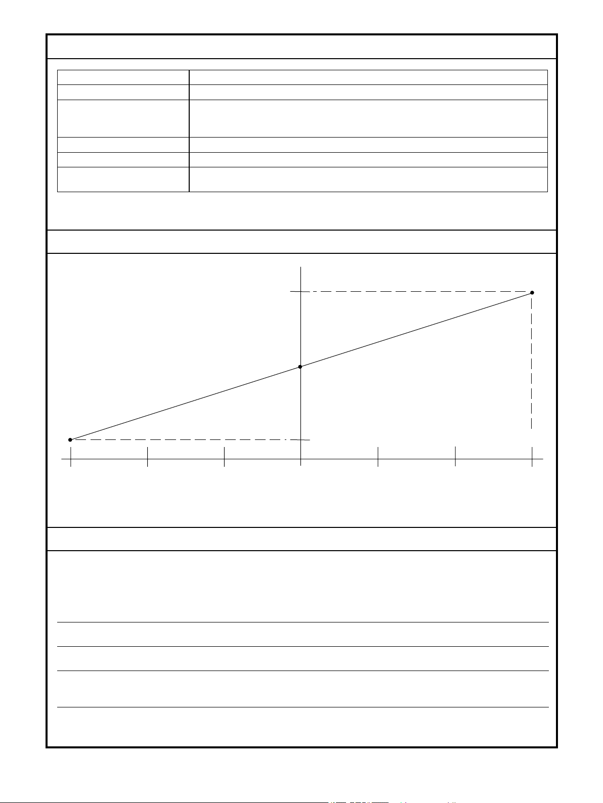
135 9 0 45 0
45 90 135
Sha ft di spl ac em ent
( De gre e s)
VR EF ( % In pu t)
10 %
50 %
9
0%
C lo ckw i seC ou nt e rc lo ckwi s e
1823A
Input voltage 30 V DC maximum
Shaft rotation ±135° travel
Output at: CW: 90 ± 6% of supply voltage
Center: 50 ± 10% of supply voltage
CCW: 10 ± 6% of supply voltage
Sensor resistance 1000 Ω
ensor wattage 1 watt maximum at 40° C
S
Shaft friction characteristic 3.4 N•m [30 lbf•in] torque maximum
F
actory set at 2.8 N•m [25 lbf•in]
OUTPUT CHARACTERISTICS
INSTALLATION
Apply 68 ± 6.8 N•m [50 ± 5 lbf•ft] of torque to the nut that secures the steering wheel to the steering sensor. This
torque specification conforms to SAE J511 FEB94/ISO 5010 (general requirements 3.1 and 3.2 also all steering systems
8.1.1) pertaining to steering for off-road machines with rubber tires.
WWARNING
Take appropriate diagnostic and failure mode corrective action. This control device has a positive voltage reference.
A wiring short may produce an unintended output signal causing unwanted output and machine motion.
WWARNING
Provide an emergency shut down and/or braking system sufficient to immediately stop the system or vehicle. A
sensor failure may cause an output which could activate a valve or pump. If this occurs, the apparatus may move,
possibly endangering people or equipment.
© Danfoss, 2013-09 K23756 UNIT SPEC 1
 Loading...