

Data sheet
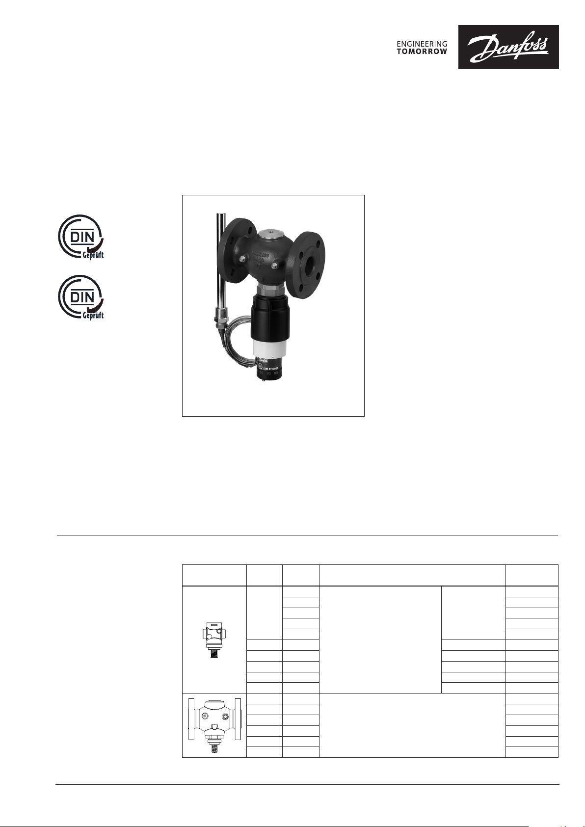
TR(TW)700
Temperature controller AVT with safety temperature monitor
STM/VG(F) (PN25)
Description
STW871
STM / VGF
STM/VG(F) and STM/AVT/VG(F) are self-acting
proportional temperature controllers used
for temperature control and temperature
monitoring of drinking water, water and water
glycol mixtures for heating and district heating
systems.
VG - valve with external thread
VGF - valve with flange
Controller closes on rising temperature.
The controllers are:
• Type-tested acc. to EN 14597 and protect
against exceeding temperatures:
Applications:
- District heating systems acc. to DIN 4747
- Heating systems acc. to EN 12828 (DIN 4751)
and EN 12953-6 (DIN 4752)
- Water heating systems for drinking and
industrial waters acc. to DIN 4753
Main data:
• DN 15-50
• kVS 0.4 -25 m3/h
• PN 25
• Setting ranges:
- STM monitor:
20 … 75 °C / 40 … 95 °C / 30 … 110 °C
- AVT thermostatic actuator:
− 10 … 4 0 °C / 20 … 70 °C /
40 … 90 °C / 60 … 110 °C
and
10 … 45 °C / 35 … 70 °C /
60 … 100 °C / 85 … 125 °C
• Temperature:
- Circ. water/glycolic water up to 30 %:
2 … 150 °C
• Connections:
- Ext. thread (weld-on, thread and flange
tailpieces)
- Flange
• Flow and return mounting
Ordering
Example 1 - STM / VG(F) controller:
Safety temperature monitor;
DN 15; kVS 1.6 , PN 25;
limit range 30 …110 °C;
T
150 °C; ext. thread
max
- 1× VG DN 15 valve
Code No: 065B0772
- 1× STM monitor, 30 … 110 °C
Code No: 065-0608
Option:
- 1× Weld-on tailpieces
Code No: 003H6908
All products will be delivered
separately.
© Danfoss | 2020.07
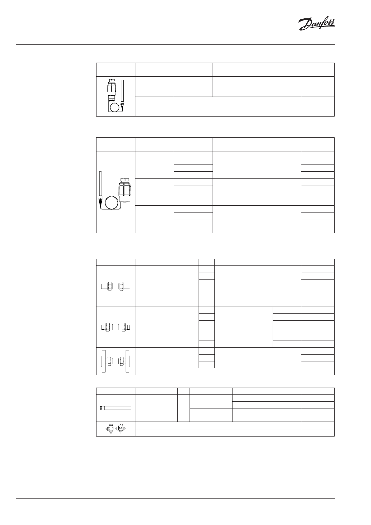
VG, VGF valve
Picture
DN k
(mm) (m3/h)
15
20 6.3 G 1 A 065B0775
25 8.0 G 1 ¼ A 065B0776
32 12.5 G 1 ¾ A 065B0777
40 16 G 2 A 065B0778
50 20 G 2 ½ A 065B0779
15 4.0
20 6.3 065B0781
25 8.0 065B0782
32 12.5 065B0783
40 20 065B0784
50 25 065B0785
VS
0.4
1.0 065B0771
1.6 065B0772
2.5 065B0773
4.0 065B07 74
Cylindrical external thread acc. to
Connection Code No.
G ¾ A
ISO 228/1
Flanges PN 25, acc. to EN 1092-2
AI173286479061en-000602 | 1
065B0770
065B0780
Data sheet Temperature controller AVT with safety temperature monitor STM/VG(F) (PN 25)
Ordering (continuous)
Example 2- STM/AVT/ VG(F)
controller:
Temperature controller with safety
temperature monitor; DN 15, kVS 1.6 ;
PN 25; limit range 30 … 110 °C;
setting range 40 … 90 °C;
T
150 °C; ext. thread
max
- 1× VG DN 15 valve
Code No: 065B0772
- 1× STM monitor, 30 … 110 °C
Code No: 065-0608
- 1x AVT thermostatic actuator,
40 … 90 °C
Code No: 065-0598
- 1× K2 Combination piece
Code No: 003H6855
Option:
- 1× Weld-on tailpieces
Code No: 003H6908
All products will be delivered
separately.
STM Safety temperature monitor (actuator)
Picture For valves
DN 15-50
1)
conic male t hread EN 10226 -1
Limit range
(°C)
30 … 11 0
20 … 75 065-0609
40 … 95 065-0610
AVT Thermostatic actuator
Picture For valves
DN 15-2 5
DN 32-50
DN 15-50
1)
conic male t hread EN 10226 -1
2)
without imme rsion pocket
Setting range
(°C)
–10 … +40
20 … 70 065-0597
40 … 90 065-0598
60 … 110 065-0599
−10 … +4 0
20 … 70 065-0601
40 … 90 065-0602
60 … 110 065-0603
10 … 45
35 … 70 065-0605
60 … 100 065-0606
85 … 12 5 065-0607
Temperature sensor with brass immersion
pocket, length, connection
210 mm, R ¾
Temperature sensor with brass immersion
pocket, length, connection
170 mm, R ½
210 mm, R ¾
255 mm, R ¾
1)
1)
1)
1) 2)
Code No.
065-0608
Code No.
065-0596
065-0600
065-0604
Accessories for valves
Picture Type designation DN Connection Code No.
15
20 003H6909
Weld-on tailpieces
External thread tailpieces
Flange tailpieces
25 003H 6910
32 003 H69 11
40 065B2006
50 065B2007
15
20 R ¾ 003H6903
25 R 1 003H6904
Conical ex t. thread acc. to
32 R 1¼ 003H6905
40 R 1½ 065B2004
50 R 2 065B2005
15
20 003H 6916
25 003 H6917
EN 10226-1
Flanges PN 25, acc. to EN 1092-2
-
R ½ 003H69 02
Accessories for thermostats
Picture Type designation PN For controllers Material Code No.
AVT/VG(F) DN 15-25
Immersion pocket 25
Combination piece K2 003H6855
Combination piece K3 003H6856
1)
Not for AVT t hermostatic actuator code n umbers: 065-0604, 065-0605, 065-0606, 065-0607
AVT/VG(F) DN 32-50
STM/VG(F) DN 15-50
Stainless steel, mat. No. 1.4571 065 -4415
Stainless steel, mat. No. 1.4435 06 5-4 417
Brass 06 5-4 414
Brass 065 -4416
003H6908
003H6 915
1)
1)
1)
1)
2 | AI173286479061en-000602
© Danfoss | 2020.07
Data sheet Temperature controller AVT with safety temperature monitor STM/VG(F) (PN 25)
Ordering (continuous)
Technical data
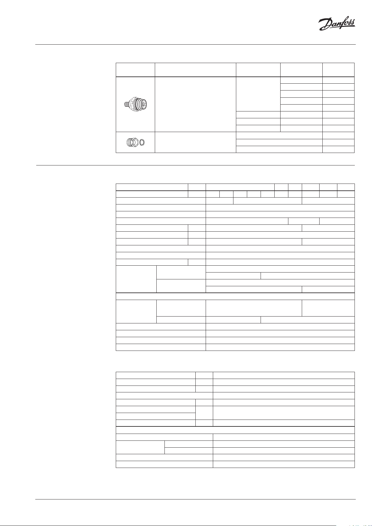
Service kits
Picture Type designation
Valve insert
Housing of sensor stuffing box
DN k
(mm) (m3/h)
15
20 6.3 0 03H6 874
25 8.0 003H6875
32 / 40 / 50 12.5 / 16 / 20 / 25 003H6876
for sensors
AVT 170 R ½ 065- 4420
AVT 210, 255 R ¾ 065 -4421
VS
Code No.
0.4 003H6869
1.0 0 03H6870
1.6 003H6871
2.5 003H6872
4.0 003H6873
VG, VGF valves
Nominal diameter DN 15 20 25 32 40 50
k
value m3/h 0.4 1.0 1.6 2. 5 4.0 6.3 8 12. 5 16/2 0 1)20/25
VS
Stroke 3 5 10
Control ratio > 1:50
Control characteristic linear
Cavitation factor z ≥ 0.6 ≥ 0.55 ≥ 0.5
Leakage acc. to standard IEC 534 % of k
VS
Nominal pressure PN 25
Max. differential pressure bar 20 16
Medium Circulation water / glycolic water up to 30 %
Medium pH Min. 7, max. 10
Medium temperature
°
C 2 … 150
valve
Connections
tailpieces
Materials
Valve body
thread Red bronze CuSn5ZnPb (Rg5)
flange - Ductile iron EN-GJS- 400-18-LT (GGG 40.3)
Valve seat Stainless steel, mat. No. 1.4571
Valve cone Dezincing free brass CuZn36Pb2As
Sealing EPDM
Pressure relieve system Piston
1)
Flange valve b ody
≤ 0.02 ≤ 0.05
External thread
- Flange
Weld-on and external thread
Flange -
Ductile iron
EN-GJS-400-18-LT
(GGG 40.3)
1)
© Danfoss | 2020.07
STM Safety temperature monitor (actuator)
Limit range X
s
Time constant T acc. to EN 14597 s max. 100
Gain K
s
Max. adm. temperature at sensor 80 °C above maximum setpoint
Max. amb. temperature at thermostat °C 0 … 70
Nominal pressure sensor
Nominal pressure immersion pocket
Capillary tube length m 5
Materials
Temperature sensor Cooper
Immersion pocket
Ms design Brass, nickel-plated
Stainless steel design mat. No. 1.4435
Handle for temp. setting Polyamide, glass fiber-reinforced
Scale carrier Polyamide
°C
20 … 75 / 40 … 95 / 30 … 110
mm/°K
PN 25
0.3
AI173286479061en-000602 | 3
Data sheet Temperature controller AVT with safety temperature monitor STM/VG(F) (PN 25)
Technical data (continuous)
Application principles
AVT Thermostatic actuator
Setting range X
Time constant T acc. to EN 14597 s max. 50 (170 mm, 210 mm), max. 30 (255 mm)
Gain K
Max. adm. temperature at sensor 50 °C above maximum setpoint
Max. amb. temperature at thermostat °C 0 … 70
Nominal pressure sensor
Nominal pressure immersion pocket
Capillary tube length m 5 (170 mm, 210 mm), 4 m (255 mm)
Materials
Temperature sensor Cooper
Immersion pocket
Handle for temp. setting Polyamide, glass fiber-reinforced
Scale carrier Polyamide
1)
for sensor 170 and 210 mm
s
s
Ms design Brass, nickel-plated
1)
Stainless steel design Mat. No. 1.4571 (170 mm), mat. No. 1.4435 (210 mm)
°C
mm/°K
PN 25
−10 … 40 / 20 … 70 / 40 … 90 / 60 … 110
10 … 45 / 35 … 70 / 60 … 100 / 85 … 125
0.2 (170 mm); 0.3 (210 mm); 0.7 (255 mm)
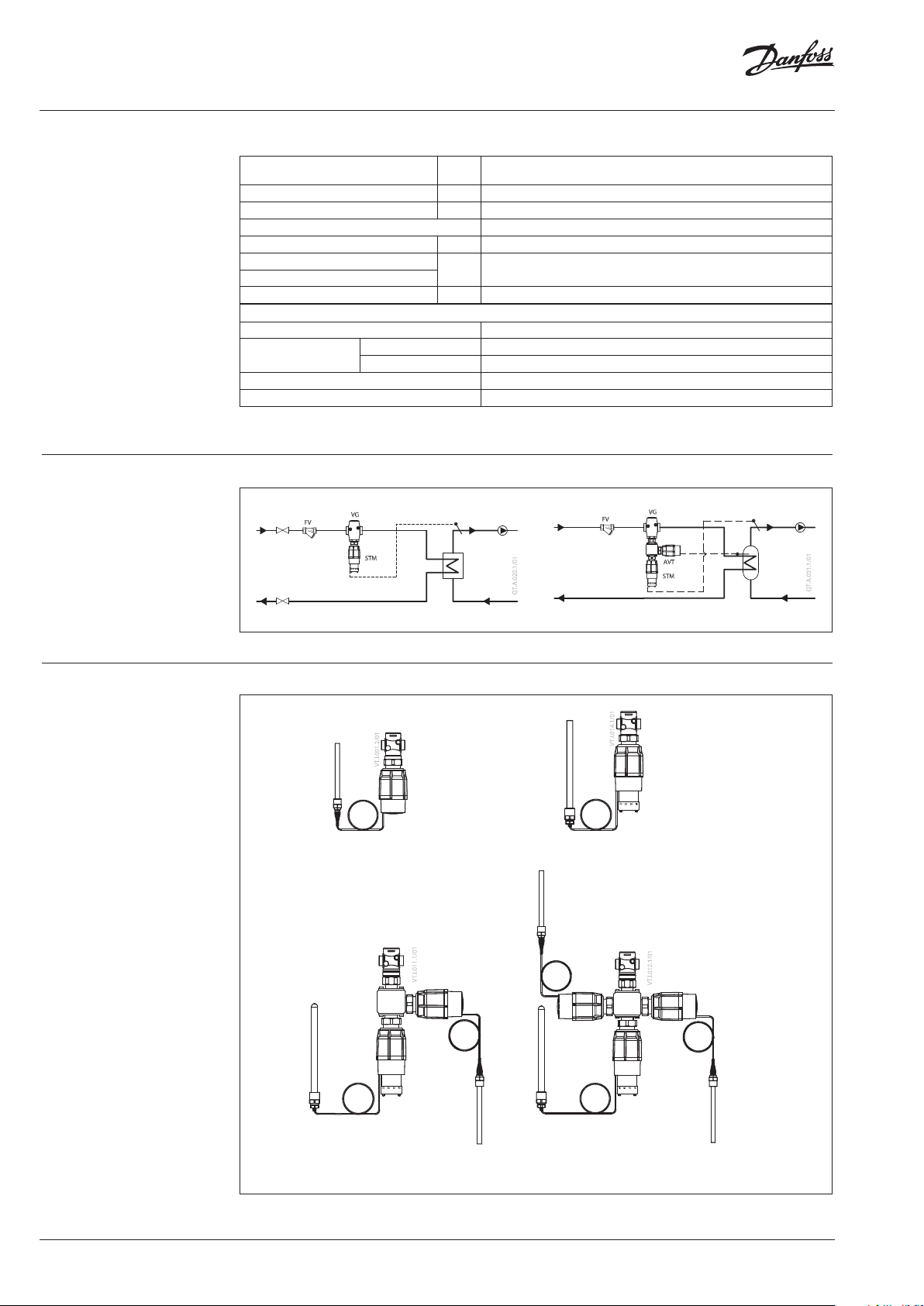
Combinations
AVT / VG
- temperature controller
STM / AVT / VG
- temperature controller with
safety temperature monitor
STM / VG
- safety temperature monitor
STM / AVT / AVT /VG
- two temperature controllers with
safety temperature monitor
4 | AI173286479061en-000602
© Danfoss | 2020.07

Data sheet Temperature controller AVT with safety temperature monitor STM/VG(F) (PN 25)
Installation positions
Temperature controller and safety temperature
monitor
Temperature controller AVT / VG(F) and safety
temperature monitor STM / VG(F) can be
installed in any position.
Temperature sensor
The place of installation must be chosen in a way
that the temperature of the medium is directly
taken without any delay. Avoid overheating of
temperature sensor. The temperature sensor
must be immersed into the medium in its full
length.
Temperature sensors 170 mm R ½ and 210 mm R ¾
- The temperature sensor may be installed in
any position.
Temperature sensor 255 mm R ¾
- The temperature sensor must be installed as
shown on the picture.
Pressure temperature
diagram
© Danfoss | 2020.07
EN-GJS- 400-18 -LT (GGG 40.3) PN 25
CuSn5ZnPb (Rg5) PN 25
Maximum allowed operating pressure as a function of medium temperature (according to EN 1092-2 and EN 1092-3).
AI173286479061en-000602 | 5

Data sheet Temperature controller AVT with safety temperature monitor STM/VG(F) (PN 25)
Valve sizing
6 | AI173286479061en-000602
Given data:
P
= 14 kW
max
t = 20 K
pv = 0.15 bar
P
- heating power (kW)
max
t -temperature difference (K)
pv - differential pressure across the valve
Maximum flow Q
calculated according to formula:
max
Q
max
Q
= 0.6 m3/h
max
(m3/h) through the valve is
max
86.0P
86.014
t
20
kv value is calculated according to formula:
Q
max
k
v
p
6.0
15.0
V
kv = 1.5 m3/h
Chosen kVS = 1.6 m3/h
or read from the sizing diagram by taking a line
through Q scale (0.6 m3/h) and pv scale (0.15 bar)
to intersect kv-scale at 1.5 m3/h
Chosen kvs = 1.6 m3/h
Solution:
The example selects:
1) ext. thread valve VG DN 15, kVS value 1.6 or
2) flange valve VGF DN 15, kVS value 1.6
© Danfoss | 2020.07

Data sheet Temperature controller AVT with safety temperature monitor STM/VG(F) (PN 25)
Design
STM / VGF
1. Valve VG(F)
2. Valve insert
3. Pressure relieved valve cone
4. Valve stem
5. Union nut
6. Safety temp. monitor STM
7. Thermostat stem
8. Setting spring for
temperature control
9. Handle for limit setting,
prepared for sealing
10. Scale carrier
11. Capillary tube
12. Temperature sensor
13. Immersion pocket
14. Safety spring
AVT / VG(F)
1. Valve VG(F)
2. Valve insert
3. Pressure relieved valve cone
4. Valve stem
5. Union nut
6. Thermostatic actuator AVT
7. Thermostat stem
8. Bellows
9. Setting spring for
temperature control
10. Handle for temperature
setting, prepared for sealing
11. Scale carrier
12. Capillary tube
13. Flexible protected pipe
(only at AVT 255 mm)
14. Temperature sensor
15. Immersion pocket
16. Sensor stuffing box
17. Housing of sensor stuffing
box
AVT 255
AV T 170
AV T 210
© Danfoss | 2020.07
AI173286479061en-000602 | 7

Data sheet Temperature controller AVT with safety temperature monitor STM/VG(F) (PN 25)
Function
Mode of Operation
The safety temperature monitor is
proportional temperature controller which
controls temperature and protects the system
against exceeding temperatures. The valve
cone is soft sealed and pressure relieved.
Safety Temperature Monitor (STM/VG(F))
- Function
In case the temperature at the temperature
sensor exceeds the adjusted set point, safety
temperature monitor interrupts energy
supply by closing the valve. As soon as the
temperature at the temperature sensor drops,
the valve opens automatically.
Handle for limit setting can be sealed.
- Extended safety function
If there is a leakage in the area of the
temperature sensor, the capillary tube, or the
thermostat, the valve closes by a safety spring
in the safety thermostat. In this case safety
temperature monitor (actuator) must be
replaced.
- Physical Function Principle
The safety temperature monitor operates
in accordance with the liquid expansion
principle. The temperature sensor, the
capillary tube and the bellows are filled with
liquid. As the temperature at the temperature
sensor rises, the liquid expands, the
thermostat stem moves out and closes the
valve.
Temperature Controller (AVT/VG(F))
- Function
By increasing of medium temperature valve
cone moves towards the seat (valve closes),
by decreasing of medium temperature valve
cone moves away from the seat (valve opens).
Handle for temperature setting can be sealed.
- Physical Function Principle
Medium temperature changes cause pressure
changes in temperature sensor. Resulting
pressure is being transferred through the
capillary tube to the bellows. Bellows moves
thermostat stem and opens or closes the
valve.
Settings
Temperature setting (AVT)
Temperature setting is being done by the
adjustment of the setting spring for temperature
control. The adjustment can be done by means
of handle for temperature setting and/or
temperature indicators.
Adjustment diagram Temperature setting
Relation between scale numbers 1-5 and closing
temperature.
Note: The va lues given are approximate
AVT Thermostat ... 170 mm, 210 mm
AVT Thermostat ... 255 mm
Limit setting (STM / VG(F)
Limit setting is being done by the adjustment of
the setting spring for temperature control. The
adjustment can be done by means of handle for
limit setting and/or temperature indicators.
8 | AI173286479061en-000602
Note:
STM Safety te mperature monitor (actuato r):
temperature sca le is already written on th e product
© Danfoss | 2020.07

Data sheet Temperature controller AVT with safety temperature monitor STM/VG(F) (PN 25)
Dimensions
L
AVT/VG DN15-50
L
L
1
6
H
5
H
150
3
1
H
H
Ø 76
AVT
AVT/VGF DN 15-50
L
1
6
H
5
H
2
H
ST M/ VG DN15- 50
DN L L1H1H2H3H4H5H
15 65 130 180 224 229 274 34 47
20 70 150 180 224 229 2 74 34 52
25 75 160 180 224 229 274 37 57
32 10 0 180 221 266 221 266 62 70
40 110 200 221 266 2 21 266 62 75
50 13 0 230 221 266 221 266 62 82
Ø 9.5
174
ST M/ VGF DN15 -50
Ø 12
170
194
4
H
Ø 82
STM
6
223
AVT, STM
Typ e
sensor 170 mm
sensor 210 mm 1.5 2.6
sensor 255 mm 1.6 -
Ø 16
215
Ø 19
AVT STM
kg
Weight
1.4 -
Ø 16
266
© Danfoss | 2020.07
SW 17
AV T 170
M14×1
Immersion pocket
6
AVT 170
SW 22
R ½
SW 22
M22×1
AVT 210 / STM
10
SW 27
R ¾
AVT 210 / STM
Immersion pocket
AI173286479061en-000602 | 9
SW 22
R ¾
AVT 255

Data sheet Temperature controller AVT with safety temperature monitor STM/VG(F) (PN 25)
Dimensions (continuous)
L
L
L
1
H
2
H
1
H
2
H
H
1
H
H
2
H
L
1
H
H
2
H
H
VG DN 15-25
VG DN 32-50
VG
DN
L H H
mm
15 65 80 34 46 0.7
20 70 80 34 46 0.8
25 75 83 37 46 0.9
32 100 151 63 88 3.0
40 110 151 63 88 3.1
50 130 151 63 88 3.8
L
3
d
SW
1)
DN R
15 ⁄ 32 (G ⁄A) 21 130 131 139 65 14 4
20 ⁄ 41 (G 1A ) 26 150 14 4 154 75 14 4
25 1 50 (G 1⁄A) 33 16 0 160 159 85 14 4
32 1⁄ 63 (G 1¾A) 42 - 177 184 100 18 4
40 1 ⁄ 70 (G 2A) 47 - 195 204 110 18 4
50 2 82 (G 2½A) 60 - 252 234 125 18 4
1)
Conical ex t. thread acc. to EN 10226-1
2)
Flanges PN 25, acc. to EN 1092-2
H
1
2
R
SW d L
Weight
L
2
VGF DN 15-25
VGF
(kg)
DN
Note: other flan ge dimensions - see table for tail pieces
SW
2)
1
mm
L H H
mm
15 13 0 144 48 96 3.3
20 150 149 53 96 4 .1
25 16 0 154 58 96 4.7
32 180 158 70 88 7. 5
40 200 163 75 88 9.0
50 230 17 1 83 88 11.1
L
1
SW
L2L
k d
3
1
n
2
VGF DN 32-50
H
Weight
2
(kg)
d
2
45°
n
k
10 | AI173286479061en-000602
SW 22 (R ½)
SW 27 (R ¾)
R ½; R ¾
Housing of sensor
M 14×1 (R ½)
M 22×1 (R ¾)
stuffing box
85
109
30 (R ¾)
25 (R ½)
Combination piece K2
108
109
Combination piece K3
© Danfoss | 2020.07

Data sheet Temperature controller AVT with safety temperature monitor STM/VG(F) (PN 25)
© Danfoss | 2020.07
AI173286479061en-000602 | 11

Danf
already on order pro
All trademarks in this material are property of the respec
Data sheet Temperature controller AVT with safety temperature monitor STM/VG(F) (PN 25)
oss can accept no responsibility for possible errors in catalogues, brochures and other printed material. Danfoss reserves the right to alter its products without notice. This also applies to products
vided that such alterations can be made without subsequential changes being necessary eady agreed.
12 | AI173286479061en-000602
tive companies. Danfoss and the Danfoss logotype are trademarks of Danfoss A/S. All rights reserved.
© Danfoss | DHS-SRMT/SI | 2020.07
 Loading...