

Instructions
STLV STLS STLV STLS STLV STLS
STLV, STLS
(STL/VG) (STL/VGF) (STL/VGS)
DN 15 - 25 DN 32 - 50 DN 15 - 25
ENGLISH
DEUTSCH
POLSKI
73695180 DH-SMT/SICO 04 / 2006 VI.JK.G1.7R 1
Safety temperature limiter (Actuator)
STLV, STLS
Schutz-Temperatur-Begrenzer (Antrieb)
STLV, STLS
Bezpiecznik temperatury (siłownik)
STLV, STLS
(STL/AVT/VG) (STL/AVT/VGF) (STL/AVT/VGS)
DN 15 - 25 DN 32 - 50 DN 15 - 25
Page 2
www.danfoss.com
Seite 2
www.danfoss.de
Strona 2
www.danfoss.pl
(STL/AVT/AVT/VG) (STL/AVT/AVT/VGF) (STL/AVT/AVT/VGS)
DN 15 - 25 DN 32 - 50 DN 15 - 25

ENGLISH DEUTSCH POLSKI
STLV, STLS
Contents
Safety Notes 3
Definition of applications 4
- Application examples 5
Assembly 6
- Admissible Installation
Positions 6
- Installation Location and
Installation Scheme 8
- Valve Installation 9
- Mounting of safety
temperature limiter
(actuator) 10
- Mounting of temperature
actuator 11
- Insulations 12
- Dimensions, Weights 12
Start-up 14
- Filling the system,
first start-up 14
- Leak and pressure tests 15
- Putting out of operation 15
- Settings 16
- Temperature setting 16
- Resetting of safety
temperature limiter 17
- Safety function 18
Inhalt
Sicherheitshinweise 3
Bestimmungsgemäße
Verwendung 4
- Anwendungsbeispiele 5
Montage 6
- Zulässige Einbaulagen 6
- Einbauort und
Einbauschema 8
- Ventileinbau 9
- Einbau des SchutzTemperatur-Begrenzers
(Antrieb) 10
- Einbau des Thermostats 11
- Isolierung 12
- Abmessungen, Gewicht 12
Inbetriebnahme 14
- Befüllen des Systems,
erste Inbetriebnahme 14
- Dichtigkeitsprüfung /
Druckprüfung 15
- Außerbetriebnahme 15
- Einstellungen 16
- Temperatureinstellung 16
- Entriegeln des SchutzTemperatur-Begrenzers 17
- Sicherheitsfunktion 18
Spis treści
Warunki bezpieczeństwa 3
Zastosowanie 4
- Przykłady zastosowań 5
Montaż 6
- Dopuszczalne pozycje
montażu 6
- Miejsce i schemat
montażu 8
- Montaż zaworu 9
- Montaż bezpiecznika
temperatury (siłownika) 10
- Montaż siłownika
termicznego
(regulacyjnego) 11
- Izolacja 12
- Wymiary, ciężar 12
Uruchomienie 14
- Napełnienie układu,
pierwsze uruchomienie 14
- Próby szczelności i
ciśnienia 15
- Odłączenie zaworu 15
- Nastawy 16
- Nastawa temperatury 16
- Resetowanie
bezpiecznika
temperatury 17
- Funkcja bezpieczeństwa 18
2

ENGLISH DEUTSCH POLSKI
STLV, STLS
Safety Notes
Prior to assembly and
commissioning to avoid
injury of persons and
damages of the devices, it
is absolutely necessary to
carefully read and observe
these instructions.
Necessary assembly, startup, and maintenance work
must be performed only
by qualified, trained and
authorized personnel.
Prior to assembly and
maintenance work on the
controller, the system must
be:
- depressurized,
- cooled down,
- emptied and
- cleaned.
Please comply with the
instructions of the system
manufacturer or system
operator.
Sicherheitshinweise
Um Schäden an Personen
und Geräten zu vermeiden,
sind vor jeder Montage
und Inbetriebnahme die
vorliegenden Vorschriften
sorgfältig durchzulesen und
zu beachten.
Erforderliche Montage,
Inbetriebnahme- und
Wartungsarbeiten dürfen
nur von sachkundigen,
geschulten und autorisierten
Personen durchgeführt
werden.
Vor Montage - und
Wartungsarbeiten am Regler
muss die Anlage:
- drucklos,
- ausgekühlt,
- entleert und
- ggf. gereinigt werden.
Die Vorgaben des
Anlagenherstellers bzw.
Anlagenbetreibers sind zu
beachten.
Warunki bezpieczeństwa
W celu uniknięcia zranienia
osób i uszkodzenia urządzeń
należy bezwzględnie przed
montażem i uruchomieniem
zaworu zapoznać się
dokładnie z niniejszą
instrukcją.
Czynności związane z
montażem, uruchomieniem
i obsługą mogą być
dokonywane wyłącznie
przez osoby uprawnione
i odpowiednio
wykwalifikowane.
Przed montażem i obsługą
konserwacyjną regulatora
należy:
- zrzucić ciśnienie,
- ostudzić układ,
- opróżnić układ,
- oczyścić.
Prosimy stosować się do
instrukcji producenta lub
operatora układu.
3

ENGLISH DEUTSCH POLSKI
STLV, STLS
Definition of Application
Controller STLV is
combination of valve VG(F)
and actuator STL mounted
together.
Controller STLS is
combination of valve VGS
and actuator STL mounted
together.
Safety temperature
limiter (actuator) STL is, in
combination with Danfoss
valves (STL / VG(F), VGS)
and Danfoss controller
combinations (STL / AVT
/ VG(F), VGS), used for
temperature control and
temperature limitation of
drinking water, water and
water glycol mixtures for
heating and district heating
systems.
The controllers STL / VG(F),
VGS and STL / AVT / VG(F),
VGS are:
- Type-tested acc. to
EN 14597
and protect against
exceeding temperatures:
- District heating systems
acc. to DIN 4747
- Heating systems acc. to
EN12828 (DIN 4751) and
EN12953-6 (DIN 4752)
- Water heating systems for
drinking and industrial
waters acc. to DIN 4753
The technical parameters on
the product labels determine
the use.
Bestimmungsgemäße
Verwendung
Der Schutz-TemperaturBegrenzer STLV ist eine
Kombination aus dem Ventil
VG(F) und dem Antrieb STL.
Der Schutz-TemperaturBegrenzer STLS ist eine
Kombination aus dem Ventil
VGS und dem Antrieb STL.
Der Schutz-TemperaturBegrenzer (Antrieb) Typ STL
wird zusammen mit den
Ventilen VG(F) und VGS und
dem Thermostaten AVT für
die Temperaturregelung
und Temperaturbegrenzung
vorwiegend in Heizungs- und
Trinkwassererwärmungsanlag
en, sowie Anlagen mit GlykolWassergemischen, die an die
Fernwärme angeschlossen
sind, eingesetzt.
Die Kombinationen STL /
VG(F), VGS und STL / AVT /
VG(F), VGS sind:
- typgeprüft nach EN 14597.
Die technischen Daten auf
den Typenschildern sind für
die Verwendung maßgebend.
Zastosowanie
Regulator STLV jest
połączeniem zaworu VG(F) i
siłownika STL.
Regulator STLS jest
połączeniem zaworu VGS i
siłownika STL.
Bezpiecznik temperatury
(siłownik) STL, w połączeniu
z zaworami Danfoss (STL/
VG(F), VGS) i regulatorami
Danfoss (STL/AVT/VG(F),
VGS), służy do regulowania
i ograniczenia temperatury
wody lub mieszaniny wody
z glikolem w instalacjach
grzewczych i sieciach
cieplnych.
Regulatory temperatury STL/
VG(F), VGS i STL/AVT/VG(F),
VGS są:
- poddawane badaniom
typu wg EN 14597
oraz spełniają wymogi
bezpieczeństwa, dotyczące
urządzeń do regulacji i
ograniczania temperatury:
- zgodne z DIN 4747 dla sieci
ciepłowniczych
- zgodne z EN 12828
(DIN 4751) i EN 12953-6
(DIN 4752) dla instalacji
centralnych ogrzewań
- zgodne z DIN 4753
dla wodnych instalacji
grzewczych wody pitnej i
wód przemysłowych.
Dane techniczne na tabliczce
znamionowej określają zakres
zastosowań.
4
ENGLISH DEUTSCH POLSKI
STLV, STLS
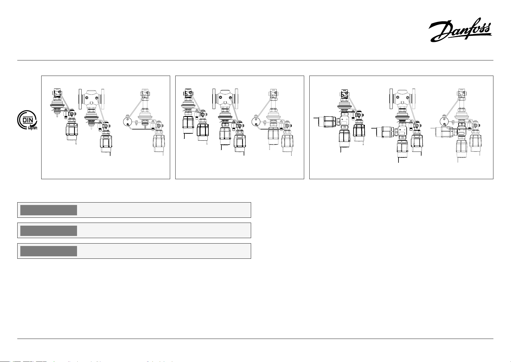
Application examples
Safety temperature limiter
(actuator) STL can be
combined with:
• VG(F) and VGS valves
• AVT actuator and valves
mentioned above
• Combination piece K2,
AVT actuators and valves
mentioned above
Anwendungsbeispiele
Der Schutz-TemperaturBegrenzer (Antrieb) Typ STL
kann kombiniert werden mit:
• Ventilen VG(F) und VGS
• Thermostat AVT und den
oben genannten Ventilen
• Kombinationsstück
K2, zwei Thermostaten
AVT und den oben
genanntenVentilen.
Przykłady zastosowań
Bezpiecznik temperatury
(siłownik) STL można
połączyć z:
• Zaworami VG(F) i VGS
• Siłownikiem AVT
(regulatorem temperatury)
i wymienionymi wyżej
zaworami.
• Łącznikiem
kombinacyjnym K2,
siłownikami AVT i
wymienionymi wyżej
zaworami.
5
ENGLISH DEUTSCH POLSKI
STLV, STLS
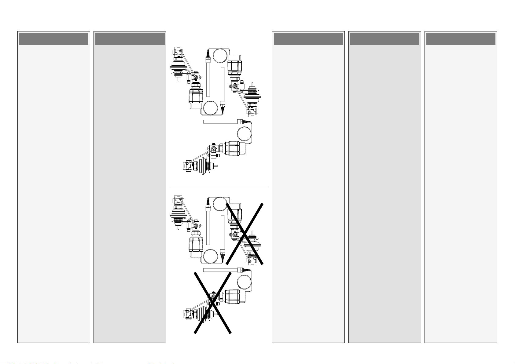
Assembly
Admissible Installation
Positions
• Safety temperature limiter
(actuator) with valves
VG(F) and VGS
Medium temperatures up
to 100 °C:
- Can be installed in any
position.
Medium temperatures
> 100 °C:
- Installation permitted
only in horizontal
pipelines with the
actuator oriented
downwards.
Montage
Zulässige Einbaulagen
• Schutz-TemperaturBegrenzer (Antrieb) Typ
STL mit den Ventilen VG(F)
und VGS
Mediumstemperatur bis
100 °C:
- kann in jeder Lage
eingebaut werden.
Mediumstemperatur
> 100 °C:
- Einbau nur in
waagerechten
Rohrleitungen mit nach
unten hängendem
Antrieb zulässig.
Montaż
Dopuszczalne pozycje
montażu
- Bezpiecznik temperatury
(siłownik) STL z zaworami
VG(F) i VGS.
Temperatura czynnika do
100°C:
- można montować w
dowolnej pozycji.
Temperatura czynnika
>100°C:
- można montować
tylko na rurociągu
poziomym z siłownikiem
skierowanym w dół.
6

ENGLISH DEUTSCH POLSKI
STLV, STLS
• Temperature sensor
The capillary tube may not
be twisted or buckled. The
minimum bending radius
is 50 mm.
The place of installation
must be chosen in a way
that the temperature of
the medium is directly
taken without any delay.
Avoid overheating of
temperature sensor.
The temperature sensor
must be immersed into
the medium in its full
length.
The temperature sensor
may be installed in any
position.
• Temperaturfühler
Das Verbindungsrohr
darf weder verdreht noch
geknickt werden. Der
minimale Biegeradius
beträgt 50 mm.
Der Einbauort ist
so zu wählen, dass
die Temperatur des
Mediums direkt ohne
Verzögerung erfasst wird.
Eine Überhitzung des
Temperaturfühlers ist zu
vermeiden.
Der Temperaturfühler
muss in voller Länge in das
Medium eintauchen.
Die Einbaulage des
Temperaturfühlers ist
beliebig.
• Czujnik temperatury
Rurka kapilarna nie
może być skręcona ani
wybrzuszona (załamana).
Minimalny promień gięcia
wynosi 50 mm.
Miejsce montażu musi
być tak dobrane, aby
temperatura czynnika
była odbierana
natychmiastowo, bez
żadnej zwłoki. Unikać
przegrzewania czujnika
temperatury.
Czujnik temperatury musi
być zanurzony w czynniku
na całej swojej długości.
Czujnik temperatury
można montować w
dowolnej pozycji.
7

ENGLISH DEUTSCH POLSKI
STLV, STLS
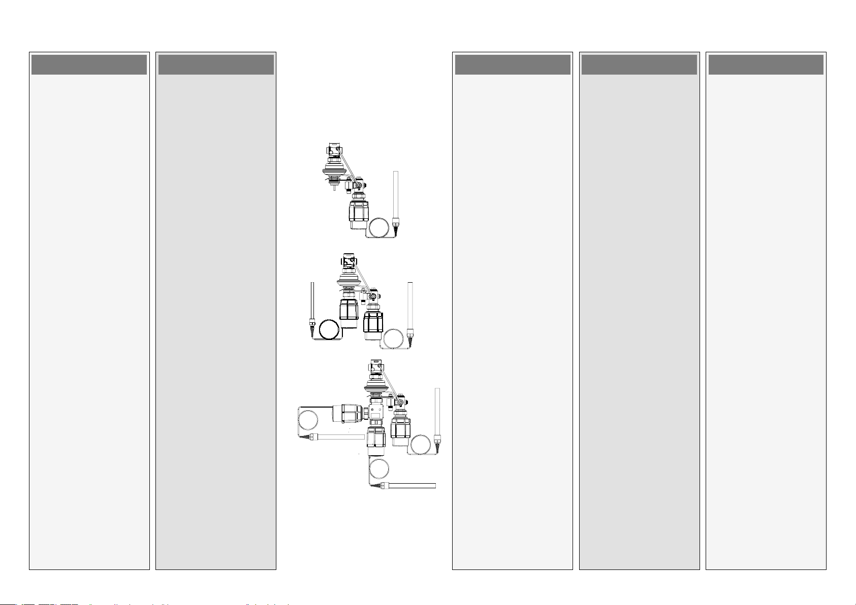
Installation Location and
Installation Scheme
STLV
(STL with valve VG(F))
STLS
(STL with valve VGS)
STLV / AVT
STLV / AVT / AVT
Einbauort und
Einbauschema
STLV
(STL mit Ventil VG(F))
STLS
(STL mit Ventil VGS)
STLV / AVT
STLV / AVT / AVT
Miejsce i schemat montażu
STLV
(STL z zaworem VG(F))
STLS
(STL z zaworem VGS)
STLV / AVT
STLV / AVT / AVT
8

L
ENGLISH DEUTSCH POLSKI
STLV, STLS
Valve Installation
1. Clean pipeline system
prior to assembly.
2. Install a strainer in front of
the controller .
Max. mesh width
DN 15 - 25: 0.5 mm
DN 32 - 50: 0.8 mm
3. Install temperature
indicators in the system
part to be controlled.
4. Install valve
• The flow direction
indicated on the product
label or on the valve
must be observed.
• The valve with mounted
weld-on tailpieces may
only be spot welded to the
pipeline .
The weld-on tailpieces
may be welded only
without the valve and
seals!
If these instructions
are not observed, high
welding temperatures may
destroy the seals.
Einbau des Ventils
1. Vor der Montage ist das
Rohrsystem zu reinigen.
2. Vor dem Regler ist
ein Schmutzfänger
einzubauen.
Max. Maschenweite
DN 15 - 25: 0,5 mm
DN 32 - 50: 0,8 mm
3. In den zu überwachenden
Anlagenbereich ist eine
Temperaturanzeige
einzubauen.
4. Ventil einbauen:
• Die Durchflussrichtung
auf dem Typenschild
oder dem Ventil muss
beachtet werden.
• Das Ventil mit
angeschraubten
Anschweißenden darf
in der Rohrleitung nur
angeheftet werden .
Das Einschweißen der
Anschweißenden ist
nur ohne Ventil und
Dichtungen zulässig!
Bei Nichtbeachtung
zerstören die hohen
Schweißtemperaturen die
Dichtungen des Ventils.
DN L (mm)
15 69
20 74
25 79
32 104
40 114
50 134
Montaż zaworu
1. Przed zamontowaniem
zaworu przepłukać
instalację.
2. Przed regulatorem
zamontować filtr .
Maksymalna wielkość
oczek siatki
DN 15 – 25: 0,5 mm
DN 32 – 50: 0,8 mm.
3. Zamontować wskaźniki
temperatury (termometr)
w tej części układu, która
będzie regulowana.
4. Zamontować zawór.
• Należy zachować kierunek
przepływu zaznaczony na
tabliczce znamionowej
lub na korpusie zaworu .
• Zawór z zamocowanymi
końcówkami do
przyspawania może
być tylko punktowo
przyspawany do rurociągu
.
Końcówki mogą być
przyspawane tylko bez
zaworu i uszczelnienia!
Niezastosowanie się do
tego zalecenia może
spowodować uszkodzenie
uszczelnień wskutek
wysokiej temperatury.
9

ENGLISH DEUTSCH POLSKI
STLV, STLS
• Flanges in the pipeline
must be in parallel
position and sealing
surfaces must be clean
and without any damage.
Tighten screws in flanges
crosswise in 3 steps up
to the maximum torque
(50 Nm).
5. Caution:
Mechanical loads of
the valve body by
the pipelines are not
permitted.
Mounting of safety
temperature limiter
(actuator)
Before mounting the
safety temperature limiter
(actuator), carry out Filling
the system, First start-up and
Leak and pressure tests, see
page 15.
Place safety temperature
limiter (actuator) at the
valve and tighten union
nut with wrench SW 50.
Torque 35 Nm.
• Flansche in der
Rohrleitung müssen
parallel liegen und deren
Oberfläche muss sauber
und unbeschädigt sein.
Schrauben über Kreuz
in drei Schritten bis zum
maximalen Drehmoment
(50 Nm) anziehen.
5. Vorsicht:
Mechanische Belastungen
des Ventilgehäuses durch
die Rohrleitungen sind
nicht zulässig.
Montage des SchutzTemperatur-Begrenzers
(Antrieb)
Vor der Montage des SchutzTemperatur-Begrenzers
(Antriebs), führen Sie
die in den Abschnitten
„Befüllen der Anlage“,
„Erste Inbetriebnahme“
und „Dichtigkeitsprüfung
/ Druckprüfung“
beschriebenen Schritte durch
(siehe Seite 14/15).
Schrauben Sie den SchutzTemperatur-Begrenzer
(Antrieb) auf das Ventil
j und ziehen Sie die
Überwurfmutter mit einem
Schlüssel SW 50 fest.
• Kołnierze na rurociągu
muszą być równoległe
a powierzchnie pod
uszczelki czyste i bez
uszkodzeń.
Dokręcać śruby przy
kołnierzach po przekątnej,
w trzech krokach, aż do
uzyskania maksymalnego
momentu.
5. Uwaga:
Nie można dopuścić do
powstania mechanicznych
obciążeń korpusu zaworu
od rurociągów.
Montaż bezpiecznika
temperatury (siłownika)
Przed zamontowaniem
bezpiecznika temperatury
(siłownika) należy
przeprowadzić napełnienie
i rozruch układu oraz próby
szczelności i ciśnieniowe,
patrz. str. 15.
Zamontuj bezpiecznik
temperatury (siłownik)
na zaworze i dokręcić
nakrętkę łączącą kluczem
SW 50.
Moment 35 Nm.
Drehmoment 35 Nm.
10

ENGLISH DEUTSCH POLSKI
STLV, STLS
Mounting of temperature
actuator
Before mounting the
actuator, carry out Filling the
system, First start-up and
Leak and pressure tests, see
page 15.
Place temperature actuator
at the safety temperature
limiter (actuator) or
combination piece and
tighten union nut with
wrench SW 50.
Torque 35 Nm.
Montage des Thermostats
Vor der Montage des
Antriebs, führen Sie
die in den Abschnitten
„Befüllen der Anlage“,
„Erste Inbetriebnahme“
und „Dichtigkeitsprüfung
/ Druckprüfung“
beschriebenen Schritte durch
(siehe Seite 14/15).
Schrauben Sie den SchutzTemperatur-Begrenzer
(Antrieb) auf das Ventil
und ziehen Sie die
Überwurfmutter mit einem
Schlüssel SW 50 fest.
Drehmoment 35 Nm.
Montaż siłownika
termicznego
(regulacyjnego)
Przed zamontowaniem
siłownika należy
przeprowadzić napełnienie
i rozruch układu oraz próby
szczelności i ciśnieniowe,
patrz. str. 15.
Zamontuj siłownik
termiczny na bezpieczniku
temperatury lub łączniku
kombinacyjnym i dokręcić
nakrętkę łączącą kluczem
SW 50.
Moment 35 Nm.
11

ENGLISH DEUTSCH POLSKI
STLV, STLS
Insulation
Do not insulate the safety
temperature limiter
(actuator), temperature
actuator and the valve as well.
Dimensions, Weights
1)
Conical ext. thread acc. to
EN 10226-1
2)
Flanges PN 25, acc. to
EN 1092-2
Isolierung
Bitte den Schutz-TemperaturBegrenzer (Antrieb), den
Temperaturantrieb und das
Ventil nicht isolieren!
Abmessungen, Gewicht
1)
Kegeliges Außengewinde
nach EN 10226-1
2)
Flansche PN 25 nach EN
1092-2
Izolacja
Nie izolować bezpiecznika
termicznego (siłownika),
siłownika termicznego ani
zaworu.
Wymiary, ciężar
1)
Gwint stożkowy
zewnętrzny wg
EN 10226-1
2)
Kołnierze PN 25 wg
EN 1092-2
DN 15 20 25 32 40 50
SW
d 21 26 33 42 47 60
1)
R
2)
L1
L2 131 144 160 177 - L3 139 154 159 184 204 234
k 65 75 85 100 110 125
d
2
n 4 4 4 4 4 4
32 (G ¾A) 41 (G 1A) 50 (G 1¼A) 63 (G 1¾A) 70 (G 2A) 82 (G 2½A)
½ ¾ 1 1 ¼ - -
mm
130 150 160 - - -
14 14 14 18 18 18
12

DEUTSCH POLSKI
STLV, STLS
STLV
DN 15 20 25 32 40 50
Lx
Ly - - - 180 200 230
H 180 180 180 - - H1 - - - 221 221 221
H2 34 34 37 - - H3 - - - 70 75 82
Note: other flange dimensions - see table for tailpieces
Anmerkung: Weitere Flanschmaße – siehe Tabelle mit Anschlussteilen
Uwaga: Pozostałe w ymiary kołnierzy – patrz tabela z końcówkami
192 192 192 - - -
mm
STLS
DN 15 20 25
Lx
H 405 405 405
H2 34 34 37
290 290 290
mm
13

ENGLISH DEUTSCH POLSKI
STLV, STLS
Start-up
Note
Valves VG(F) and VGS are
normally opened (NO) valves.
Filling the system and Leak
and pressure test should be
done without mounted safety
temperature limiter (actuator)
and temperature actuator
– valve has to be open.
Filling the system, first
start-up
1. Slowly open shut-off
devices in the flow
pipeline.
2. Slowly open shut-off
devices in the return
pipeline.
Inbetriebnahme
Anmerkung
Die Ventile VG(F) und VGS sind
ohne Antrieb / Thermostat
geöffnet.
Das Befüllen der Anlage und
die Dichtigkeitsprüfung bzw.
Druckprüfung muss erfolgen,
ohne dass der SchutzTemperatur-Begrenzer
(Antrieb) und der Thermostat
montiert sind. Das Ventil
muss geöffnet sein.
Befüllen der Anlage, erste
Inbetriebnahme
1. Öffnen Sie langsam die
Absperrarmaturen im
Vorlauf.
2. Öffnen Sie langsam die
Absperrarmaturen im
Rücklauf.
VG(F), VGS
Uruchomienie
Uwaga
Zawory VG(F) i VGS są
zaworami normalnie
otwartymi (NO).
Napełnienie układu oraz
próby szczelności i ciśnienia
układu należy przeprowadzić
bez zamontowanego
termostatu bezpieczeństwa
i siłownika termicznego
– zawór musi być otwarty.
Napełnienie układu,
pierwsze uruchomienie
1. Powoli otworzyć zawory
odcinające na rurociągu
zasilającym.
2. Powoli otworzyć zawory
odcinające na rurociągu
powrotnym.
14

ENGLISH DEUTSCH POLSKI
STLV, STLS
Leak and Pressure Tests
Pressure must
be gradually
increased at the
+/- side of the
valve.
Do not test with closed valve!
Non-compliance may cause
damages at the actuator or
the valve.
A pressure test of the entire
system must be carried
out in accordance with
manufacturer’s instructions.
The maximum test pressure
for the valves is:
1.5 × PN
PN - see product label
Dichtigkeitsprüfung /
Druckprüfung
Der Druck muss
auf der +/- Seite
des Ventils
kontinuierlich
erhöht werden.
Nicht mit geschlossenem
Ventil prüfen!
Bei Nichtbeachtung können
am Antrieb oder Ventil
Schäden entstehen.
Eine eventuell für
die Gesamtanlage
erforderliche Druckprüfung
ist nach
des Anlagenherstellers
vorzunehmen.
Der maximale Testdruck für
die Ventile beträgt
1,5 × PN
PN – siehe Typenschild
den Vorgaben
Próby szczelności i
ciśnienia
Ciśnienie po
stronie +/zaworu należy
zwiększać
stopniowo.
Nie dokonywać próby przy
zamkniętym zaworze!
Niezastosowanie się
do powyższego może
spowodować uszkodzenie
siłownika lub zaworu.
Próba ciśnienia dla
całego układu musi być
przeprowadzona zgodnie
z instrukcją producenta lub
projektanta.
Maksymalne ciśnienie próbne
dla zaworów wynosi:
1.5 x PN
Ciśnienie nominalne
PN podano na tabliczce
znamionowej urządzenia
Putting out of operation
1. Slowly close shut-off
devices in the flow
pipeline.
2. Slowly close shut-off
devices in the return
pipeline.
Außerbetriebnahme
1. Schließen Sie langsam die
Absperrarmaturen im
Vorlauf.
2. Schließen Sie langsam die
Absperrarmaturen im
Rücklauf.
Odłączenie zaworu
1. Powoli zamknąć armaturę
odcinającą na rurociągu
zasilającym.
2. Powoli zamknąć armaturę
odcinającą na rurociągu
powrotnym.
15

ENGLISH DEUTSCH POLSKI
STLV, STLS
Settings
Temperature Setting
The temperature setting
range is indicated on product
label .
Pre-conditions
The system must be opened
and the flow of the medium
guaranteed.
Procedure:
• Set desired setpoint by
turning the handle for
limit setting .
You may only adjust within
the marked range, see .
Turning to the left
(counter-clockwise)
increases the setpoint.
Turning to the right
(clockwise) reduces the
setpoint.
• Observe temperature
indicator .
• Wait for about 3 to 5 min.
until the temperature
indicator shows the final
value.
• If the device is used as a
temperature limiter, the
handle for limit setting
must be sealed by a
sealing wire .
Einstellungen
Temperatureinstellung
Der Sollwertbereich ist
auf dem Typenschild
angegeben.
Voraussetzungen
Die Anlage muss geöffnet
und der Durchfluss des
Mediums muss sichergestellt
sein.
Vorgehensweise:
• Stellen Sie den
gewünschten Sollwert
durch Drehen des
Handgriffs für die
Grenzwerteinstellung
ein.
Sie können nur einen Wert
innerhalb des markierten
Bereichs wählen.
Eine Linksdrehung (gegen
den Uhrzeigersinn) erhöht
= vergrößert den Sollwert.
Eine Rechtsdrehung (im
Uhrzeigersinn) verringert
= verkleinert den Sollwert.
• Beobachten Sie die
Temperaturanzeige .
• Warten Sie 3 bis 5 Minuten,
bis die Temperaturanzeige
den Endwert anzeigt.
• Der Handgriff für die
Grenzwerteinstellung
kann mit Plombierdraht
gesichert werden.
Nastawy
Nastawa temperatury
Zakres nastawy temperatury
podano na tabliczce
znamionowej .
Warunki wstępne
Układ musi pracować w
trakcie zadawania nastawy.
Tok postępowania:
• Dokonać ustawienia
obracając pokrętłem
nastawczym .
Można dokonywać
nastawy tylko w
zaznaczonym zakresie,
patrz .
Obracanie w lewo
(przeciwnie do ruchu
wskazówek zegara)
zwiększa wartość nastawy.
Obracanie w prawo
(zgodnie z ruchem
wskazówek zegara)
zmniejsza wartość
nastawy.
•
Obserwować wskaźnik
temperatury (termometr) .
• Odczekać około 3 do
5 min. aż wskaźnik
temperatury pokaże
ostateczną wartość.
• Jeżeli urządzenie ma
służyć jako termostat
bezpieczeństwa, wówczas
pokrętło nastawcze
należy zaplombować .
16

ENGLISH DEUTSCH POLSKI
STLV, STLS
Temperature setting
– AVT
(relevant only at STLV/AVT
(/AVT), STLS/AVT (/AVT)
controllers)
See instructions for
temperature actuator AVT.
Resetting of safety
temperature limiter
1 Valve
2 Pressure a ctuator
3 Impuls e tube
4 Regula ting valve
5 Releas ing screw
6 Safet y thermostat
7 Temperatu re actuator AVT
8 Handle f or limit setti ng, prepared fo r
sealin g
9 Handle f or temperature s etting,
prepar ed for sealing
10 Temperatu re sensor
11 Capill ary tube of the sa fety thermo stat
12 Capill ary tube of temp erature regul ator
In case the temperature at the
temperature sensor (pos. 10)
exceeds the adjusted set
point, safety thermostat
(6) moves thermostat stem
out and opens regulating
valve (4). The pressure of the
medium before the valve (1) is
being transferred to the lower
chamber of pressure actuator
(2) and closes the valve (1).
Temperatureinstellung
– AVT
(gilt nur für Regler des Typs
STLV/AVT (/AVT), STLS/AVT
(/AVT))
Siehe Anweisungen für den
Thermostat AVT.
Zurücksetzen des SchutzTemperatur-Begrenzers
1 Ventil
2 Drucka ntrieb
3 Steuerl eitung
4 Regel ventil
5 Entrieg elungsschrau be
6 Sicherh eitsthermo stat
7 Thermo stat AVT
8 Handgr iff für die Einstel lung des
Grenz werts, mit Plo mbierbohru ng
9 Handgr iff für die Temperatu reinstellung ,
mit Plomb ierbohrung
10 Temperatu rfühler
11 Verbindu ngsrohr des
Sicherh eitsthermo stats
12 Verbindu ngsrohr des The rmostaten
Wenn die Temperatur am
Temperaturfühler (10)
den eingestellten Sollwert
übersteigt, fährt der
Sicherheitsthermostat (6)
die Antriebsstange aus und
öffnet das Regelventil (4). Der
Druck des Mediums vor dem
Ventil (1) wird in die untere
Druckkammer des Antriebs
(2) übertragen und das
Stellventil(1) geschlossen.
Nastawa temperatury
– AVT.
(tylko dla regulatorów
STLV/AVT(/AVT) i STLS/AVT(/AVT).
Patrz instrukcje dla siłownika
termicznego (regulacyjnego)
AVT.
Resetowanie
(po zadziałaniu)
bezpiecznika temperatury.
1 Zawór
2 Siłowni k membranow y (ciśnieniow y)
3 Rurka im pulsowa
4 Zawór ste rujący
5 Śruba do o dblokowy wania
6 Termostat b ezpieczeń stwa
7 Siłowni k termiczny (ter mostat) AVT
8 Nastaw nik temperatur y bezpiec zeństwa
z otwore m na plombę.
9 Nastaw nik temperatur y termostatu
reguluj ącego z otwore m na plombę
10 Czujni k temperatur y
11 Kapila ra termostatu b ezpieczeń stwa
12 Kapila ra termostatu r egulującego
W przypadku przekroczenia
na czujniku (10) nastawionej
temperatury bezpieczeństwa,
termostat bezpieczeństwa
(6) powoduje wysunięcie
trzpienia termostatu i
otwarcie zaworu sterującego
(4). Ciśnienie czynnika
sprzed zaworu (1) zostaje
doprowadzone do dolnej
komory siłownika (2) i powoduje
zamknięcie zaworu (1).
17

ENGLISH DEUTSCH POLSKI
STLV, STLS
The valve remains closed:
- until the temperature,
at the temperature
sensor, decreases below
the adjusted set point
- regulating valve closes.
- manual reset is done
Before manual resetting
pressure actuator has to be
cooled down. Medium in it
might be hot.
Manual reset is done by
opening of a releasing screw
(pos. 5) - medium from
pressure actuator is being
transferred out.
Safety function
Das Ventil bleibt geschlossen,
bis:
- die Temperatur am
Temperaturfühler
unter den eingestellten
Sollwert fällt - das
Regelventil wird
geschlossen.
- ein manueller Reset
(an der Entriegelungsschraube)
erfolgt ist.
Vor dem manuellen Reset muss
der Antrieb abkühlen. Das
Medium könnte zu heiß sein.
Ein manueller Reset
erfolgt durch Öffnen der
Entriegelungsschraube
(5) - das Medium aus
dem Druckantrieb wird
abgelassen.
Sicherheitsfunktion
Zawór pozostaje trwale
zamknięty dopóki:
- temperatura na czujniku
temperatury pozostaje
wyższa od nastawionej,
- zawór regulacyjny zamyka
przepływ,
- nie zostanie dokonane
ręczne odblokowanie
(reset).
Przed dokonaniem ręcznego
odblokowania (resetu) musi
zostać schłodzony siłownik
membranowy. Czynnik w
siłowniku może być gorący.
Ręcznego odblokowania
(resetu) dokonuje się
poprzez wykręcenie śruby
odblokowywującej (5) co
spowoduje wypłynięcie
czynnika spod membrany
siłownika.
Funkcja bezpieczeństwa
If there is a leakage in the
area of the temperature
sensor (10) , the capillary tube
(11), or the safety thermostat
(6), the regulating valve (4)
opens. The pressure of the
medium before the valve (1) is
being transferred to the lower
chamber of pressure actuator
(2) and closes the valve (1). In
this case safety temperature
limiter (actuator) must be
replaced.
Wenn im Bereich des
Temperaturfühlers (10), des
Verbindungsrohrs (11) oder
des Sicherheitsthermostats
(6) ein Leck auftritt, öffnet das
Regelventil (4). Der Druck des
Mediums vor dem Stellventil
(1) wird in die untere
Kammer des Druckantriebs
(2) übertragen und das
Stellventil (1) geschlossen. In
diesem Fall muss der SchutzTemperatur-Begrenzer
(Antrieb) ersetzt werden.
Rozszczelnienie w przestrzeni
czujnika temperatury
(10), rurki kapilarnej (11)
lub mieszka termostatu
bezpieczeństwa (6),
spowoduje otwarcie zaworu
sterującego (4). Ciśnienie
czynnika sprzed zaworu (1)
zostanie doprowadzone do
dolnej komory siłownika
(2) i spowoduje zamknięcie
zaworu (1). W takim
przypadku należy wymienić
termostat bezpieczeństwa.
18
 Loading...