

Page 1
MAKING MODERN LIVING POSSIBLE
SpeedUp™ Heating Systems
DANFOSS HEATING SOLUTIONS Handbook
Page 2

Handbook SpeedUp™ Heating Systems
2
VGCTA2302 © Danfoss 09/2009
Page 3
Handbook SpeedUp™ Heating Systems
Index
Page
Introduction SpeedUp™ and SpeedUp Eco™ . . . . . . . . . . . . . . . . . . . . . . . . . . 4
Heating systems. . . . . . . . . . . . . . . . . . . . . . . . . . . . . . . . . . . . 4
System variations . . . . . . . . . . . . . . . . . . . . . . . . . . . . . . . . . . . 4
Advantages. . . . . . . . . . . . . . . . . . . . . . . . . . . . . . . . . . . . . . . 4
Standards and guidelines . . . . . . . . . . . . . . . . . . . . . . . . . . . . . . 5
Minimum thermal resistance of insulation
under floor heating systems from EN 1264, Part 4 . . . . . . . . . . . . . . 5
System parts . . . . . . . . . . . . . . . . . . . . . . . . . . . . . . . . . . . . . . 5
Overview SpeedUp Panels . . . . . . . . . . . . . . . . . . . . . . . . . . . . . . . . . . . . 6
SpeedUp Eco Panels . . . . . . . . . . . . . . . . . . . . . . . . . . . . . . . . . 7
To ol s . . . . . . . . . . . . . . . . . . . . . . . . . . . . . . . . . . . . . . . . . . . 8
Floor Construction Substrate requirements . . . . . . . . . . . . . . . . . . . . . . . . . . . . . . . 9
Tolerance levels for evenness . . . . . . . . . . . . . . . . . . . . . . . . . . . 9
Levelling of sustrate (Danfoss recommends) . . . . . . . . . . . . . . . . . . 9
Separation of pipe from load bearing layer . . . . . . . . . . . . . . . . . . 10
Low surface weight . . . . . . . . . . . . . . . . . . . . . . . . . . . . . . . . . . 10
Level free surface . . . . . . . . . . . . . . . . . . . . . . . . . . . . . . . . . . . 10
Basic construction . . . . . . . . . . . . . . . . . . . . . . . . . . . . . . . . . . 10
Additional insulation . . . . . . . . . . . . . . . . . . . . . . . . . . . . . . . . . 11
Categories of loaded areas . . . . . . . . . . . . . . . . . . . . . . . . . . . . . 12
Insulation values . . . . . . . . . . . . . . . . . . . . . . . . . . . . . . . . . . . 13
Min. thermal resistance of insulating layers (m
2
K)/W
below the floor heating/cooling system . . . . . . . . . . . . . . . . . . . . 13
Sound impact . . . . . . . . . . . . . . . . . . . . . . . . . . . . . . . . . . . . . 14
SpeedUp™ perimeter insulation . . . . . . . . . . . . . . . . . . . . . . . . . . 16
Tanking for wet screed. . . . . . . . . . . . . . . . . . . . . . . . . . . . . . . . 16
Sound impact insulation and wet screed . . . . . . . . . . . . . . . . . . . . 16
Danfoss composite pipes . . . . . . . . . . . . . . . . . . . . . . . . . . . . . . 16
Determine parts Danfoss lay-out pattern . . . . . . . . . . . . . . . . . . . . . . . . . . . . . . . 17
for a system Determine number of SpeedUp™ system parts . . . . . . . . . . . . . . . . 18
Example: Calculation of SpeedUp™. . . . . . . . . . . . . . . . . . . . . . . . 18
Determine number of SpeedUp Eco™ system parts . . . . . . . . . . . . . 19
Example: Calculation of SpeedUp Eco™ . . . . . . . . . . . . . . . . . . . . . 19
Installation Installation . . . . . . . . . . . . . . . . . . . . . . . . . . . . . . . . . . . . . . . 20
Check-list for installation of SpeedUp™ heating system. . . . . . . . . . . 20
Strongboard for tiles, check-list before and during installation . . . . . . 21
Installation time . . . . . . . . . . . . . . . . . . . . . . . . . . . . . . . . . . . . 21
Output tables . . . . . . . . . . . . . . . . . . . . . . . . . . . . . . . . . . . . . . . . . . . . . . . 22
VGCTA302 © Danfoss 09/2009
3
Page 4
Handbook SpeedUp™ Heating Systems
- Introduction
SpeedUp™ and
SpeedUp Eco™
Heating systems
Dry installation and fast reacting wet screed
underfloor heating with low construction height
and weight, and quick response time.
Wherever a low construction floor is required to
save on headroom, or a screed floor is unsuitable,
the SpeedUp™ dry installation is a suitable
alternative. It also suitable for wet screed where
the floor level in heated rooms must stay the
same as in any adjoining unheated room.
SpeedUp™ solves individual heating problems.
The SpeedUp™ underfloor heating systems are
universal and optimum for all new and old
buildings. They are particularly suitable for
retrofitting in restoration work, extensions, and
for use in dry and timber installations.
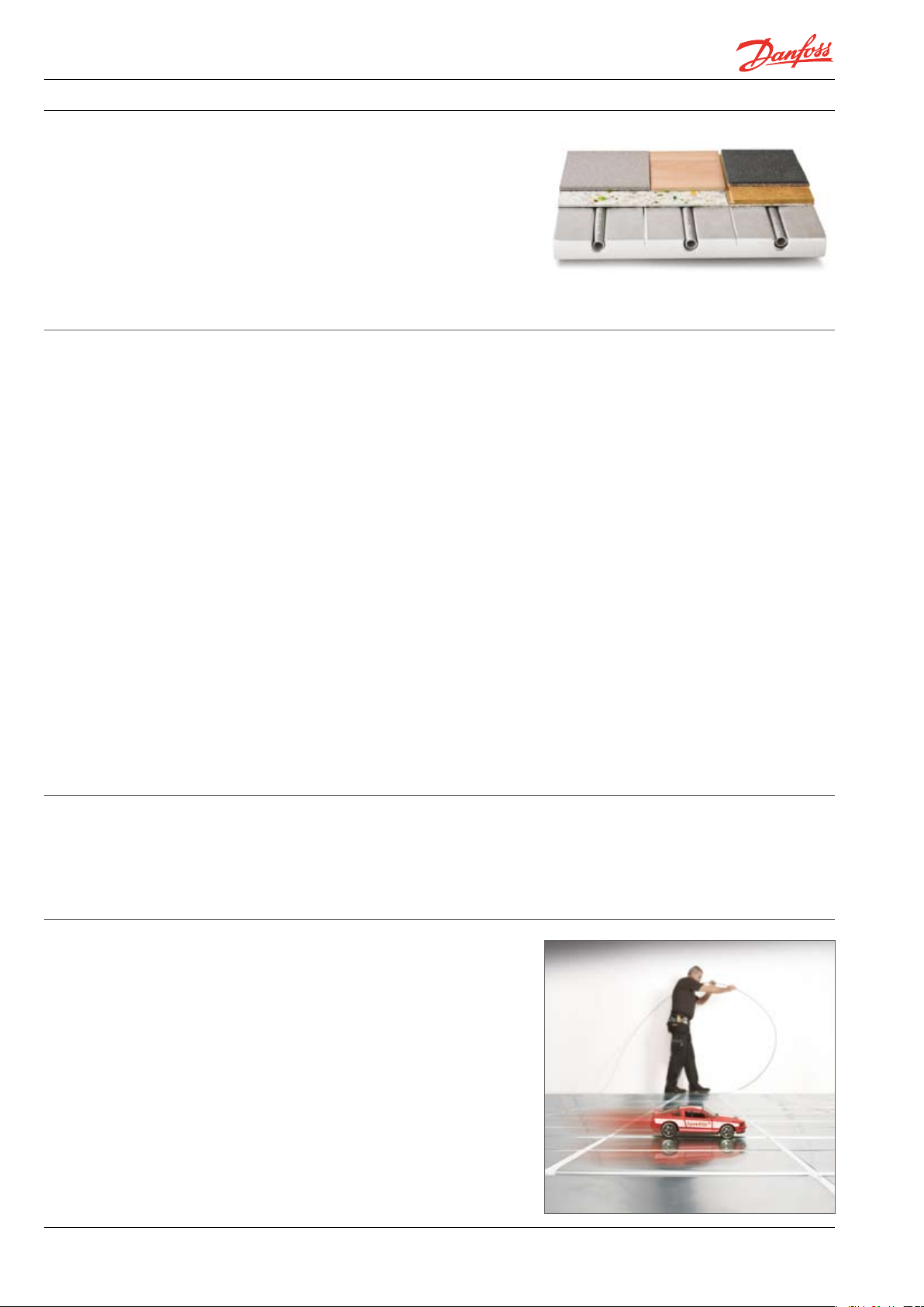
The individual heat panels are only 30 mm thick
and are prefabricated. In contrast to steel
(thermal conductivity 45 W/mK) the aluminium
covering all heat panels is a very good conductor
of heat (thermal conductivity 200 W/mK) so that
the heat is distributed equally and fast over the
entire area.
The pipes are 100% impervious to air so that over
the mid and long term the metal parts of the
heating system cannot suffer from corrosion.
Heat exchangers are not required.
Dry screed (20-25 mm) as well as engineered
flooring and laminates are suitable for load
bearing. Wherever floor height is a problem,
Danfoss Strongboard (5 mm) load bearing panels
offer the opportunity to lay tiles straight onto
SpeedUp™. In contrast to traditional underfloor
heating systems, a very thin layer of liquid screed
can be applied to SpeedUp™, saving mass, weight
and height.
The system is able to react very quickly to
temperature changes and is adjustable like light.
The whole system is available from one source.
Heat output is achieved quickly.
The extremely low flow temperatures are energy
efficient which makes the system ideally suited
for condensing boilers, heat pumps and solar
energy.
Via accessories (mixing shunts, RTB valves) the
system can be connected to existing heating
systems.
System variations
Advantages
4
Depending on the type of installation, system
panels are manufactured from different materials:
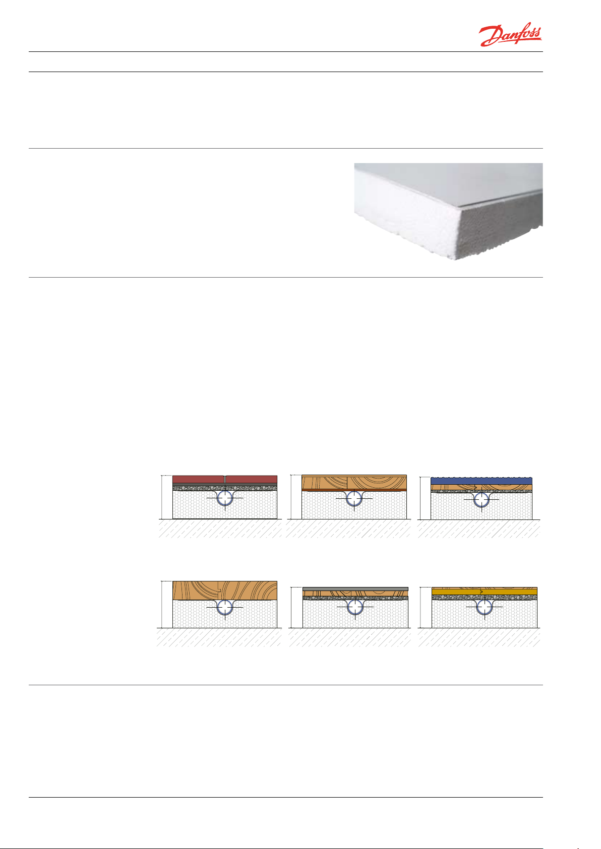
· SpeedUp™ with highly resilient insulation,
EPS 035 DEO 240 kPa.
Fast response time.•
Heat is only emitted when required.•
Prefabricated and easy to install system panels.•
Maintenance free and energy efficient.•
Clean and healthy warm air.•
Fast dry installation without residual moisture.•
VGCTA2302 © Danfoss 09/2009
· SpeedUp Eco™ with ecological wood fibre
insulation 140 kPa, which reduces impact
sound.
Page 5
Handbook SpeedUp™ Heating Systems
- Introduction
Standards and
guidelines
Minimum thermal
resistance of insulation
under floor heating
systems from EN 1264,
part4
System parts
For planning and construction legal requirements
and regulations have to be followed.
For dry underfloor heating EN 1264 is applicable.
Three Danfoss basic constructions are possible
under EN 13813 'Screed in the Building Industry'.
Construction Heated room
Thermal
resistance (R)
(m K/W)
* When ground water table is ≤ 5 m this value should be raised !
The Danfoss SpeedUp™ system parts are made of
compression resistant polystyrene EPS DEO 240
kPa or of wood fibre 140 kPa. The wood fibre load
bearing panels serve as thermal and sound
insulation.
To achieve optimum lateral heat transfer (edge/
outside wall much heat - inner area less heat) the
heat panels have pre-formed pipe channels with
two distances. The edge zone can be covered by
EZ-Panels with pipe distances of 12.5 cm and in
the comfort zone CZ-Panels with pipe distances
of 25cm are installed. Both systems are pre-channelled and are covered with heat conducting
aluminium sheet for optimum heat distribution.
The aluminium pipe channels are omega shaped
so that the pipes easily snap in when installed but
cannot ‘spring’ out afterwards. The channels are
beaded at the ends to avoid damage to the
composite pipe during and after installation.
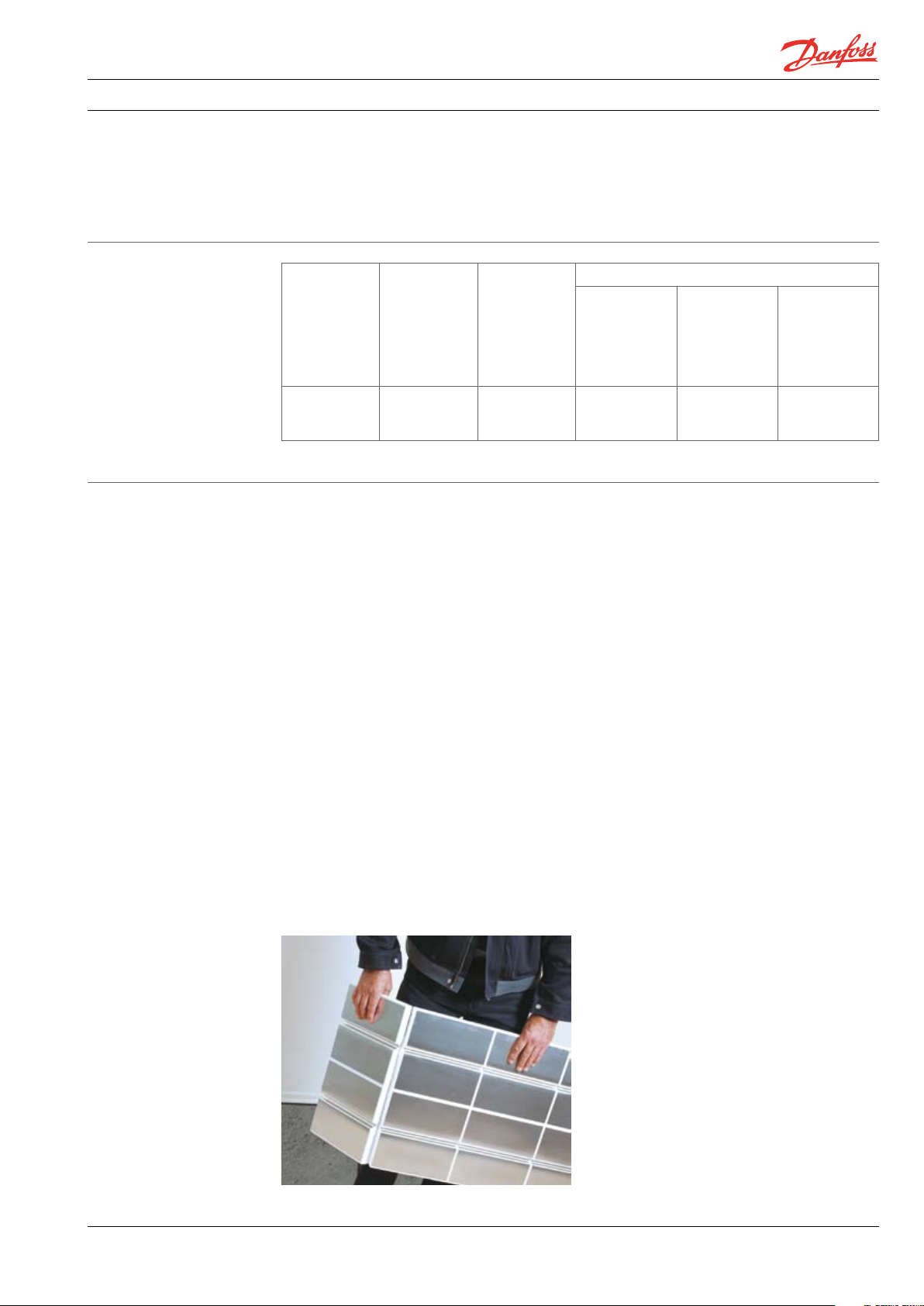
The 1 m long and 0.5 m wide system panels are
pre-scored with the heating plates already cut in
the appropriate places so that the panels can be
snapped over the knee without tools, thus
avoiding unnecessary breaks (this does not apply
to SpeedUp Eco™ panels).
below
0.75 1.2 5 1.2 5 1.5 2
Unheated
room or
occasionally
heated room
below or
room on
ground floor *
They meet the minimum required insulation in
relation to use and position in the home.
For minimum thermal resistance of insulation
under underfloor heating see EN 1264, part 4.
Outside air temperature below construction
Design
outside
temperature
Td > 0° C
This way the system can be adapted to any room
dimensions, even the most awkward corners can
be fully covered.
Together with the two different panel types there
are matching 25 cm header panels, EZ and CZ, to
allow the pipe to return. The header panel CO
allows the cross over between 12.5 cm and 25 cm
pipe distances. Panels for flow and return pipes
CZ and EZ without aluminium plates make it
possible to take supply and returns through
unheated rooms and rooms with low temperature requirement without losing heat. Remaining
areas or areas in front of manifold require blank
panels BP. These are pre-scored as well.
Speedup Eco™ makes up the system with
additional 12.5 cm wide and 1 m long flow and
return panels with routed pipe channels and 90°
curve panels (to allow change of direction in the
flow and return area).
Support battens for stabilisation and sound
insulation as well as load bearing steel sheets
(stabilisation in front of manifold) and heating
aluminium plates (for header panels) complete
the system.
Design
outside
temperature
0° C > Td ≥ -5° C
Design
outside
temperature
-5° C > Td≥ -15°C
VGCTA302 © Danfoss 09/2009
5
Page 6
Handbook SpeedUp™ Heating Systems
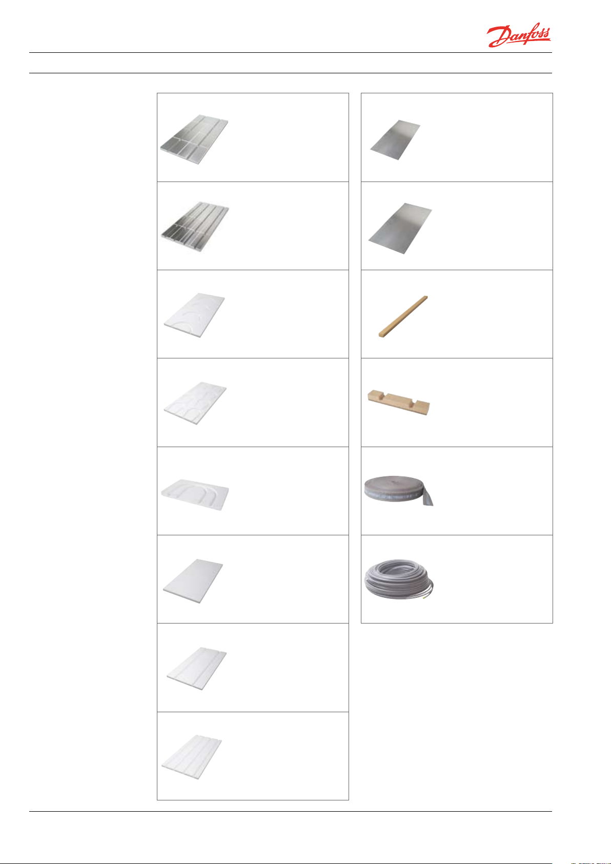
SpeedUp Panels
- Overview
08 8X0100
SpeedUp Heat Panel
Comfort Zone CZ
088X0101
SpeedUp Heat Edge Zone
EZ
08 8X0102
SpeedUp Header Panel
Comfort Zone CZ
08 8X0103
SpeedUp Header Panel
Edge Zone EZ
0 88 X 0110
Heating plate
(aluminium)
0 88 X 0111
Load Bearing Sheet
(Steel)
08 8X013 4
Support Batten
088X0135
Threshold Support Batten
08 8X0104
SpeedUp Header Panel
Cross Over CO
08 8X0105
SpeedUp Blank Panel BP
08 8X0106
SpeedUp Flow and Return
Panel CZ
08 8X0107
SpeedUp Flow and Return
Panel EZ
08 8X0122
Perimeter insulation
088X0001
FH Composite pipe, 200 m,
16 x 2 mm
088X0003
FH Composite pipe, 500 m,
16 x 2 mm
6
VGCTA2302 © Danfoss 09/2009
Page 7
Handbook SpeedUp™ Heating Systems
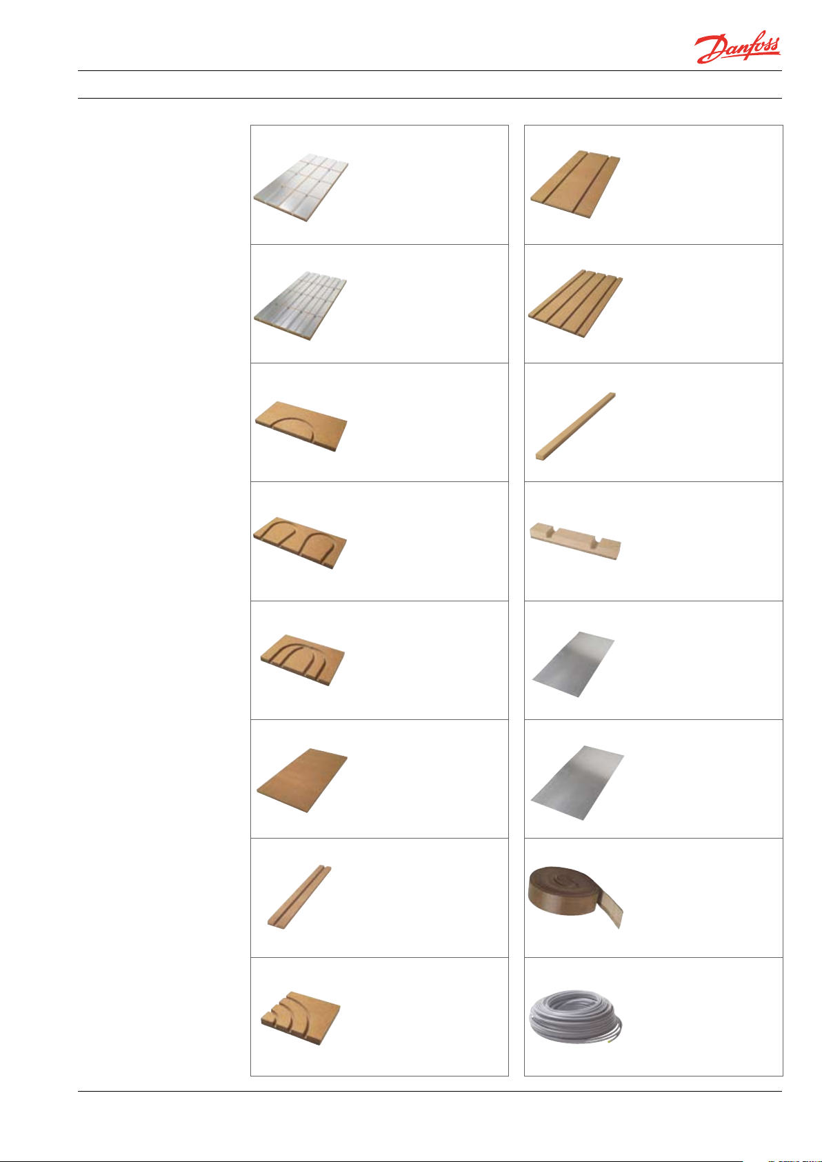
SpeedUp Eco Panels
- Overview
088X0201
SpeedUp Eco Heat Panel
Comfort Zone CZ
088X0202
SpeedUp Eco Heat Panel
Edge Zone EZ
088X0203
SpeedUp Eco Header Panel
Comfort Zone CZ
088X0204
SpeedUp Eco Header Panel
Cross Over CO
088X0209
SpeedUp Eco Flow and
Return Panel CZ
08 8X0210
SpeedUp Eco Flow and
Return Panel EZ
08 8X013 4
Support Batten
088X0135
Threshold Support Batten
088X0205
SpeedUp Eco Header Panel
Edge Zone EZ
088X0206
SpeedUp Eco Blank Panel
BP
088X0207
SpeedUp Eco Flow and
Return Panel
088X0208
SpeedUp Eco 90° Curve
Panel
0 88 X 0110
Heating plate
(aluminium)
0 88 X 0111
Load Bearing Sheet
(Steel)
08 8X0123
Perimeter insulation
088X0001
FH Composite pipe, 200 m,
16 x 2 mm
088X0003
FH Composite pipe, 500 m,
16 x 2 mm
VGCTA302 © Danfoss 09/2009
7
Page 8

Handbook SpeedUp™ Heating Systems
- Overview
Tools
Pipe cutter
The Danfoss pipe cutter, incl. corrugate pipe
cutter for trimming of Danfoss composite pipes
16 x 2.00 mm / 20 x 2.25 mm and the Danfoss
corrugated protective pipe.
Pipe cutter
Danfoss universal pipe cutter for trimming of
Danfoss composite pipes up to 32 x 3 mm and
the Danfoss clip rail BasicRail
Bevelling tool
Danfoss bevelling tool for calibrating and
bevelling the Danfoss Composite Pipes. The
handle is removable so the tool can be attached
to rechargeable drills (< 500 U/min). Dimensions
of 16-20 mm allow inner and outer bevels which
facilitates installation.
Pipe bending springs
The Danfoss pipe bending springs are able to
form radiuses of up to 4 x D. It facilitates
installation and reduces strain on fittings.
Pressing tool
The Danfoss pressing tool is, together with the
inserts, suitable for pressing of Danfoss
composite pipe fittings with dimensions of
16-20 mm.
SpeedUp™ hot wire cutter
The Danfoss hot wire cutter, with its hot blade
and channel cutter, will cut pipe curves, pipe
channels and cleanly cut polystyrene panels.
Pipe dispensing wheel
The Danfoss pipe dispensing wheel is indispensable for one-man installations. It holds up to
200 m of coiled pipe, is compact and easy to
transport and will fit into narrow spaces.
An expansion kit for up to 500 m of coiled pipe
is available.
Ball nose routing bit
The Danfoss ball nose routing bit is used for
milling tracks in the SpeedUp Eco™ blank
panels.
8
VGCTA2302 © Danfoss 09/2009
Page 9
Handbook SpeedUp™ Heating Systems
- Floor Construction
Substrate requirements
Tolerance levels
for evenness
Levelling of substrate
(Danfoss recommends)
The following reqirements have to be met when
installing Danfoss SpeedUp™ heating systems:
The substrate must be dry and firm, it must be
Group Reference 0.1 m 1 m 4 m 10 m 15 m
Finished floors but subject to more stringent
4
requirements. e.g. self-levelling fillers
The system panels must lie fully flat on the
surface since load bearing steel plates in dry
installations cannot compensate for unevenness.
If the prerequisites are not met, levelling and
adjustments have to be undertaken dependent
on the deviation and surface (see table).
Correct minor
unevenness with
levelling products
typically from
builders merchants.Up to 10
mm levelling (e.g.
Maxit Floor 4010).
Up to 20 mm filler
(e.g. Maxit 4160 ).
Prime unfinished
floor (e.g.
Maxitfloor 4716).
For unevenness
over 20 mm use
levelling screed
(Maxit 446) , dry
compound if
moisture and
weight are not
important factors.
Prime unfinished
floor(e.g.
Maxitfloor 4716).
Level service
channels up to 50
mm level with
composite screed.
Depressions and
built-up height
over 30 mm are
levelled with dry
screed composite
panel Fermacell
2E31 (20 mm
gypsum fibre
board plus 10 mm
wood fibre
insulation).
Level minor
unevenness first.
rigid and free from cracks, as well as free from
cleaning agents and dirt.
Maximum deviation in mm, over distance in m
1 mm 3 mm 9 mm 12 mm 15 mm
Greater installation height with unevenness or
many pipe channels may require levelling and
build up of extra height with screed on insulation. The screed will achieve the necessary
evenness and will make further measures
unneccessary. It is also possible to add further
height using commercial insulation material.
Cover dry
levelling compound between
10-50 mm for
small objects with
load bearing
panel (10 mm
gypsum fibre).
Cover service
channels over 3
cm and construction over 11 cm
with screed on
insulation.
Unevenness of up to 3 mm is not a problem. Thin
wood fibre insulation or moisture barriers (e.g.
Gefitas/Firma Gefinex) eliminate this problem.
Unevenness of up to 10 mm can be eliminated
with self-leveling compound. Greater height
differences can be overcome with bonded dry
levelling compound (e.g. Danfoss dry levelling
compound). Before installing the compound on
the suspended floor the prepared area should be
lined to protect against any compound falling
through. As a rule the thickness of the levelling
compound is between a minimum of 10 mm and
a maximum of 60 mm. It is advisable to read the
manufacturer information. A finishing board is
used to make the compound safe to walk on. The
use of additional insulation with Danfoss dry
levelling compound makes the installation of the
board unnecessary. The additional insulation can
be installed directly on the leveling compound. It
is always advisable to follow the manufacturer
information when installing dry screed panels If
there is residual moisture in the building, a 0.2
mm PE foil will prevent the rising of the moisture
VGCTA302 © Danfoss 09/2009
into the building. Length of foil overlap by 20 cm,
at the edge up to floor level. Floors between
storeys don’t need a moisture seal since there is
no residual moisture. Suspended floors should
not have any lining since moisture could be
trapped and cause lasting damage. In accordance
with EN 13967 constructions on ground floors
must be protected against any moisture entering
the floor. In the absence of a lining, bitumen or
synthetic lining can be used; the floor will need
levelling afterwards. Such measures may have to
be decided by the builder.
For floors with greater exposure to humidity e.g.
bathrooms or entrance halls, dry screed panels
such as Fermacell will need a thick coating or a
sealing system before tiling. For shower rooms
and washrooms with floor drains in public and
commercial premises, Fermacell screed panels
are not suitable.
For wet areas, Fermacell Powerpanel SE can serve
as an alternative.
9
Page 10
Handbook SpeedUp™ Heating Systems
46
47
47
50
45
43
- Floor Construction
Separation of pipe from
load bearing layer
Low surface weight
Level free surface
SpeedUp™ is the Danfoss underfloor heating
system, where pipes are integrated into the
system panels and decoupled from the load
bearing layer.
The relatively light weight of dry screed makes
the whole construction light weight, which is an
advantage as well as essential in restoration of
older buildings, where floors are of lower load
bearing construction.
Danfoss Strongboards provide a unique solution
for level free floors.
With a thickness of only 5 mm the Strongboard
for Tiles and Laminates provides sufficient
stability as a load bearing layer to comply with
the demands of EN 1991 (Actions of structures).
The Strongboard for Carpet and Synthetics
provides the same stability, but with a thickness
of 10 mm.
Danfoss Strongboards are made of recycled
materials mixed with shreds of aluminium, which
ensure good heat transfer through the Strongboard to floor finish.
This means that the joints of the load bearing
panels do not have to be taken into consideration
when planning the heating circuit.
Where Strongboard for Tiles and Laminates does
not have a completely smooth surface, the
Strongboard for Carpet and Synthetics can serve
as a smooth surface for floor finishes like carpet,
linoleum, vinyl etc. A smooth surface can
therefore be achieved with only 10 mm instead of
the 20 mm or more that dry or wet screed
requires.
Danfoss Strongboards can be used as a replacement for the Fermacell 20 mm or 25 mm panels.
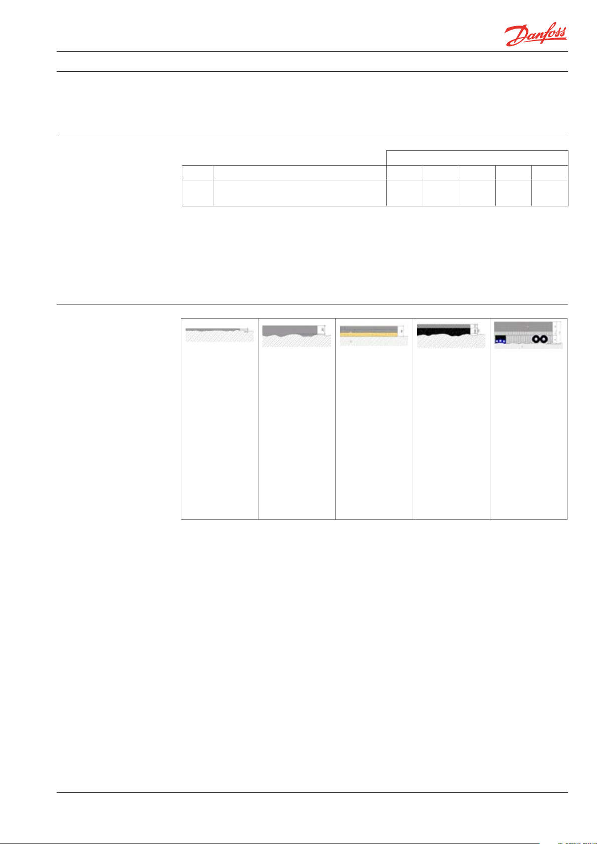
Basic construction
Danfoss Strongboards gives you the possibility to have almost level free floor surfaces
- no matter which floor finish you choose.
Strongboard for tiles and
laminates w/ tiles
Direct flooring
w/ wooden planks
Because of their constituent material and
construction, Strongboard, 20-35 mm dry screed
panels, engineered timber or laminates are used
in homes. For higher active loads the dry screed
Direct flooring
w/parquet
Strongboard for carpet and
synthetics w/ e.g. vinyl
in the house) extruded rigid foam and expanded
Polystyrene (200 kPa density) can be used.
If necessary, the load bearing panels have to be
reinforced (see table on page 11).
Strongboard for carpet and
synthetics w/ carpet
Strongboard for tiles and
laminates w/ laminate
is reinforced.
As an additional insulation under the heating
panels (thickness depending on use and position
10
VGCTA2302 © Danfoss 09/2009
Page 11

Handbook SpeedUp™ Heating Systems
- Floor Construction
Additional insulation
Maximum layers (number)
and thickness of insulation
SpeedUp™ Heating System
Applications Areas for domestic and residential activities (e.g. rooms in residential
Load bearing surface
Thickness (mm) 5 10 8 / 5 15 20 -22 20 25
EPS DEO 200 kPa WLG 035 (mm) max. 20 max. 20 max. 20 max. 20 max. 40 max. 50 max. 70
Maximum layers (pcs.) 1 1 1 1 1 1 2
XPS DEO 300 kPa WLG 035 (mm) max. 30 max. 30 max. 30 max. 30 max. 40 max. 50 max. 70
Maximum layers (pcs.) 1 1 1 1 1 2 2
XPS DEO 500 kPa WLG 035 (mm) max. 60 max. 60 max. 60 max. 60 max. 60 max. 70 max. 90
Maximum layers (pcs.) 1 1 1 1 2 1 2
Wood fibre insulation 150 kPa (mm) - max. 20 max. 20 max. 20 max. 20 - max. 40
Maximum layers + 12.5 mm
filler panel under SpeedUp (pcs.)
Levelling with Danfoss dry levelling
compound
* Point load: area at least 20 cm
aquariums, baths.
buildings and houses; bedrooms and wards in hospitals; bedrooms in hotels
and hostels; kitchens and toilets), office areas.
Point load: 2.0 KN*; Actual load: 2.0 kN/m
laminates
for tiles and
Strongboard
Not
possible
2
, maximum distor tion ≤ 3 mm; allowances to be made for particularly heavy items, e.g.
carpet
Strongboard
1 (essential) 1 1
+ 12.5 mm load bearing panel
Additional insulation > 30 mm or dry levelling compound >30 mm:
Reduce the maximum permitted additional insulation by the level
of the dry compound
Laminate
Engineered
timber floor
on battens
Solid timber
Fermacell
Fermacell
SpeedUp Eco™ Heating System
Applications Areas for domestic and residential activities (e.g. rooms in residential
Load bearing surface
Thickness (mm) 5 10 8 / 5 15 20-2 2 20 25
Wood fibre insulation 150 kPa (mm) max. 20 max. 20 max. 20 max. 20 max. 40 max. 20
Maximum layers
plus OSB-load bearing surface
under SpeedUp
Wood Fibre > 150 kPA (mm)
Pavatex Pavaboard 150 kPa
Gutex Thermowall - gf 200 kPa
Glunz Agepan THD 230
Maximum layers
plus OSB-load bearing surface
under SpeedUp
Levelling with
Danfoss dry levelling compound
* Point load: Load area min. 20 cm
aquariums, baths.
buildings and houses; bedrooms and wards in hospitals; bedrooms in hotels
and hostels; kitchens and toilets), office areas.
Point load: 2.0 KN*; Actual load: 2.0 kN/m
laminates
for tiles and
Strongboard
1
22 mm115 mm115 mm115 mm
max. 20 max. 20 max. 40 max. 40 max. 40 max. 20
1
22 mm118 mm118 mm115 mm
Not
possible
2
, maximum distor tion ≤ 3 mm; allowances to be made for particularly heavy items e.g.
carpet
Strongboard
Additional insulation > 30 mm or dry levelling compound > 30 mm:
Reduce the maximum permitted additional insulation by the level
of the dry compound
Laminate
Engineered
timber floor
on battens
Solid timber
1 1
1 1
Fermacell
Fermacell
VGCTA302 © Danfoss 09/2009
11
Page 12

Handbook SpeedUp™ Heating Systems
- Floor Construction
Categories of
loaded areas
The Danfoss construction sheets describe the
approved type of use. Depending on active and
constructions other than home and office
buildings.
point load, EN 1991 is also applicable for
qK
Category Use Examples
A1
Areas for
domestic and
A2 Stairs 2.0 - 4.0 2.0 - 4.0
residential
activities
A3 Balconies 2.5 - 4.0 2.0 - 3.0
B Office areas 2.0 - 3.0 1.5 - 4.5
C1
C2
Areas where
people may
congregate
(with the
C3
exception of
areas defined
under category
A, B, D)
C4
Floors 1.5 - 2.0 2.0 - 3.0
Areas with tables , e.g. areas in schools, cafés, restaurants,
dining halls, reading rooms, receptions
Areas with fixed seats, e.g. areas in churches, theatres or
cinemas, conference rooms, lecture halls, assembly halls,
waiting rooms, railway waiting rooms
Areas without obstacles for moving people, e.g. areas in
museums, exhibition rooms etc. and access areas in public
administration buildings, hotels, hospitals, railway station
forecour ts
Areas with possible physical activities, e.g. dance halls,
gymnastic rooms, stages
(Active
load)
kN/m
2.0 - 3.0 3.0 - 4.0
3.0 - 4.0
3.0 - 5.0 4.0 - 7.0
4.5 - 5.0 3.5 - 7. 0
QK
(Point
load)
kN
2.5 - 7.0
(note 3)
C5
D1
Shopping areas
D2 Areas in department stores 4.0 - 5.0 3.5 - 7. 0
Note 1: Depending on their anticipated uses, areas likely to be categorised as C2, C3, C4 may be categorised as C5 by
decision of the client and/or National annex.
Note 2: The National annex may provide sub categories to A, B, C1 to C5, D1 and D2.
Note 3: Recommended values are highlighted. For categories C2 and D1 the recommended value is 4.0.
Areas susceptible to large crowds, e.g. in buildings for
public events like concert halls, sports halls including
stands, terraces and access areas and railway platforms
Areas in general retail shops 4.0 - 5.0
5.0 - 7.5 3.5 - 4.5
3.5 - 7.0
(note 3)
12
VGCTA2302 © Danfoss 09/2009
Page 13

Handbook SpeedUp™ Heating Systems
- Floor Construction
Insulation values
EPS WLG 035 Wood Fibre
Thickness
10 mm 1.14 0.76 0.95 0.89 1.0 6 0. 81
20 mm 1.43 0.63 1.15 0. 76 1.26 0.70
30 mm 1.71 0.53 1.35 0.66 1.4 6 0. 61
40 mm 2.00 0.46 1.55 0.58 1.6 6 0.55
50 mm 2.28 0 .41
60 mm 2.57 0.36
70 mm 2.86 0.33
80 mm 3.14 0.30
90 mm 3.43 0.28
R-value incl.
SpeedUp
panel
m2K/W W/m2K m2k/W W/m2K m2K/W W/m2K
U-value incl.
SpeedUp
panel
R-value incl.
SpeedUp Eco
panel
U-value incl.
SpeedUp Eco
panel
R-value incl.
SpeedUp
panel
U-value incl.
SpeedUp
panel
Please note that the thickness of the additional insulation is based on the insulation being placed
between the loadbearing substrate and the SpeedUp panels, see tables on page 11 for load bearing
capabilities of the insulation.
Min. thermal resistance
of insulating layers
(m2K)/W below the floor
heating/cooling system
Unheated or
Heated room
below
Thermal
resistance
2
(m
K)/W
*) with ground water level ≤ 5 m below the supporting base, the value should be increased.
0.75 1.25 1. 25 1.5 0 2.00
intermittent
heated room
below or
directly on the
ground *)
External design
temperature
ϑd ≥ 0°C
External air temperature below
External design
temperature
0°C > ϑd ≥ -5°C
-5°C > ϑd ≥ -15°C
External design
temperature
When installing the insulating layer, the insulating panels shall be butted tightly together. Multiple
insulating layers shall be staggered or placed in such a way that the joints between panels of one layer
are out of line with the next layer.
VGCTA302 © Danfoss 09/2009
13
Page 14

Handbook SpeedUp™ Heating Systems
- Floor Construction
Sound impact
Sound impact improvement without raising the
floor level can be realised with the SpeedUp Eco™
heating system (sound insulation up to 28 dB).
Other measures, such as a suspended ceiling in
the room below, or the use of approved sound
insulating material, such as Silentboard, wood
fibre insulation or mineral wool, can also bring
improvement.
The 15 mm Silentboard is a particularly good
sound insulation for suspended floors. Soft
sound insulation panels are not permitted under
dry screed panels.
Calculations are always made of the whole floor.
Sound insulation approval for a one family home
is not required but the general regulations in
accordance with EN ISO 140-8 and DIN 4109
'Sound Insulation in the Building Industry' do
apply.
The following tables show the impact sound
behaviour of constructions using SpeedUp™.
Sound impact in different constructions - Table 1
Floor construction Height Sound
Unfinished floor: Reinforced concrete [mm] [dB] [dB] [dB] [m
Finished floor
20 mm Fermacell screed panel, 30 mm
SpeedUp heat panel, floor (120 mm),
suspended ceiling below *
Finished floor
25 mm Fermacell screed panel, 30 mm
SpeedUp heat panel, floor (120 mm)
Finished floor
25 mm Fermacell screed panel, 30 mm
SpeedUp heat panel, 20 mm mineral
wool SPT/G 22/20**, floor (120 mm),
suspended ceiling below*
Finished floor
20 mm Fermacell screed panel, 30 mm
SpeedUp Eco heat panel, floor (160 mm)
Finished floor
45 mm cement screed (CT F4), 30 mm
SpeedUp heat panel, 6 mm Danfoss
impact sound insulation, floor (120 mm)
15 mm easy assembly engineered
flooring, 2 mm impact sound insulation
(cork), 30 mm SpeedUp heat panel, 30 mm
Fermacell (with wood fibre insulation ),
20 mm additional insulation EPS DEO 200
kPa, floor (200 mm)
15 mm easy assembly engineered
flooring, 2 mm impact sound insulation
(cork), 30 mm SpeedUp Eco heat panel,
30 mm Fermacell (with wood fibre
insulation ), 20 mm additional insulation
EPS DEO 200 kPa, floor (200 mm)
15 mm easy assembly engineered
flooring, 2 mm impact sound insulation
(cork), 30 mm SpeedUp Eco heat panel,
15 mm Silentboard, 20 mm additional
insulation EPS DEO 200 kPa, floor (200 mm)
17 mm tiles and adhesive, 5 mm
Strongboard, 30 mm SpeedUp heat
panel, 30 mm Fermacell (with wood fibre
insulation), 20 mm additional insulation
XPS 200 kPa, floor (200 mm)
* Suspended ceiling : 350 mm suspended metal-UK with 50 mm mineral fibre , 2 x 10 mm Fermacell.
** Note: When laying the mineral wool do not walk on it since it will destroy the sound absorbing nature of the material.
50
55 83 14 69 0.86 33
75 70 29 41 1,3 30
50 79 28 51 0.75 34
81 78 27 51 0.87 93
97 76 28 48 1.69 40
97 72 26 46 1.5 8 45
82 71 21 50 1.4 38
102 75 32 43 1. 69 71
impact
level,
unfinished
floor
L’n , w, p
83 14 69
70 14 56
Sound
impact
improve-
ment
Measured
impact
sound
level, floor
L’n , w, p
R-value of
insulation
(top of
unfinished
floor )
2
0.86 27
Weight
K/W] [kg/m2]
14
VGCTA2302 © Danfoss 09/2009
Page 15

Handbook SpeedUp™ Heating Systems
Sound impact in different constructions - Table 2
- Floor Construction
Floor construction: Height Sound
Unfinished floor: Suspended timber floor [mm] [dB] [dB] [dB] [m
Finished floor
20 mm Fermacell screed panel, 30 mm
SpeedUp Eco heat panel, 28 mm
plywood, 80/ 200 mm suspended floor
Finished floor
20 mm Fermacell screed panel, 30 mm
SpeedUp heat panel, 10 mm Fermacell,
20 mm mineral wool SPT/G 22/20**, 28
mm chipboard, 100 / 200 mm suspended
floor with 60 mm mineral fibre, 30/ 50
mm battens, 10 mm Fermacell
Finished floor
20 mm Fermacell screed panel, 30 mm
SpeedUp heat panel, 28 mm chipboard,
100 / 200 mm suspended floor with 60
mm mineral fibre, 30/ 50 mm battens,
suspended 10 mm Fermacell
Finished floor
25 mm Fermacell screed panel, 30 mm
SpeedUp heat panel, 10 mm Fermacell,
20 mm floor rock GP (mineral fibre)**, 30
mm honeycomb/gravel filling, tongue
and groove joints, suspended floor with
100 mm mineral fibre, 50 mm resilient
bar, 10 mm Fermacell
Finished floor
25 mm Fermacell screed panel, 30 mm
SpeedUp heat panel, 10 mm Fermacell,
20 mm floor rock GP (mineral fibre)**, 30
mm honeycomb/gravel filling, tongue
and groove joints, suspended floor
Finished floor
25 mm Fermacell screed panel, 30 mm
SpeedUp heat panel, 10 mm Fermacell,
20 mm floor rock GP (mineral fibre)**,
tongue and Groove joints, suspended
floor
** Note : When laying the mineral wool do not walk on it since it will destroy the sound absorbing nature of the material.
108 72 11 61 1. 34 47
78 72 9 63 0.86 27
115 65 20 45 1.51 98
115 94 37 57 1.4 98
85 94 23 71 1. 37 52.5
impact
level,
unfinished
floor
L’n , w, p
78 80 15 65 0.75 34
Sound
impact
improve-
ment
Measured
impact
sound
level, floor
L’n , w, p
R-value of
insulation
(top of
unfinished
floor )
2
Weight
K/W] [kg/m2]
VGCTA302 © Danfoss 09/2009
15
Page 16

Handbook SpeedUp™ Heating Systems
- Floor Construction
SpeedUp™
perimeter insulation
Tanking for wet screed
Sound impact insulation
and wet screed
Active load and height of
screed
The SpeedUp™ perimeter insulation consists of 8 mm
PE-Foam and is 100 mm high. The double-sided
adhesive strip allows it to be easily attached to
Both types of perimeter insulation conform to
EN 1264. They can be pressed together 5 mm and
prevent thermal and sound bridges.
the wall.
The SpeedUp Eco™ perimeter insulation consists
of waxed corrugated cardboard and is 140 mm
high.
When installing wet screed the heat panels have
to be covered with system foil. Instead of
SpeedUp™ perimeter insulation the Basic
perimeter insulation will have to be installed.
The constituent material of the heat panels is just
for thermal insulation (EPS 035 DEO 240 kPa). If
Using the self -adhesive strip, fix down the flap
attached to the perimeter insulation to the sytem
foil. This now forms the tank for the screed. For
liquid screed overlap system foil and tape up.
This insulation should only be used in combina-
tion with wet screed.
additional sound insulation is required, the 6 mm
Danfoss sound impact insulation would achieve
an improvement of up to 27 dB.
Both in the Basic and in the SpeedUp™ heating
systems the thickness of the screed depends on
the use and load bearing requirements of the
floor.
Nominal thickness in mm for load capacity, SpeedUp™ heating systems
< 2 kN/m
2
< 3 kN/m
Point load up
to 2 kN/m
2
Point load up
2
to 3 kN/m
4 kN/m
2
Point load up
2
5 kN/m
to 4 kN/m
CT F4 with "Screed Additive Normal" 45 65* 70* 75*
CAF F4 40 50* 60* 65*
CT F5 with "Screed Additive Special" 40* 55* 60* 65*
CAF F5 30** 45* 50* 55*
* For insulation < 40 mm the screed depth can be reduced by 5 mm.
** For stone and ceramic finishes the nominal thickness of the screed is 40 mm, in accordance with EN 13813.
However, many manufacturers offer screed that fulfils these requirements with a minimum thickness of 35 mm.
2
2
Danfoss composite pipes
16
The grey Danfoss composite pipe is 100 % impervious to air, temperature resistant, and highly
flexible. It consists of an aluminium pipe which is
covered inside and out with a Polyethylene layer.
All layers are permanently bonded with each
other through a layer of adhesive.
Unlinked Polyethylene with its Raised Temperature Resistance (PE-RT) is used, in accordance
with EN ISO 22391.
The octen side chains of the molecular structure
of the PE-RT (Polyethylene Raised Temperature
resistance) give it a similar effect to that of the
linked PE.
A minimum performance over a time of 50 years
has to be proved for the Danfoss composite
pipes.
VGCTA2302 © Danfoss 09/2009
1. Water carrying inner pipe of Polyethylene (PE-RT)
2. Bonding adhesive
3. Aluminium pipe
4. Protective outer Polyethylene pipe (PE-RT)
Page 17

Handbook SpeedUp™ Heating Systems
Manifold
- Determine parts for a system
Danfoss lay-out pattern
As with the BasicRail heating system the pipes are
laid in meander form. Edge zones EZ and comfort
zones CZ are combined. The supply and return
pipes take the heating water to the edge zone
and are installed with a distance of up to 1 m. Via
a header panel cross over zone CO, the change to
the wider pipe distances is achieved and the
cooler water is taken to the comfort zone.
It should be noted that dry screed panels must
only be installed under maximum 50° C supply
temperatures. It is important not to exceed the
maximum surface temperature as recommended
by the manufacturer of the floor finish.
VGCTA302 © Danfoss 09/2009
17
Page 18

Handbook SpeedUp™ Heating Systems
- Determine parts for a system
Determine number of
SpeedUp™ system parts
Edge and comfort zone (mixed)
System part Quantity / m
2
Heat panel edge zone EZ 0,30
Heat panel comfort zone CZ 1,2 6
Header panel EZ (1/5), CZ (4/5) 0,24
Blank panel BP 0,15
Supply and return panel EZ 0,05
Header panel cross-over CO = Number of heating circuits (minus number of header panel EZ)
Composite pipe 5,00
Perimeter insulation 1,0 0
Support batten 1,2 0
Threshold support batten 2 per threshold and heating cicuit
Comfort zone (pipe distance 25 cm)
System part Quantity / m
2
Heat panel edge zone EZ Heat panel comfort zone CZ 1,4 6
Header panel CZ 0,24
Blank panel BP 0,25
Supply and return panel CZ 0,05
Composite pipe 4,00
Perimeter insulation 1,0 0
Support batten 1,2 0
Threshold support batten 2 per threshold and heating cicuit
Example:
Calculation
of SpeedUp™
Edge zone (pipe distance 12,5 cm)
System part Quantity / m
2
Heat panel edge zone EZ 1,4 6
Heat panel comfort zone CZ Header panel EZ 0,24
Blank panel BP 0,25
Supply and return panel EZ 0,05
Composite pipe 8,00
Perimeter insulation 1,0 0
Support batten 1,2 0
Threshold support batten 2 per threshold and heating cicuit
2
Calculation for 100 m
underfloor heating with comfort zone - and edge zone (Mix):
EZ 100 m2 x 0.3 panels/m2 = 30 panels
CZ 100 m2 x 1.26 panels/m2 = 126 panels
H/EZ / H/CZ 100 m2 x 0.24 panels/m2 = 24 panels
Unit /EZ: 5 panels
Unit /CZ: 19 panels
BP 100 m2 x 0.2 panels/m2 = 20 panels
6 combined heating circuits (with EZ und CZ):
6 individual pieces CO -> They are deducted from the unit H/EZ
(With the SpeedUp Header Panels one panel consists of four individual pieces)
6 individual pieces correspond to 1 unit K/CO: 1.5 panels
New unit H/EZ: 3.5 panels
Important!
18
All calculations are based on average experience
per m2 and also included unheated areas
VGCTA2302 © Danfoss 09/2009
e.g. in front of the manifold. All values are based
on calculation without waste.
Page 19

Handbook SpeedUp™ Heating Systems
- Determine parts for a system
Determine number
of SpeedUp Eco™
system parts
Edge and comfort zone (mixed)
System part Quantity / m
2
Heat panel edge zone EZ, C-C = 125 mm 0,30
Heat panel comfort zone CZ, C-C = 250 mm 1, 26
Header panel EZ (1/5), CZ (4/5) 0,96
Blank panel BP 0,15
Supply and return panel EZ 0,20
Header panel cross-over CO = Number of heating circuits (minus number of header panel EZ)
90° curve panel 0,40
Composite pipe 5,00
Perimeter insulation 1,0 0
Support batten 1,2 0
Threshold support batten 2 per threshold and heating cicuit
Comfort zone (pipe distance 250 mm)
System part Quantity / m
2
Heat panel edge zone EZ, C-C = 125 mm Heat panel comfort zone CZ, C-C = 250 mm 1,46
Header panel EZ (1/5), CZ (4/5) 0,96
Blank panel BP 0,25
Supply and return panel CZ 0,20
90° curve panel 0,20
Composite pipe 4,00
Perimeter insulation 1,0 0
Support batten 1,2 0
Threshold support batten 2 per threshold and heating cicuit
Example:
Calculation of
SpeedUp Eco™
Edge zone (pipe distance 125 mm)
System part Quantity / m
2
Heat panel edge zone EZ, C-C = 125 mm 1,4 6
Heat panel comfort zone CZ, C-C = 250 mm Header panel EZ (1/5), CZ (4/5) 0,96
Blank panel BP 0,25
Supply and return panel EZ 0,20
90° curve panel 0,10
Composite pipe 8,00
Perimeter insulation 1,0 0
Support batten 1,2 0
Threshold support batten 2 per threshold and heating cicuit
Calculation for 100 m2 underfloor heating with comfort- and edge zone:
EZ: 100 m2 x 0.3 piece/m2 = 30 panels
CZ 100 m2 x 1.26 piece/m2 = 126 panels
H/EZ / H/CZ 100 m2 x 0.96 piece/m2 = 96 individual pieces:
Unit H/EZ: 20 individual pieces
Unit H/CZ: 76 individual pieces
BP 100 m
100 m
2
x 0.15 panels/m2 = 15 panels
2
x 0.2 piece = 20 pieces
100 m2 x 0.2 piece = 20 pieces
6 combined heating circuits (with EZ and CZ):
6 individual pieces CO -> They are deducted from the unit H/EZ H/EZ
New unit H/EZ: 14 individual pieces
Important!
All calculations are based on average experience
2
and also included unheated areas
per m
VGCTA302 © Danfoss 09/2009
e.g. in front of the manifold. All values are based
on calculation without waste.
19
Page 20

Handbook SpeedUp™ Heating Systems
- Installation
Installation
Check-list for installation
of SpeedUp™ heating
system
Prerequisite for installation is an even and load
bearing substrate.
Before installation the SpeedUp™ heating systems
checklist should be consulted.
The following illustrations show the chronological
sequence of how to achieve an even substrate up
A. Interior finish
A1 The building is plastered and boarded, all
breaking work for recesses, e.g. manifold,
have been done, open floors have been
closed.
A2 The building has been sealed against
moisture and water in accordance with
standards in effect at the time.
A3 Supply and return from heat source to mani-
fold has been installed, manifold is correctly
positioned.
A4 Fence off open areas and overhangs for
stairs to retain screed.
A5 Clearly mark position of stair base on the
sub-floor.
A6 Position for shower trays and baths without
side panels are fixed with timber batten to
the lower edge of SpeedUp and screwed
down.
A7 Measuring base points on all floors.
A8 Changes in flooring have been agreed by
installer and been included in the floor plan.
A9 The floor has been fully prepared: the
substrate is dry and able to support a load
and is ready for installation of the heating
system. For solid floors with a possibility of
residual moisture a moisture barrier should
be laid.
A10 The load bearing substrate should be
prepared within the tolerance (maximum
height difference of 3 mm per 1 m) as
follows:
•Even,roughconcreteoor/suspended
floor.
•Screedoninsulation.
•Compositescreed.
•Dryscreedwithapprovedsubstructure.
•Danfossdrylevellingcompoundupto50
mm with 10 mm gypsum fibre board or
equivalent, covered (pipe channels - in
the additional insulation - with a width of
more than 10 cm must be covered with a
metal plate (min. 1 mm). If the pipe
channels have a width of more than 15 cm
a special load bearing plate (min. 18 mm)
must be used.
•Connectedlevellinginsulationasload
bearing base , approved for dry installations
and smoothed (minimum strength:
0.5 N / mm
2
).
to installing the load bearing panels. Depending
on the unevenness of the floor and the existing
built-up height different variations are possible
(see table; Levelling of substrate).
A11 Approved additional insulation (maximum
height and suitable insulation material see
construction leaflets).
•Installedonsite.
•Isdeliveredandinstalled.
A12 The installation of load bearing panels:
Strongboard for tiles or carpet, engineered
timber floor, laminates: All dry and decorating work is completed. There is no more
installation work requiring heavy equipment.
B. Building Site Conditions
B1 Water and electricty are connected.
B2 Storage facilties are assured.
B3 On -site disposal of building waste, e.g.
packing material, bricks, etc., is assured.
B4 During the installation no other work
should be done in the room and all areas
should be cleared and freely accessible.
B5 After installation, the heating surface
should not be walked upon until the
finished floor/load bearing panels are laid.
C. Technical Information
C1 The electrical supply 230 V / 50 Hz is
installed in manifold cabinet.
C2 Room thermostats:
•Wirelesscontrol.
•Hardwiredcontrol:
cabelling (5 core x 1,5 mm
2
) between
room thermostat and manifold are
installed.
•Isolatingswitchforturningothe
underfloor heating is installed.
20
VGCTA2302 © Danfoss 09/2009
Page 21

Handbook SpeedUp™ Heating Systems
- Installation
Strongboard for tiles,
check-list before and
during installation
A. Substrate
A1 Perimeter insulation is installed all round
and visible at least 5 cm.
A2 Support batten installed all round and fixed
down in door threshold.
A3 SpeedUp heat panels are optically well
installed, lie firmly and without give on the
substrate.
A4 Header and fitted blank panels (e.g. in
thresholds) as well as available and
approved additional insulation are fixed to
the substrate.
A5 The Danfoss pipe layout is installed free of
sharp corners and fixed down. Raised pipe
curves are adjusted and lie flush.
A6 The existing floor construction is conform
with Danfoss and the heat panels are
installed in accordance with tolerance levels
for evenness (maximum 3 mm per 1 m).
A7 Movement gap strips (maximum size of area
2
; ratio to sides < 1:2) have been agreed
60 m
by installer and underpinned with support
battens.
Note: Until the finished floor is laid, it is advisable
that only qualified personnel walk on the heat
panels.
B2 It is important to store material safely and
outside the area to be installed. Strongboard should be stored flat and not leant
against a wall (risk of deformation).
B3 During the installation no other work
should be done in the room and all areas
should be cleared and freely accessible.
C. Notes
It is important continually to inspect the
Strongboard installation. If a Strongboard seems
to give, it is an indication of unevenness of the
base which needs to be checked: Determine the
give by placing a straight edge on the installed
board, put on load and measure the drop with a
measuring wedge.
C1 Advice for maximum unevenness up to 3
mm (on 1 m):
Strongboard slightly warped and pipe curves
are slightly proud, install tile lightly:
•ifthetileonlylightlypushesdownthe
Strongboard no action is necessary
•ifthetileistoolight,applyactionC2.
C2 For unevenness of below 5 mm:
The installer will decide. However, in this
case the Strongboard will have to be fully
fixed down with MAPEI ECO-FIX onto the
SpeedUp.
Installation time
B. Building Site Conditions
B1 It is advisable to lay load bearing plates (e.g.
15 mm OSB or 50 mm XPS) in order to avoid
damage from pedestrian traffic.
Installation time for SpeedUp™ heating systems*
Article/ Unit Min. per unit Unit
Manifold without cabinet 55.00 piece
Manifold with cabinet 75.00 piece
Additional insulation without perimeter insulation - per layer 2.50 m
C-C = 125/250 mm installation - SpeedUp™ 10.00 m
C-C = 125 mm installation - SpeedUp™ 12 .0 0 m
C-C = 250 mm installation - SpeedUp™ 8.00 m
C-C = 125/250 mm installation - SpeedUp Eco™ 14. 00 m
C-C = 125 mm installation - SpeedUp Eco™ 16.00 m
C-C = 250 mm installation - SpeedUp Eco™ 12 .0 0 m
Strongboard for tiles 10.00 m
Strongboard for carpet 15.00 m
* Date 06/2004 - Values based on many years of practical experience.
VGCTA302 © Danfoss 09/2009
21
Page 22

Handbook SpeedUp™ Heating Systems
- Output tables
Output table,
Danfoss SpeedUp™
heating system
Differential temperature (δ K) 5.
Heat output based on EN 1264.
Strongboard
5 mm
EZ 12.5 cm
water temperature
Mean central heating
θ
m
Room temperature
θ
i
tiles on Strongboard
Surface temperature
θ
F
°C °C W/m °C W/m °C W/m °C W/m °C
30 15 100 .6 24.0 75.5 22.0 56.2 20.3 44.4 19. 3
30 18 80.1 25.4 6 0.1 23.7 44.7 22.3 35.4 21.5
30 20 66.3 26.2 49.7 24.8 3 7. 0 23.6 29.3 22.9
30 22 52.4 2 7. 0 39. 3 25.8 29.2 24.9 23 .1 24.4
30 24 38.2 2 7. 7 28.6 26.9 21. 3 26.2 16 .8 25.8
35 15 13 4.7 26.8 101.1 24 .1 75.2 21.9 59.5 20.6
35 18 114 . 3 28.2 85.7 25.8 63.8 24.0 50.5 22.8
35 20 100. 6 29.0 75.5 2 7. 0 56.2 25.3 44.4 24. 3
35 22 86.9 29.9 65.2 2 8.1 48.5 26.7 38.4 25.8
35 24 73.2 30.8 54.9 29. 2 40.9 28.0 32.3 2 7. 2
40 15 168 .7 29. 5 126 .6 26 .1 94.2 23.5 74 .5 21. 9
40 18 14 8. 3 30.9 111. 3 2 7. 9 82.8 25.6 65.5 24 .1
40 20 13 4. 7 31.8 101.1 2 9.1 75.2 26.9 59.5 25.6
40 22 121 .1 32.7 90.9 30.2 6 7. 6 28.3 53.5 2 7.1
40 24 1 07. 5 33.6 80.6 31. 4 60.0 29.7 4 7.4 28.6
45 15 202.7 32.1 152 .1 28.2 113 .1 25 .1 89. 5 23 .1
45 18 182 .3 33.5 136. 8 30.0 101.8 27. 1 80.5 25.4
45 20 168 .7 34.5 126 .6 31.1 94.2 28.5 74 .5 26.9
45 22 15 5.1 35.4 116 . 4 32.3 86.6 29.9 68.5 28.4
45 24 141. 5 36.3 106 .2 33.5 79.0 31. 3 62.5 29.9
50 15 236.6 34.7 17 7.5 30.2 132.1 26.6 104. 5 24.4
50 18 216. 2 3 6.1 162. 2 32.0 120. 7 28.7 95.5 26.6
50 20 202.7 3 7.1 152 .1 33.2 113 .1 30 .1 89.5 28 .1
50 22 18 9.1 38 .1 141.9 34.4 10 5.6 31.5 83.5 29.6
50 24 17 5. 5 39.0 131.7 35.6 98.0 32.8 7 7. 5 31.1
55 15 270.5 37. 2 202.9 32.1 151.0 28 .1 119 .4 25.6
55 18 250.2 38.7 187. 7 33.9 139. 6 30.2 11 0 . 5 2 7.8
55 20 236.6 39.7 1 77. 5 35. 2 132 .1 31. 6 104. 5 29.4
55 22 223.0 40.7 16 7. 3 36.4 124 .5 33.0 98.5 30.9
55 24 209. 5 41. 6 15 7.1 37. 6 116 . 9 34.4 92.5 32. 4
5 mm
CZ 25 cm
tiles on Strongboard
Surface temperature
θ
F
10 mm
EZ 12.5 cm
carpet on Strongboard
Surface temperature
θ
F
CZ 25 cm
carpet on Strongboard
10 mm
Surface temperature
θ
F
22
Maximum floor surface temperature in accordance
with EN 1264:
Edge Zone 1.00 m . . . . . . . . . 35° C
Comfort Zone. . . . . . . . . . . . 29° C
Bathrooms. . . . . . . . . . . . . . 33° C
VGCTA2302 © Danfoss 09/2009
Page 23

Handbook SpeedUp™ Heating Systems
- Output tables
Output table,
Danfoss SpeedUp™
heating system
Differential temperature (δ K) 5.
Heat output based on EN 1264.
Cork panels 2 mm for sound insulation included
in output figures.
Engineered timber & laminate
timber
14 mm
EZ 12.5 cm
water temperature
Mean central heating
θ
m
Room temperature
θ
i
Surface temperature
θ
F
timber
14 mm
CZ 25 cm
Surface temperature
θ
F
°C °C W/m °C W/m °C W/m °C W/m °C
30 15 50.5 19. 8 40.3 18. 9 63.5 21.0 49.9 19. 8
30 18 40.2 21.9 32.0 21. 2 50.5 22.8 39.7 21.9
30 20 33.3 23.3 26. 5 22.7 41. 8 24 .1 32.9 23.3
30 22 26.3 24.7 21. 0 24.2 33.0 25.3 26.0 24.6
30 24 19. 2 26.0 15 .3 25.6 24 .1 26.5 18 .9 26.0
35 15 67. 6 21. 3 53.9 2 0.1 85.0 22.8 66.8 21.2
35 18 5 7. 4 23.4 45.7 22.4 7 2.1 24.7 56.7 23.4
35 20 50.5 24.8 40.3 23.9 63.5 26.0 49.9 24.8
35 22 43.6 26.2 34.8 25.4 54.8 2 7. 2 4 3.1 26.2
35 24 36.7 27. 6 29.3 26.9 4 6.1 28.5 36.3 2 7.6
40 15 84.7 22.7 6 7. 5 21. 3 10 6.4 24.5 83.7 22.7
40 18 74. 5 24.9 59.4 23.6 93.5 26.5 73.6 24.8
40 20 6 7. 6 26.3 53.9 2 5.1 85.0 27. 8 66.8 26.2
40 22 60.8 2 7. 7 48.5 26.7 76.4 29.0 60 .1 27. 7
40 24 54.0 29.1 43.0 28.2 67. 8 30.3 53. 3 29.1
45 15 101. 8 2 4.1 81.1 22.4 127. 8 26.2 100. 6 24.0
45 18 91. 5 26.3 73.0 24.8 115 . 0 28.2 90.5 26. 2
45 20 84.7 2 7.7 67. 5 26.3 106 .4 29.5 83.7 27. 7
45 22 7 7.9 29.2 6 2.1 2 7. 8 9 7.8 30.8 7 7.0 2 9.1
45 24 7 1.1 30.6 56.6 29.4 89.2 32 .1 70.2 30.5
50 15 11 8 . 8 25.5 94.7 23.6 149. 2 27.9 117. 4 25.4
50 18 10 8.6 2 7.7 86.5 25.9 136 .4 29.9 107. 3 2 7.6
50 20 101. 8 29.1 81.1 2 7. 4 12 7. 8 31. 2 10 0.6 29.0
50 22 94.9 30.6 75.7 29.0 119 . 2 32.6 93.8 30.5
50 24 88 .1 32.0 70.2 30.5 110 .7 33.9 8 7.1 31.9
55 15 135 .8 26.9 10 8.3 24.7 170. 6 29.6 134. 2 26.8
55 18 125 .6 2 9.1 100 .1 27. 0 15 7.7 31. 6 124.1 29.0
55 20 118 . 8 30.5 94.7 28.6 14 9.2 32.9 117. 4 30.4
55 22 112 . 0 32.0 89.3 3 0.1 140 .6 34.3 11 0 .7 31.9
55 24 105 .2 33.4 83.8 31. 7 132 .1 35.6 103.9 33.3
8 mm
EZ 12.5 cm
CZ 25 cm
Surface temperature
laminate with Strongboard
θ
F
laminate with Strongboard
8 mm
Surface temperature
θ
F
Maximum floor surface temperature in accordance
with EN 1264:
Edge Zone 1.00 m . . . . . . . . . 35° C
Comfort Zone. . . . . . . . . . . . 29° C
Bathrooms. . . . . . . . . . . . . . 33° C
VGCTA302 © Danfoss 09/2009
23
Page 24

Handbook SpeedUp™ Heating Systems
- Output tables
Output table,
Danfoss SpeedUp™
heating system
Thermal resistance of finished floor surface:
Rλ,B m2 K/W 0,00 (e.g. tiles)
Differential temperature (δ K) 5.
Heat output based on EN 1264.
Fermacell
20 mm
Fermacell
EZ 12.5 cm
water temperature
Mean central heating
θ
m
Room temperature
θ
i
Surface temperature
θ
F
°C °C W/m °C W/m °C W/m °C W/m °C
30 15 74 .6 21.9 5 7.7 20.5 6 7. 5 21. 3 52.6 20.0
30 18 59.4 23.6 45.9 22.4 53.7 23 .1 41. 9 22 .1
30 20 4 9.1 24.7 38.0 23.7 44.4 24.3 34.6 23.4
30 22 38.8 25.8 30.0 25.0 35 .1 25.5 2 7. 4 24. 8
30 24 28.3 26.9 21.9 26.3 25.6 26.6 19. 9 26 .1
35 15 99.9 24.0 7 7. 2 2 2.1 90.3 23.2 70.4 21.5
35 18 84.7 25.7 65.5 24 .1 76 .6 2 5.1 59.7 23.6
35 20 74. 6 26.9 57. 7 25.5 6 7.5 26.3 52.6 25.0
35 22 64.4 28.0 49.8 26.8 58.3 2 7. 5 45.4 26.4
35 24 54.3 29.2 41.9 28 .1 49 .1 28.7 38.3 27. 8
40 15 12 5.1 26.0 96.7 23.7 113 .1 2 5.1 88.2 23.0
40 18 110 . 0 2 7. 8 85.0 25.8 99.4 2 7.0 7 7. 5 25 .1
40 20 99.9 29.0 7 7. 2 2 7.1 90.3 28.2 70.4 26.5
40 22 89.8 30.2 69.4 28.5 81. 2 29.4 63.3 2 7.9
40 24 79.7 31.3 61. 6 29. 8 72.0 30.7 56.2 29.3
45 15 150 .3 28.0 116 .1 25.3 13 5.9 26.9 106. 0 24.5
45 18 135 .2 29.8 104. 5 2 7. 4 122 .2 28.8 95.3 26.6
45 20 12 5.1 31.0 96.7 28.7 113 .1 30 .1 88.2 28.0
45 22 11 5. 0 32.2 88.9 30 .1 10 4.0 31.3 81 .1 29.4
45 24 10 4.9 33.4 81.1 31. 4 94.9 32.6 74 .0 30.8
50 15 17 5. 4 30.0 135 .6 26.9 15 8. 6 28.7 123 .7 25.9
50 18 16 0.3 31. 8 12 3. 9 28.9 145.0 30.6 113. 0 28 .1
50 20 150 .3 33.0 11 6. 1 30.3 135.9 31.9 106 .0 29. 5
50 22 14 0. 2 34.2 108. 4 31.7 12 6. 8 33.2 98.9 30.9
50 24 130 .1 35.4 10 0.6 33.0 117. 7 34.4 91.8 32.3
55 15 200.5 31.9 155. 0 28.4 181. 4 30.5 141.4 27. 3
55 18 18 5.5 33.8 143. 3 30.5 16 7.7 32 .4 130 .8 29.5
55 20 175 .4 35.0 135 .6 31.9 15 8.6 33.7 123 .7 30.9
55 22 165 .3 36.2 127. 8 33.2 14 9.5 35.0 116 . 6 32.3
55 24 155 .3 3 7. 4 120 .0 34.6 14 0.4 36.3 109. 5 33.8
20 mm
CZ 25 cm
Fermacell
Surface temperature
θ
F
25 mm
Fermacell
EZ 1.,5 cm
CZ 25 cm
Fermacell
Surface temperature
θ
F
25 mm
Surface temperature
θ
F
Maximum floor surface temperature in accordance
with EN 1264:
Edge Zone 1.00 m . . . . . . . . . 35° C
Comfort Zone. . . . . . . . . . . . 29° C
Bathrooms. . . . . . . . . . . . . . 33° C
24
VGCTA2302 © Danfoss 09/2009
Page 25

Handbook SpeedUp™ Heating Systems
- Output tables
Output table,
Danfoss SpeedUp™
heating system
Thermal resistance of finished floor surface:
Rλ,B m2 K/W 0,05 (e.g. tiles).
Differential temperature (δ K) 5.
Heat output based on EN 1264.
Fermacell
20 mm
Fermacell
EZ 12.5 cm
water temperature
Mean central heating
θ
m
Room temperature
θ
i
Surface temperature
θ
F
°C °C W/m °C W/m °C W/m °C W/m °C
30 15 57. 7 20.5 46.5 19. 5 53.2 2 0.1 43 .1 19. 2
30 18 45.9 22.4 3 7. 0 21. 6 42.3 22 .1 34.3 21.4
30 20 38.0 23.7 30.6 2 3.1 35.0 23.5 28.4 22.9
30 22 30.0 25.0 24.2 24.5 27. 7 24.8 22.4 24. 3
30 24 21.9 26. 3 17. 6 25.9 20.2 2 6.1 16. 3 25.7
35 15 7 7. 2 22 .1 62.3 20.8 71. 2 21.6 5 7.7 20.5
35 18 65.5 24 .1 52. 8 23.0 60.4 23.7 48.9 22.7
35 20 5 7.7 25.5 46.5 24 .5 53.2 2 5.1 43 .1 24.2
35 22 49. 8 26.8 40.2 25.9 46.0 26.4 3 7. 2 25.7
35 24 41. 9 28 .1 33.8 2 7.4 38.7 2 7. 8 31. 3 2 7.1
40 15 96.7 23.7 78.0 22.2 89.2 2 3.1 72.3 21.7
40 18 85.0 25.8 68.6 24.4 78.4 25.2 63.5 24.0
40 20 7 7. 2 2 7.1 62.3 25.8 71. 2 26.6 57. 7 25.5
40 22 69.4 28.5 56.0 2 7.3 64.0 28.0 51.9 2 7.0
40 24 61 .6 29.8 49.7 28.8 56.8 29.4 46.0 28.4
45 15 11 6 .1 25.3 93.7 23.5 107. 2 24. 6 86.8 22.9
45 18 104 .5 27. 4 84.3 25.7 96.4 26.7 78 .1 25.2
45 20 96.7 28.7 78.0 2 7. 2 89.2 2 8.1 72.3 26.7
45 22 88.9 3 0.1 71. 7 28.6 82.0 29.5 66.4 28.2
45 24 8 1.1 31. 4 65.4 30 .1 74. 8 30.9 60.6 29.7
50 15 13 5.6 26.9 109.4 24.8 125 .1 26.0 101.3 24 .1
50 18 12 3.9 28.9 100.0 27. 0 11 4. 3 28.2 92.6 26.4
50 20 116 .1 30.3 93.7 28.5 107. 2 29.6 86.8 2 7.9
50 22 10 8.4 31.7 8 7.4 30.0 100.0 31. 0 81. 0 29.4
50 24 10 0.6 33.0 81.1 31. 4 92.8 32. 4 75.2 30.9
55 15 155 .0 28.4 12 5. 0 26.0 143 .0 27. 5 115 . 8 25.3
55 18 14 3.3 30.5 115. 6 28.3 13 2. 3 29.6 10 7.1 2 7.6
55 20 13 5. 6 31.9 109.4 29.8 12 5.1 31. 0 101.3 29.1
55 22 12 7.8 33.2 103 .1 31.2 117. 9 32 .5 95.5 30.6
55 24 12 0. 0 34.6 96.8 32.7 110 . 7 33.9 89.7 32.2
20 mm
CZ 25 cm
Fermacell
Surface temperature
θ
F
25 mm
Fermacell
EZ 12.5 cm
CZ 25 cm
Fermacell
Surface temperature
θ
F
25 mm
Surface temperature
θ
F
Maximum floor surface temperature in accordance
with EN 1264:
Edge Zone 1.00 m . . . . . . . . . 35° C
Comfort Zone. . . . . . . . . . . . 29° C
Bathrooms. . . . . . . . . . . . . . 33° C
VGCTA302 © Danfoss 09/2009
25
Page 26

Handbook SpeedUp™ Heating Systems
- Output tables
Output table,
Danfoss SpeedUp™
heating system
Thermal resistance of finished floor surface:
2
R
λ,B m
K/W 0.10
Differential temperature (δ K) 5.
Heat output based on EN 1264.
Fermacell
20 mm
Fermacell
EZ 12.5 cm
water temperature
Mean central heating
θ
m
Room temperature
θ
i
Surface temperature
θ
F
°C °C W/m °C W/m °C W/m °C W/m °C
30 15 47. 0 19. 5 38.9 18 .8 44.0 19. 3 36.6 18. 6
30 18 3 7. 4 21.7 31.0 2 1.1 35.0 21. 5 2 9.1 20.9
30 20 30.9 2 3.1 25.6 22.6 29.0 22.9 2 4.1 22.5
30 22 24.4 24. 5 20.3 2 4.1 22.9 24.4 19. 0 24.0
30 24 17. 8 25.9 14 .8 25.6 16 .7 25.8 13 .9 25.5
35 15 62.9 20.9 52 .1 20.0 58.9 20.6 48.9 19 .7
35 18 53.3 2 3.1 44.2 22.3 50.0 22.8 41. 5 22.0
35 20 4 7.0 24. 5 38.9 23.8 44.0 24.3 36.6 23.6
35 22 40.6 26.0 33.6 25.3 38.0 25.7 31. 6 25.2
35 24 34.2 2 7. 4 28.3 26.9 32.0 2 7.2 26.6 26.7
40 15 78.7 22.2 65.3 21 .1 73.8 21. 8 61. 3 20.8
40 18 69.2 24.4 5 7. 4 23.4 64.8 24 .1 53.9 23 .1
40 20 62.9 25.9 52 .1 25.0 58.9 25.6 48.9 24.7
40 22 56.5 2 7. 4 46.9 26.5 52.9 2 7. 0 44.0 26.3
40 24 5 0.1 28.8 41. 6 2 8.1 47. 0 28.5 39.0 2 7. 8
45 15 94.6 23.6 78.4 22.2 88.6 2 3.1 73.6 21.8
45 18 8 5.1 25.8 70.5 24.6 79.7 25.3 66.2 24. 2
45 20 78.7 27. 2 65.3 26 .1 73.8 26.8 61. 3 25.8
45 22 72.4 28.7 60.0 27. 7 6 7. 8 28.3 56.4 2 7. 3
45 24 66.0 30.2 54.8 29.2 61.9 29.8 51.4 28.9
50 15 11 0 .4 24.8 91. 5 23.3 103.4 24.3 86.0 22.8
50 18 100 .9 27.1 83.7 25.7 94.5 26.5 78.6 25.2
50 20 94.6 28.6 78.4 27. 2 88.6 2 8.1 73.6 26.8
50 22 88.2 30.0 73.2 28.8 82.7 29.6 68.7 28.4
50 24 81.9 31. 5 67. 9 30.3 76. 7 31 .1 63.8 30.0
55 15 126 . 2 2 6.1 104.7 24.4 118 . 2 25.5 98.3 23.9
55 18 11 6. 7 28.4 96.8 26.7 10 9.4 27. 8 90.9 26.2
55 20 110 . 4 29.8 91. 5 28.3 103.4 29.3 86.0 2 7.8
55 22 10 4.1 31. 3 86.3 29.9 97. 5 30.8 81.0 29.4
55 24 9 7.7 32. 8 81.0 31.4 91.6 32.3 76 .1 31. 0
20 mm
CZ 25 cm
Fermacell
Surface temperature
θ
F
25 mm
Fermacell
EZ 12.5 cm
CZ 25 cm
Fermacell
Surface temperature
θ
F
25 mm
Surface temperature
θ
F
26
Maximum floor surface temperature in accordance
with EN 1264:
Edge Zone 1.00 m . . . . . . . . . 35° C
Comfort Zone. . . . . . . . . . . . 29° C
Bathrooms. . . . . . . . . . . . . . 33° C
VGCTA2302 © Danfoss 09/2009
Page 27

Handbook SpeedUp™ Heating Systems
- Output tables
Output table,
Danfoss SpeedUp™
heating system
Thermal resistance of finished floor surface:
2
R
λ,B m
K/W 0.15
Differential temperature (δ K) 5.
Heat output based on EN 1264.
Fermacell
20 mm
Fermacell
EZ 12.5 cm
water temperature
Mean central heating
θ
m
Room temperature
θ
i
Surface temperature
θ
F
°C °C W/m °C W/m °C W/m °C W/m °C
30 15 39.7 18. 9 33.4 18. 3 37. 6 18 .7 31.7 18 .2
30 18 31. 6 21.2 26.6 20.7 29.9 21. 0 25.2 20.6
30 20 2 6.1 22.7 22.0 22.3 24.8 22.5 20.8 22.2
30 22 20.6 24 .1 17. 4 23.8 19.6 24.0 16. 5 23.7
30 24 15. 0 25.6 12 .7 25.4 14 .3 25.5 12 .0 25.3
35 15 5 3.1 2 0.1 44.8 19. 3 50.3 19 .8 42.4 19.1
35 18 4 5.1 22.4 38.0 21. 7 0.0 18 .0 35.9 21.5
35 20 39.7 23.9 33.4 23.3 3 7. 6 23.7 31.7 23.2
35 22 34.3 25.4 28.9 24.9 32.5 25.2 27. 3 24.8
35 24 28.9 26.9 24. 3 26.5 27. 3 26.8 23.0 26.4
40 15 66.5 21. 2 5 6.1 20.3 63.0 20.9 53 .1 20 .1
40 18 58.5 23.5 49. 3 22.7 0.0 18. 0 46.7 22.5
40 20 53 .1 2 5.1 44.8 24.3 50.3 24. 8 42 .4 2 4.1
40 22 4 7.7 26.6 40.2 25.9 45.2 26.4 38 .1 25.7
40 24 42.4 28 .1 35.7 2 7.5 4 0.1 27. 9 33.8 2 7. 4
45 15 79.9 22.3 6 7. 3 21. 3 75.7 22.0 63.8 21.0
45 18 7 1.9 24.7 60.6 23.7 0.0 18. 0 5 7. 3 23.4
45 20 66.5 26.2 5 6.1 25.3 63.0 25.9 53 .1 25 .1
45 22 61. 2 2 7. 8 51. 5 26.9 58.0 2 7. 5 48.8 26.7
45 24 55.8 29.3 47. 0 28.5 52.9 29.0 44.5 28.3
50 15 93.3 23.4 78.6 22.2 88.4 23.0 74 .4 21.9
50 18 85.3 25.8 71.9 24.7 0.0 18 .0 68.0 24. 3
50 20 79.9 2 7. 3 67. 3 26.3 75.7 27. 0 63.8 26.0
50 22 74 .6 28.9 62.8 2 7.9 70.7 28.6 59.5 2 7. 6
50 24 69.2 30.4 58.3 29. 5 65.6 3 0.1 55. 2 29.2
55 15 106 .7 24. 5 89.9 23.2 101.1 24.1 85 .1 22.8
55 18 98.6 26.9 83 .1 25.6 0.0 18. 0 78.7 25.2
55 20 93. 3 28.4 78.6 27. 2 88.4 28.0 74. 4 26.9
55 22 8 7.9 30.0 74 .1 28.9 83.3 29.6 70.2 28.5
55 24 82.6 31.6 69.6 30.5 78.3 31. 2 65.9 30.2
20 mm
CZ 25 cm
Fermacell
Surface temperature
θ
F
25 mm
Fermacell
EZ 12.5 cm
CZ 25 cm
Fermacell
Surface temperature
θ
F
25 mm
Surface temperature
θ
F
Maximum floor surface temperature in accordance
with EN 1264:
Edge Zone 1.00 m . . . . . . . . . 35° C
Comfort Zone. . . . . . . . . . . . 29° C
Bathrooms. . . . . . . . . . . . . . 33° C
VGCTA302 © Danfoss 09/2009
27
Page 28

Handbook SpeedUp™ Heating Systems
- Output tables
Output table,
Danfoss SpeedUp™
heating system
Thermal resistance of finished floor surface:
2
R
λ,B m
K/W 0.00 (e.g. tiles)
Differential temperature (δ K) 5.
Heat output based on EN 1264.
Cement - & liquid screed
45 mm
EZ 12.5 cm
water temperature
Mean central heating
θ
m
Room temperature
θ
i
cement screed
Surface temperature
θ
F
45 mm
CZ 25 cm
cement screed
Surface temperature
θ
F
°C °C W/m °C W/m °C W/m °C W/m °C
30 15 96.6 23.7 74. 6 21.9 11 0 .7 24.9 85 .1 22.8
30 18 76.9 2 5.1 59.4 23.6 8 8.1 26.0 6 7. 8 24. 3
30 20 63.6 26.0 49 .1 24.7 72.9 26.8 5 6.1 25.3
30 22 50.3 26.8 38.8 25.8 5 7. 6 2 7.4 44.3 26.3
30 24 36.6 2 7. 6 28.3 26.9 42.0 28 .1 32.3 2 7. 2
35 15 12 9.3 26.4 99.9 24.0 148 .2 27. 9 11 4 .0 25 .1
35 18 10 9.7 27. 8 84.7 25.7 125 .7 29 .1 96.7 26.7
35 20 96.6 28.7 74. 6 26.9 110 .7 29.9 8 5.1 2 7. 8
35 22 83.4 29.6 64.4 28.0 95.6 30.6 73.6 28.8
35 24 70.3 30.5 54.3 29. 2 80.5 31.4 61. 9 29.8
40 15 162.0 28.9 125.1 26.0 18 5.6 30.8 142 .8 27. 4
40 18 14 2.4 30.4 110. 0 27. 8 16 3.2 32.0 125. 5 29.1
40 20 129 .3 31. 4 99.9 29.0 148. 2 32.9 114 . 0 30 .1
40 22 116 . 2 32. 3 89. 8 30.2 133 .2 33.7 102. 5 31. 2
40 24 10 3.1 33.3 79.7 31. 3 118 . 2 34.5 90.9 32. 3
45 15 19 4. 5 31. 5 150. 3 28.0 223.0 33.7 171. 5 29.7
45 18 17 5. 0 33.0 13 5.2 29.8 200.6 34.9 154. 3 31.3
45 20 162 .0 33.9 125.1 31.0 185 .6 35.8 142. 8 32.4
45 22 14 8.9 34.9 115. 0 32.2 170 .7 36.6 13 1.3 33.5
45 24 135 .9 35.9 10 4.9 33.4 155. 7 37. 5 11 9. 8 34.6
50 15 22 7.1 34.0 175. 4 30.0 260.3 36.5 200.2 31.9
50 18 2 07. 6 35.5 16 0.3 31.8 2 3 7.9 37. 8 18 3.0 33.6
50 20 194 .5 36.5 150 .3 33.0 223.0 38.7 17 1.5 34.7
50 22 181. 5 37. 5 140 .2 34.2 208.0 39.5 160. 0 35.8
50 24 168. 5 38.5 130.1 35.4 193.1 40.4 14 8. 5 36.9
55 15 259.7 36.4 200.5 31.9 2 97. 6 39.2 228.9 3 4.1
55 18 24 0.1 38.0 185. 5 33. 8 275.2 40.6 2 11. 7 35. 8
55 20 2 27. 1 39.0 175 .4 35.0 260.3 41 .5 200.2 36.9
55 22 214.1 40.0 165.3 36.2 245.4 42 .3 18 8.7 38.0
55 24 201 .1 41.0 155 .3 3 7.4 230.4 43.2 17 7. 2 39 .1
35 mm
EZ 12.5 cm
liquid screed
CZ 25 cm
liquid screed
Surface temperature
θ
F
35 mm
Surface temperature
θ
F
28
Maximum floor surface temperature in accordance
with EN 1264:
Edge Zone 1.00 m . . . . . . . . . 35° C
Comfort Zone. . . . . . . . . . . . 29° C
Bathrooms. . . . . . . . . . . . . . 33° C
VGCTA2302 © Danfoss 09/2009
Page 29

Handbook SpeedUp™ Heating Systems
- Output tables
Output table,
Danfoss SpeedUp™
heating system
Thermal resistance of finished floor surface:
2
R
λ,B m
K/W 0,05 (e.g. tiles)
Differential temperature (δ K) 5.
Heat output based on EN 1264.
Cement- & liquid screed
45 mm
EZ 12.5 cm
water temperature
Mean central heating
θ
m
Room temperature
θ
i
cement screed
Surface temperature
θ
F
45 mm
CZ 25 cm
cement screed
Surface temperature
θ
F
°C °C W/m °C W/m °C W/m °C W/m °C
30 15 69. 8 21.5 56.8 20.4 76. 8 2 2.1 62.6 20.9
30 18 55.6 23.3 45.2 22.4 61.1 23.8 49.8 22.8
30 20 46.0 24.4 37. 4 23.7 50.6 24.8 41. 2 24.0
30 22 36.3 25.6 29.5 25.0 40.0 25.9 32.6 25.2
30 24 26. 5 26.7 21. 5 26.2 2 9.1 26.9 23.7 26.4
35 15 93.5 23.5 76 .0 22.0 10 2.9 24.2 83.8 22.7
35 18 79.3 25.3 64.5 24.0 8 7. 3 25.9 7 1.1 24.6
35 20 69.8 26.5 56.8 25.4 76 .8 2 7.1 62.6 25.9
35 22 60.3 2 7.7 49.0 26.7 66.4 28.2 54.0 2 7.1
35 24 50.8 28.9 41. 3 28.0 55.9 29.3 45.5 28.4
40 15 117.1 25.4 95.2 23.6 12 8. 8 26. 3 104.9 24.4
40 18 10 3.0 27. 2 83.7 25.7 113 . 2 2 8.1 92.2 26.4
40 20 93.5 28.5 76.0 2 7. 0 102. 9 29.2 83.8 2 7.7
40 22 8 4.1 29.7 68.3 28.4 92.5 30.4 75. 3 29.0
40 24 74 .6 30.9 60.6 29.7 82.0 31. 5 66.8 30.2
45 15 140 .7 27. 3 114 . 3 25.2 15 4. 7 28.4 126 .0 26 .1
45 18 126 . 5 29.1 102. 8 2 7. 2 139 .2 30.2 113. 3 2 8.1
45 20 11 7.1 30.4 95.2 28.6 12 8. 8 31.3 104 .9 29.4
45 22 1 07. 7 31.6 8 7. 5 30.0 118 .4 32.5 96.4 30.7
45 24 98.2 32.9 79.8 31. 3 108 .1 33.7 88.0 32.0
50 15 164 .2 29.1 133 .5 26.7 180. 6 30.4 147. 1 27. 8
50 18 15 0.1 31. 0 12 2. 0 28.8 165.1 32.2 13 4. 4 29. 8
50 20 14 0.7 32.3 114 . 3 30.2 15 4.7 33.4 126 .0 31.1
50 22 131 .2 33.5 106. 7 31. 5 14 4.4 34.6 117.6 32.4
50 24 121. 8 34.8 99.0 32.9 134 .0 35.7 109.1 33.7
55 15 1 87. 8 31.0 152.6 28.2 206.5 32 .4 168 .2 29.4
55 18 173 .6 32.9 141.1 30.3 191.0 34.2 15 5. 5 31.4
55 20 16 4.2 34 .1 13 3. 5 31.7 180. 6 35.4 1 47.1 32.8
55 22 15 4. 8 35.4 125 .8 33 .1 170. 3 36.6 13 8. 7 3 4.1
55 24 14 5.4 36.6 11 8. 2 34.5 159. 9 37. 8 130 .2 35.4
35 mm
EZ 12.5 cm
liquid screed
CZ 25 cm
liquid screed
Surface temperature
θ
F
35 mm
Surface temperature
θ
F
Maximum floor surface temperature in accordance
with EN 1264:
Edge Zone 1.00 m . . . . . . . . . 35° C
Comfort Zone. . . . . . . . . . . . 29° C
Bathrooms. . . . . . . . . . . . . . 33° C
VGCTA302 © Danfoss 09/2009
29
Page 30

Handbook SpeedUp™ Heating Systems
- Output tables
Output table,
Danfoss SpeedUp™
heating system
Thermal resistance of finished floor surface:
2
R
λ,B m
K/W 0,10
Differential temperature (δ K) 5.
Heat output based on EN 1264.
Cement- & liquid screed
45 mm
EZ 12.5 cm
water temperature
Mean central heating
θ
m
Room temperature
θ
i
cement screed
Surface temperature
θ
F
45 mm
CZ 25 cm
cement screed
Surface temperature
θ
F
°C °C W/m °C W/m °C W/m °C W/m °C
30 15 54.8 20.2 45.8 19. 4 59. 0 20.6 49.5 19. 7
30 18 43.6 22.2 36.4 21.6 46.9 22.5 39.4 21.9
30 20 3 6.1 23.6 3 0.1 23.0 38.9 23.8 32.6 23.2
30 22 28.5 24.9 23.8 24.4 30.7 25 .1 25.7 24.6
30 24 20.8 26.2 1 7.4 25.8 22.4 26.3 18 .8 26.0
35 15 73.4 21.8 61. 3 20.8 79.0 22.3 66.3 21. 2
35 18 62.3 23.8 52.0 23.0 67. 0 24.3 56.2 23.3
35 20 54.8 25.2 45.8 24.4 59.0 25.6 49.5 24.7
35 22 47. 4 26.6 39.5 25.9 51.0 26.9 42 .8 26.2
35 24 39.9 27. 9 33.3 2 7. 3 42.9 28.2 36.0 27. 6
40 15 91. 9 23.3 76 .7 2 2.1 98.9 23.9 83.0 22.6
40 18 80.8 25.4 67. 5 24.3 87. 0 25.9 72.9 24.8
40 20 73.4 26.8 61. 3 25.8 79.0 27. 3 66.3 26.2
40 22 66.0 28.2 5 5.1 2 7. 2 7 1.0 28.6 59.6 2 7. 6
40 24 58.6 29.5 48.9 28.7 63.0 29.9 52.8 29.0
45 15 11 0. 4 24.8 92.2 23.4 11 8 . 8 25.5 99.7 24.0
45 18 99. 3 26.9 82.9 25.6 10 6.9 27. 6 89.7 2 6.1
45 20 91.9 28.3 76.7 2 7.1 98.9 28.9 83.0 27. 6
45 22 84.5 29.7 70.6 28.6 90.9 30.3 76. 3 29.0
45 24 7 7.1 31.1 64.4 30.0 83.0 31. 6 69.6 30.5
50 15 12 8. 9 26.3 107. 6 24.6 138 .7 2 7.1 116 . 4 25.3
50 18 117. 8 28.4 98.4 26.9 126. 8 29.2 10 6.3 27. 5
50 20 11 0 .4 29.8 92.2 28.4 118 .8 30.5 99.7 29.0
50 22 103. 0 31. 2 86.0 29.8 110 . 9 31. 9 93.0 30.4
50 24 95.6 32.6 79.8 31. 3 102.9 33.2 86.3 31.9
55 15 14 7.4 2 7. 8 123 .0 25.9 158. 6 28.7 133. 0 26.7
55 18 13 6. 3 29.9 113. 8 28 .1 14 6. 7 30.7 12 3. 0 28.9
55 20 12 8. 9 31.3 1 07. 6 29.6 13 8. 7 32.1 11 6. 4 30.3
55 22 12 1.5 32.7 101.4 31.1 130 .8 33.5 109.7 31. 8
55 24 114 .1 3 4.1 95.3 32.6 12 2. 8 34.8 103 .0 33. 2
35 mm
EZ 12.5 cm
liquid screed
CZ 25 cm
liquid screed
Surface temperature
θ
F
35 mm
Surface temperature
θ
F
30
Maximum floor surface temperature in accordance
with EN 1264:
Edge Zone 1.00 m . . . . . . . . . 35° C
Comfort Zone. . . . . . . . . . . . 29° C
Bathrooms. . . . . . . . . . . . . . 33° C
VGCTA2302 © Danfoss 09/2009
Page 31

Handbook SpeedUp™ Heating Systems
- Output tables
Output table,
Danfoss SpeedUp™
heating system
Thermal resistance of finished floor surface:
2
R
λ,B m
K/W 0.15
Differential temperature (δ K) 5.
Heat output based on EN 1264.
Cement- & liquid screed
45 mm
EZ 12.5 cm
water temperature
Mean central heating
θ
m
Room temperature
θ
i
cement screed
Surface temperature
θ
F
45 mm
CZ 25 cm
cement screed
Surface temperature
θ
F
°C °C W/m °C W/m °C W/m °C W/m °C
30 15 45.2 19 .4 38.5 18 .8 48.0 19. 6 41 .0 19. 0
30 18 35.9 21. 5 30.6 21.1 38.2 21. 8 32.6 21. 3
30 20 29.8 23.0 25.4 22.6 31. 6 23.2 2 7. 0 22.7
30 22 23.5 24. 4 20.0 2 4.1 25.0 24. 5 21.3 24.2
30 24 17.1 25.8 14. 6 25.6 18. 2 25.9 15 .6 25.7
35 15 60.5 20.7 51. 5 19. 9 64.3 21.0 54.9 20.2
35 18 51. 3 22.9 43.7 22.2 54.5 23.2 46.6 22.5
35 20 45.2 24. 4 38.5 23.8 48.0 24.6 41 .0 24.0
35 22 39.0 25.8 33.3 25.3 41. 5 26.0 35.4 25.5
35 24 32.9 2 7. 3 28.0 26.8 34.9 27. 5 29.8 27. 0
40 15 75.7 22.0 64.5 21.0 80.5 22.4 68.8 21.4
40 18 66.6 24.2 56.7 23.4 70. 8 24.6 60.5 23.7
40 20 60.5 25.7 51.5 24.9 64.3 26.0 54.9 25.2
40 22 54.4 2 7. 2 46.3 26.5 5 7. 8 2 7. 5 49.4 26.7
40 24 48.2 28.6 41.1 28.0 51. 3 28.9 43.8 28.2
45 15 91. 0 23.3 77. 5 2 2.1 96.7 23.7 82.6 22.6
45 18 81. 8 25.5 69.7 24.5 87. 0 25.9 74. 3 24.9
45 20 75.7 2 7. 0 64.5 26.0 80.5 2 7. 4 68.8 26.4
45 22 69.6 28.5 59.3 27. 6 74 .0 28.8 63.2 27. 9
45 24 63.5 30.0 54 .1 29.2 6 7. 5 30.3 57. 7 29.5
50 15 106 .2 24.5 90.5 23.2 112. 9 25.0 96.4 23.7
50 18 97. 1 26.8 82.7 25.6 103.1 2 7. 3 8 8.1 26.0
50 20 91. 0 28.3 7 7. 5 27. 1 96.7 28.7 82.6 27. 6
50 22 84.9 29.8 72.3 28.7 90.2 30.2 7 7.1 2 9.1
50 24 78.8 31.2 6 7.1 30.3 83.7 31 .7 71.5 30.6
55 15 12 1.4 25.7 103.5 24.3 129 .0 26.3 110 . 3 24.8
55 18 112 . 3 28.0 95.7 26.6 119. 3 28.6 102 .0 27. 2
55 20 106. 2 29.5 90.5 28.2 112 .9 30.0 96.4 28.7
55 22 10 0.1 31. 0 85.3 29.8 106. 4 31. 5 90.9 30.3
55 24 94.0 32.5 8 0.1 31. 4 99.9 33.0 85.4 31. 8
35 mm
EZ 12.5 cm
liquid screed
CZ 25 cm
liquid screed
Surface temperature
θ
F
35 mm
Surface temperature
θ
F
Maximum floor surface temperature in accordance
with EN 1264:
Edge Zone 1.00 m . . . . . . . . . 35° C
Comfort Zone. . . . . . . . . . . . 29° C
Bathrooms. . . . . . . . . . . . . . 33° C
VGCTA302 © Danfoss 09/2009
31
Page 32

Handbook SpeedUp™ Heating Systems
Your Key to Optimum Floor Heating
Floor heating is much more than pipes!
The optimum floor heating solution
provides accurate temperature control,
instant heat, comfort and energy efficiency.
Danfoss will provide you with optimum
floor heating solutions.
32
The Danfoss solutions rank among the
best and the most advanced in the
world; combining years of experience
with development and technical
know-how. We provide floor heating
solutions which are both quickly and
easily installed for you.
VGCTA2302 © Danfoss 09/2009
Our wide range of products and our
technical expertise make Danfoss your
one-stop provider, saving you both time
and worries. And the more time you save
on installation and servicing, the more
time you have to optimise your business
opportunities.
 Loading...