

Installation & User Guide
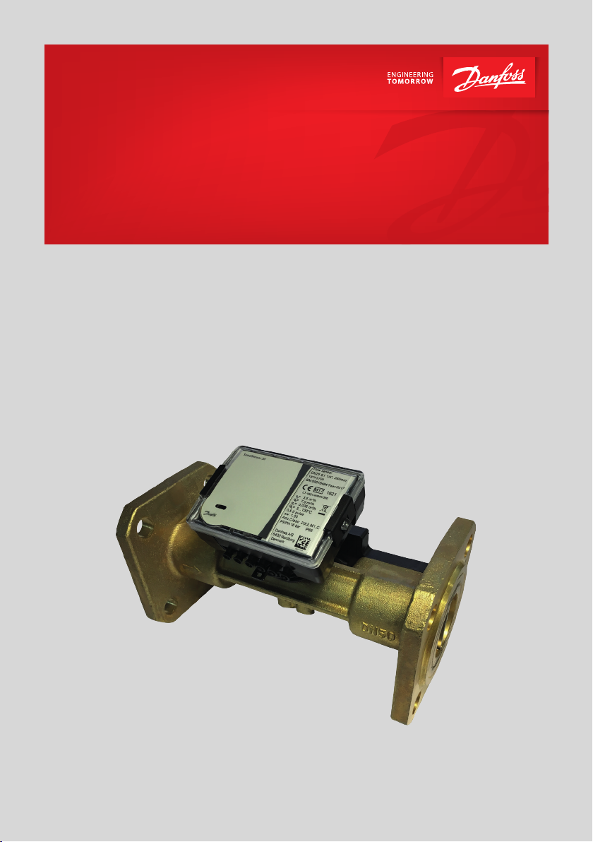
SonoSensor 30
Ultrasonic flow meter for heating and
cooling applications
Installation & User Guide SonoSensor 30
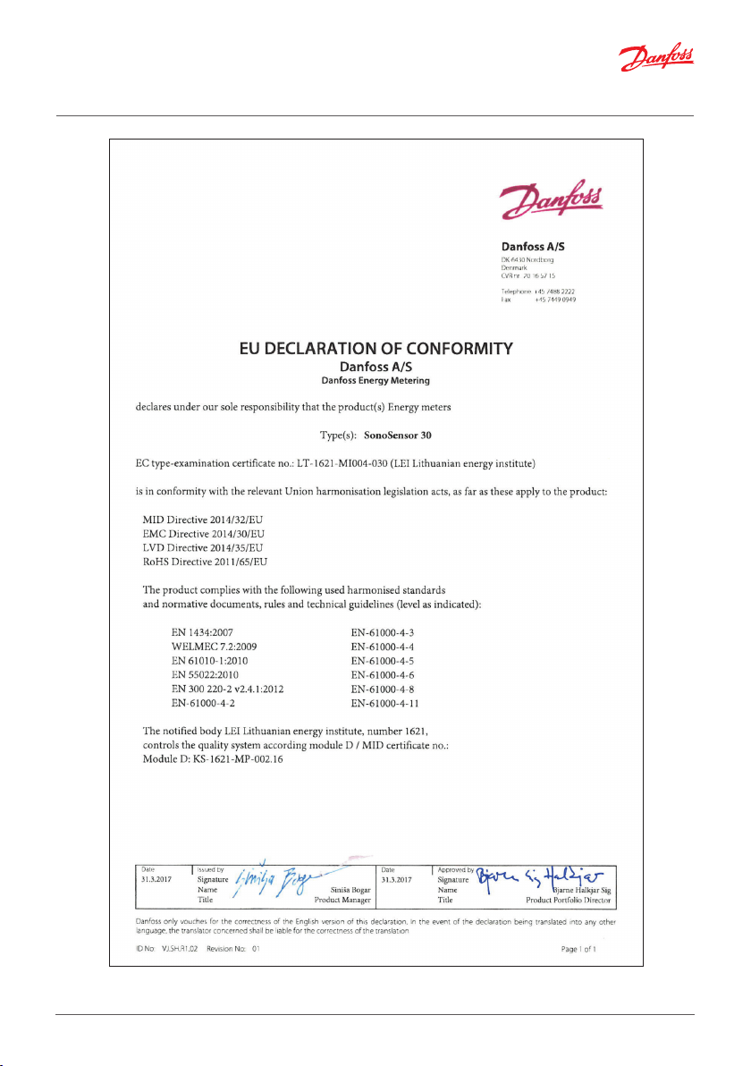
Note! To ensure latest version of declaration, please visit danfoss.com.
2 | © Danfoss | Energy Meters | 2020.11 AN271156466186en-010201

Installation & User Guide SonoSensor 30
Contents
1. Safety notes and product information .................................................................. 4
2. Installation ................................................................................................ 4
3. Electrical wiring ........................................................................................... 6
4. Commissioning ...........................................................................................7
5. Power supply .............................................................................................. 7
6. Disposal ................................................................................................... 8
7. Local Importer name and address ....................................................................... 8
2.1 Preparation ..................................................................................... 4
2.2 Installation of flow sensor ...................................................................... 4
2.3 Mounting of electronic unit.................................................................... 5
3.1 Flow pulse cable connection ................................................................... 6
3.2 External power supply module (if used) ....................................................... 6
3.3 Wiring SonoSensor 30 to energy calculator Infocal 9 ......................................... 6
4.1 Bleeding ........................................................................................ 7
4.2 Electronic unit sealing ......................................................................... 7
AN271156466186en-010201 © Danfoss | Energy Meters | 2020.11 | 3

Installation & User Guide SonoSensor 30
1. Safety notes and product information
Following instructions refer to the ultrasonic flow sensor. The regulations on the use of energy meters
must be observed! The flow sensor installation is only to be performed by an installation and/or electrical
contractor using personnel trained in the installation and use of electrical equipment and familiar with
the Low Voltage Directive. The relevant ESD regulations (electrostatic discharge) must be observed.
No liability is accepted for damage (especially to electronic circuits) resulting from failure to comply with
the ESD regulations. This installation guide is intended for trained personnel and does not contain any
basic working steps. The seal on the flow sensor must not be damaged! A damaged seal will result in
immediate invalidation of the factory warranty and verification.
2. Installation
2.1 Preparation
Only qualified personnel may install the equipment, following the requirements listed in this document.
More detailed instruction can be found on www.heating.danfoss.com.
Note! This product is approved for ambient temperature between 5-55° C. Avoid installation stress from
pipes and fittings. Flush the system.
2.2 Installation of flow sensor
Depending on the application the flow sensor is installed in the supply or return pipe of the system. The
flow sensor must be installed so that the direction of flow corresponds to the direction of the arrow on the
flow sensor. Calming sections are not needed before or after the flow sensor for sizes from DN15 to DN50,
calming sections of 5xDN before and 3xDN after the flow sensor are needed for sizes from DN65 to DN100.
Flow sensor can be mounted both vertically and horizontally in pipelines. Vertically mounting of the flow
sensor is allowed only if flow direction in the pipeline is from down to up.
The flange gaskets must match with the pipe diameter. During the installation gasket must be exactly
centered with the center of the pipe cross-section to avoid sticking out gaskets inside the pipe. The flow
sensor must always be filled with water. Avoid frost on the sensor. We recommend installing the flow
sensor in a tilted position. The minimum system pressure must be 1 bar to avoid cavitation. Avoid the flow
sensor installation near after the pumps which can also cause cavitation.
Make sure the flow sensor is installed sufficiently far away from possible sources of electromagnetic
interference (switches, electric motors, fluorescent lamps, etc...). The flow sensor should be installed in an
accessible position for service and operating personnel.
Min 45°
Min 45°
Pipe position: No limitations but avoid positions
where air can be collected.
4 | © Danfoss | Energy Meters | 2020.11 AN271156466186en-010201
Rotation in pipe axis: Flow sensor should be
angled in 45 to 315° to avoid air collection in flow
sensor.
Min 45°

Installation & User Guide SonoSensor 30
Inlet/outlet conditions
SonoSensor 30 sizes from DN15 to DN50 don’t need any calming sections before and after the flow sensor.
In order to maximize performance for sizes DN65, DN80 and DN100 it is necessary to have straight inlet
and outlet flow conditions 5xDN before and 3xDN after the flow sensor.
5 x DN
flow
3 x DN
2.3 Mounting of electronic unit
Direct mounting on ultrasonic flow sensor housing, turning every 90 ° C (only when the temperature of
the flow does not exceed 90 ° C)
a) On the flow sensor with a thread connection
Wall mounting:
Mounting on standard DIN-rail:
b) On the flow sensor with flange connection
max 3,5
min 2
Important: It is forbidden to attach the electronic unit direc tly to the wall if there is a risk that on the wall can be
condensed humidity or temperature of a sur face of a wall can fall lower than 5°C. In this case, it is recommended
to mount the calculator on the wall with an air gap not less than 5 cm.
AN271156466186en-010201 © Danfoss | Energy Meters | 2020.11 | 5

Installation & User Guide SonoSensor 30
3. Electrical wiring
3.1 Flow pulse cable connection
It is recommended to use copper wire cable with the cross-section 0.3 ... 0.5 mm2. By means of tweezers
remove a protective knoll from 1 sealant hole of electronic unit. Run the cable through the hole and
anchor with clamp. Use two wire connection methods –connect to the terminals 18 and 19 as shown in
the picture.
Terminal Nr. Description
18 Volume pulse output (+)
19 Ground (-)
3.2 External power supply module (if used)
Terminal Nr. Description
54 Mains supply 24 V AC/DC (bipolar)
55 Mains supply 24 V AC/DC (bipolar)
3.3 Wiring SonoSensor 30 to energy calculator Infocal 9
SonoSensor 30 in return pipe Infocal 9 terminal SonoSensor 30 in return pipe Infocal 9 terminal
18 (flow pulse) 52 (q2+) 18 (flow pulse) 10 (q1+)
19 (ground) 11 (q2-) 19 (ground) 11 (q1-)
Battery
24V AC/D C
3,6V
Pulse output
Measured flow rate is converted into the volume pulses which are transferred through pulse output
terminal. Pulse output class of flow output device: OD according to EN1434-2 + AC:2007. Maximum flow
cable length from electronic box to energy calculator or pulse reading device is up to 100m.
Values of output pulses:
Nominal (permanent) flow rate qp Pulse value, litres/pulse
0.6, 1.5, 2.5, 3.5 and 6.0 1
10, 15, 25, 40 and 60 10
6 | © Danfoss | Energy Meters | 2020.11 AN271156466186en-010201

Installation & User Guide SonoSensor 30
4. Commissioning
4.1 Bleeding
1. Bleed the system until the flow rate display is steady.
2. Make sure no error codes are displayed.
3. Check the display for a plausible indication of flow rate and temperatures.
4.2 Electronic unit sealing
1: Manufacturer adhesive seal sticker on the access to the adjustment activation jumper - verification seal.
2: Manufacturer adhesive seal sticker on the cover protecting electronic module - manufacturer security seal.
3: Mounting seal after installation
5. Power supply
SonoSensor 30 can be powered from lithium battery (12 years life time) or from external supply.
Battery
3,6V, 2,4Ah lithium battery with 12 years of battery lifetime is fitted in flow sensor. The battery is not to be
charged, replaced or short-circuited. Ambient temperatures below 55°C ensure the typical life of the
battery.
External supply
- power supply: 12V…42V DC or 12C…36V
- pulse current: 10mA
Caution
Used batteries must be disposed of at suitable waste collection points. There is risk of explosion if
replaced battery is incorrect type.
AN271156466186en-010201 © Danfoss | Energy Meters | 2020.11 | 7

6. Disposal
This symbol on the product indicates that it will not be treated as household waste. It
must be handed over to the applicable take-back scheme for the recycling of electrical
and electronic equipment. For more detailed information about the recycling of this
product, please contact your local municipal office.
Item Material Disposal
Battery
PCBA with display and
communication module
Cables Copper with PUR or PVC jackets Cable recovery
Flow sensor
(including transducer
and liner)
Transducer PZT, stainless steel, PEI Approved deposit for PZT
Other plastic parts PC, PPS, PEI, TPE Plastic recovery
AA-cell Lithium/thionyl chloride 620 mg
Lithium
Coppered epoxy laminate components
soldered on, PC, TPE
Brass, stainless steel, PPS Metal recovery
Approved deposit for lithium
batteries
Electronic waste
7. Local Importer name and address
For goods delivered to UK, importer name and address is:
Danfoss Ltd.
Oxford Road
UB9 4LH Denham
UK
AN271156466186en-010201 © Danfoss | Energy Meters | 2020.11 | 8
 Loading...