

Page 1
Operating Guide
SonoReCon Software
Table of Contents
Introduction ........................................................................................................................................ 2
System Requirements ................................................................................................................................................. 2
Installation ....................................................................................................................................................................... 2
Installation of the SonoReCon Software ..................................................................................................... 2
Installation of the SonoReCon USB Hardware Driver ............................................................................. 2
Starting up the SonoReCon Software .......................................................................................................... 2
Using Lists ........................................................................................................................................................................ 4
Main Window ....................................................................................................................................... 6
General settings ............................................................................................................................................................ 6
Device state ..................................................................................................................................................................... 7
Device meter list ............................................................................................................................................................ 7
Received meter list ....................................................................................................................................................... 8
Get GSM / UMTS network info ................................................................................................................................. 9
Device configuration .......................................................................................................................... 10
General device settings .............................................................................................................................................. 10
Device FTP settings ...................................................................................................................................................... 11
Device radio reading and FTP upload settings ................................................................................................. 13
Estimated battery life time ............................................................................................................................... 16
Device radio meter filter settings ........................................................................................................................... 16
Remote device configuration ................................................................................................................................... 16
Remote configuration ................................................................................................................................................. 17
Installation Test Mode ................................................................................................................................................. 18
Radio Checklist Mode .................................................................................................................................................. 21
How to Configure an SonoReCon (Standard Setup) ........................................................................ 23
Download and display uploaded files and device protocols ....................................................................... 25
Data view ......................................................................................................................................................................... 26
FTP file view ........................................................................................................................................................... 27
Radio telegram log view ................................................................................................................................... 32
Event log view ....................................................................................................................................................... 33
FTP upload log view ........................................................................................................................................... 34
Conversion of GP2 files to CSV files .................................................................................................. 35
Format of the converted CSV files .......................................................................................................................... 35
Format of special entries of the converted CSV files ....................................................................................... 35
© Danfoss | 2019.05 VU.SH.F1.02 | 1
Page 2
Operating Guide SonoReCon
Introduction
System Requirements
Installation
The SonoReCon is a radio receiver for wireless
M-Bus resource meters, which is equipped with
a GPRS / UMTS modem and a data concentrator.
A lithium battery pack assures operating times
up to several years without an external power
supply. The SonoReCon is used in places where
data from radio consumption meters (electricity,
gas, water and heat) must be collected, stored
and transmitted to a central station, but where
there is no power supply available.
Before installing the SonoReCon software, please
check if your PC complies with the minimum
requirements:
• Windows 7, 8 or 8.1 operating system
(updated to the latest version)
• 1 GHz processor
• 4 GB memory
• 20 MB free hard disk space
• 1 free USB port
• Internet connection (only once to install
the USB driver)
Installation of the SonoReCon Software
Execute the installation file SonoReCon_Setup.
exe on your PC.
If there is already a former version of the
software installed, the user has to remove this
version prior to installing the current version.
If the version number of the already installed
version is inferior to the version to be installed
the removing is done automatically. Otherwise,
the user has to do it manually.
Installation of the SonoReCon USB Hardware
Driver
The SonoReCon uses an USB standard driver,
which is already installed on most Windows
PC. If this is not the case the automatic driver
search mechanism of Windows is downloading
the current USB driver. However, an internet
connection is necessary in this case.
Due to the water tight enclosure with protection
rating IP67 or IP65 (depending on options)
and the operating temperature range of
-20°C to +55°C the SonoReCon can be used in
non-weather protected outdoor installations
(temperate climate).
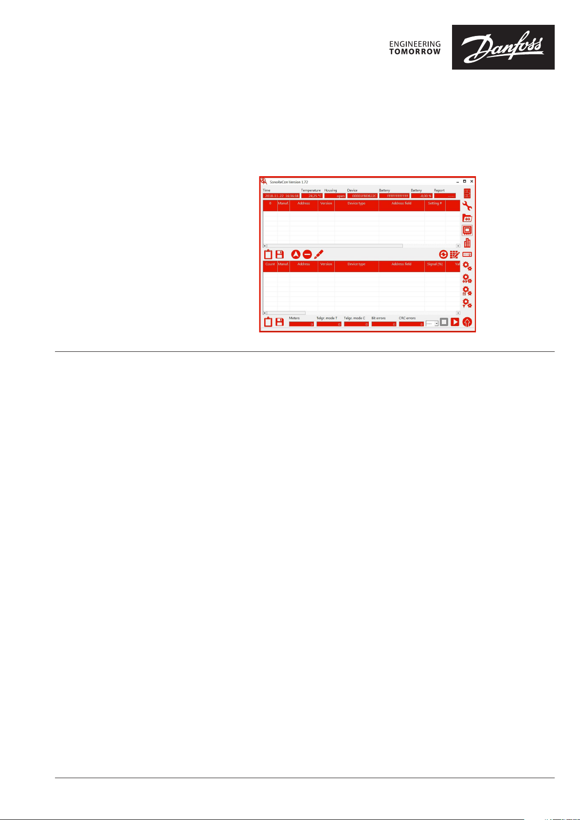
Starting up the SonoReCon Software
The SonoReCon software is started up by
double-clicking on the program icon on your
desktop or the respective tile:
Having installed the software for the first time,
the following dialog for selecting the program
language appears (English, French or German).
Note: You may change the language afterwards at the
settings dialog.
2 | VU.SH.F1.02 © Danfoss | 2019.05
Page 3
Operating Guide SonoReCon
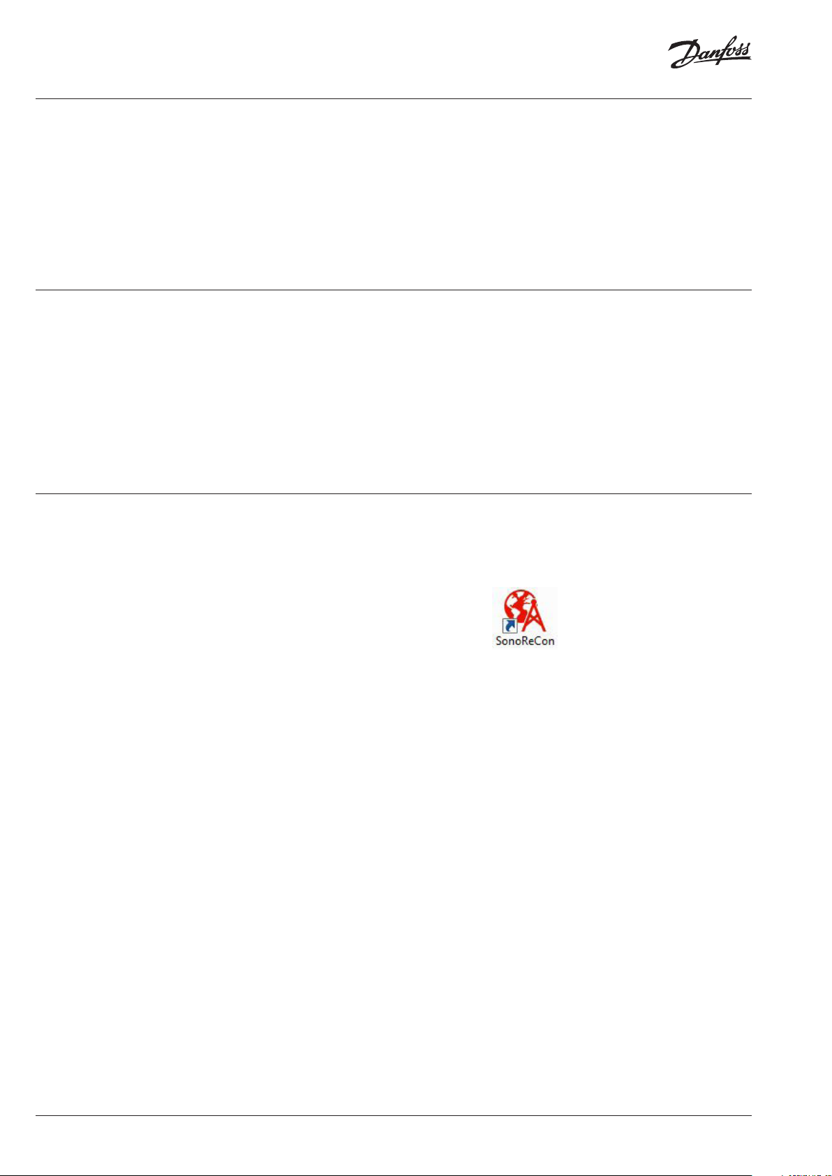
Installation (continuous) The software recognizes automatically if a
SonoReCon is connected to one of the USB
ports of your PC or if it is disconnected. If there
As soon as a SonoReCon device is connected the
progress bar shows the connection progress.
is no SonoReCon connected and the software is
started, the window below appears:
VU.SH.F1.02 | 3© Danfoss | 2019.05
Page 4
Operating Guide SonoReCon
Installation (continuous)
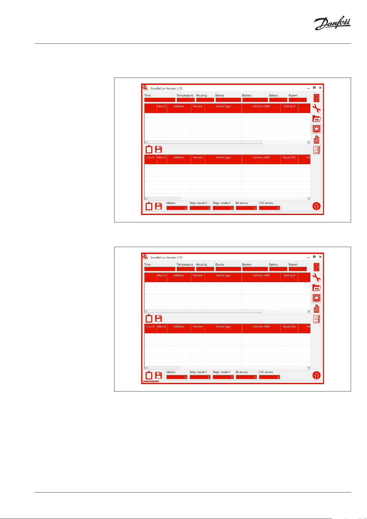
After two to eight seconds the connection is
established, and the window below is shown:
If the access to the USB configuration interface
of the device is password protected than
the following window appears before the
connection with the device is completely
established:
Using List
Enter the correct password and press OK
afterwards. Without the correct password no
access to the device is possible.
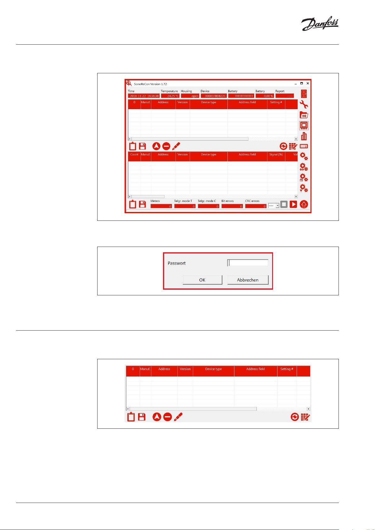
The software contains several lists which have all
the same general functionality.
Each list has got two buttons for exporting the
list data, either to the clipboard or to a file. The
export to the clipboard is done only for selected
entries. The export to a file is always done for all
entries of the list regardless if they are selected
or not.
4 | VU.SH.F1.02 © Danfoss | 2019.05
Page 5
Operating Guide SonoReCon
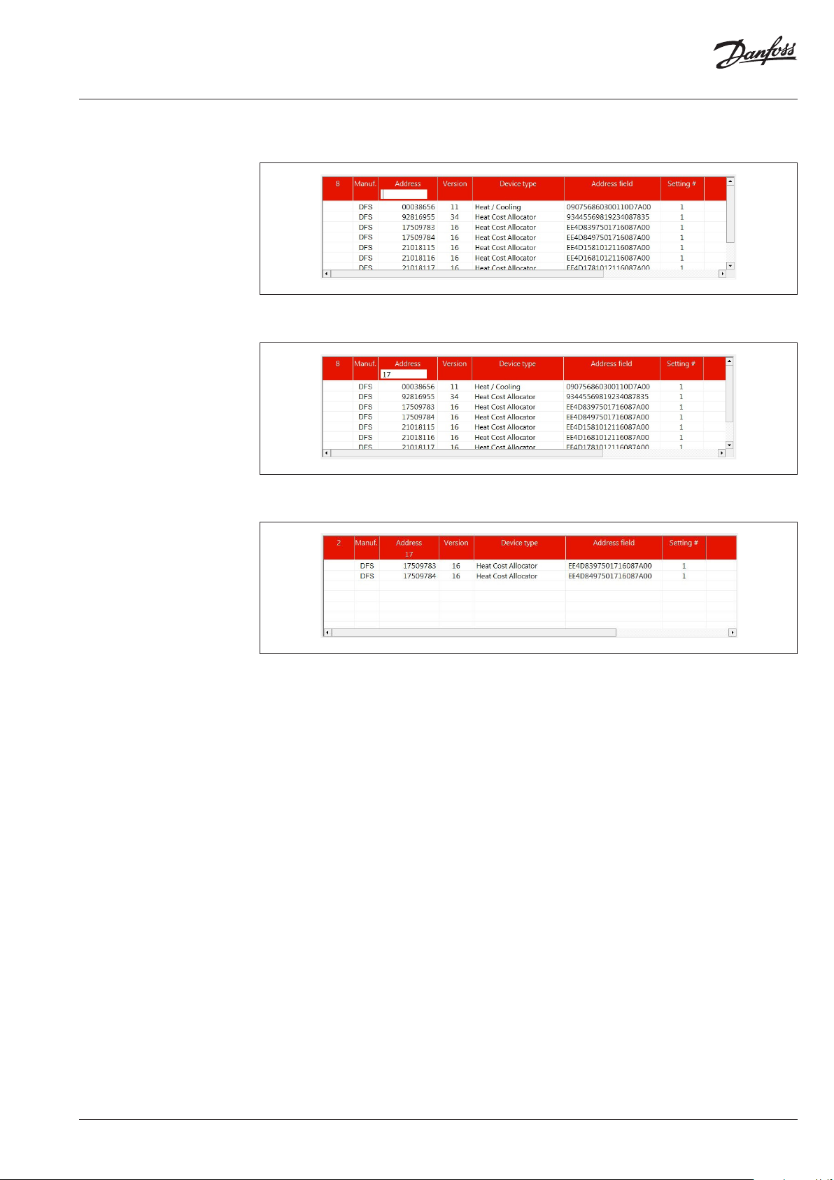
Using List (continuous) Column filters can be used to limit the amount
of list entries shown. To activate a filter left-click
Enter a filter value. If you e.g. want to limit the list
entries to only those starting with “17”, enter 17:
Press return afterwards and you can see that
the filter value appears on the second line
on the header of the respective column (address
column has been clicked in the example below):
of the column header and only those entries
corresponding to the filter criteria are displayed.
You may filter the list by multiple columns
simultaneously.
To remove a filter, you may either left-click on the
respective column header and delete the filter
entry.
To remove all column filters at once you may
right-click somewhere on the column header.
This clears all column filter values.
VU.SH.F1.02 | 5© Danfoss | 2019.05
Page 6
Operating Guide SonoReCon
Main Window
General settings
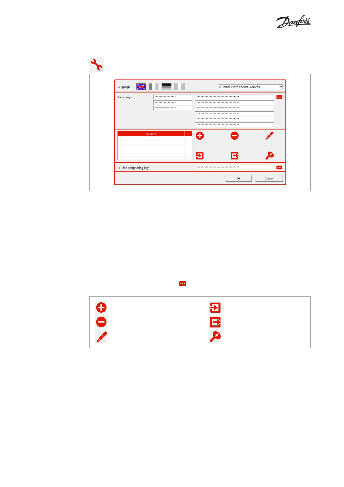
By clicking on this button, the dialog shown below opens.
The program language can be selected by
clicking on one of the flags.
The user may also choose if numbers are to be
displayed with decimal comma or decimal point.
If the software should also be able to decipher
and interpret radio telegrams the user has to
provide the respective keys. A maximum of
three different 64 bit keys (left hand side) and
six different 128 bit keys (AES 128, e.g. for OMS,
right hand side) may be entered, respectively.
Additionally, it is possible to enter a list of meter
specific radio keys. For that purpose, the user
has to enter meter address and radio key of one
specific meter. If the meter with the respective
address is received the stored radio key is used
for deciphering. This function is only available
with AES128 radio keys.
If the user decides to encipher the uploaded files
also, he can enter the FTP file deciphering key
here.
The software will try all three / six keys until a
radio telegram is deciphered. To gain processing
speed during radio telegram reception you
should set unused key entry fields to “FFFF….”.
To show the keys in clear text click on the
button.
Add a new meter address with radio key.
Remove the selected meter addresses and
radio keys from the list.
Edit the selected meter address and radio key.
Import a list of meter addresses and radio keys
from a file.
Expor t the list of meter addresses and radio
keys to a file.
Import one or multiple KEM files with meter
address and radio key.
6 | VU.SH.F1.02 © Danfoss | 2019.05
Page 7
Operating Guide SonoReCon
Device State
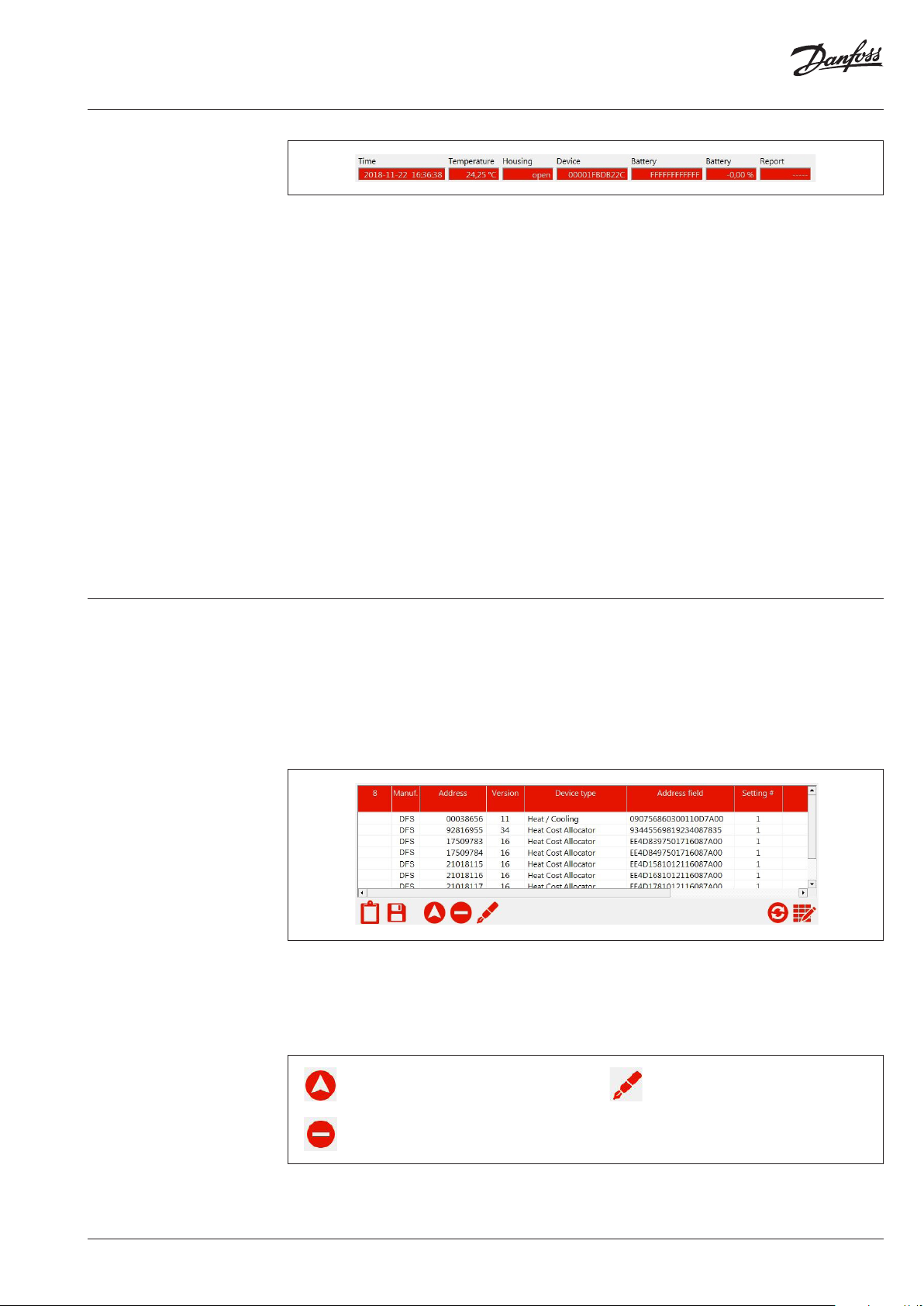
After connecting a device, the above shown information are updated once per second:
Time
The current device time and date. Please note
that the SonoReCon has not got a long-term
buffer for the internal clock. That is if there is
no supply for the device either by the main
battery pack, the wall plug power supply or by
USB, the internal clock will continue running
for about 3…5 hours and then stop and drop
back to 2000-01-01 00:00:00. So during onsite
installation the internal device clock must be
set to the current time. Usually, this is done
automatically by this software at connection
time. There is also the option to automatically
set the clock against an internet time server at
every FTP upload. In this case it should be noted
that the automatic clock set option against an
internet time server is always setting the clock to
standard time (not daylight saving time). If the
PC is set to daylight saving time there might be a
difference between PC time and device time.
Temperature
The internal device temperature.
Housing
If the housing is opened or closed.
Device
The device’s complete serial number in
hexadecimal format.
Battery
The battery pack’s serial number in hexadecimal
format (if a battery pack is connected).
Battery
The remaining battery capacity in percent (if a
battery pack is connected).
Report
A report about the currently ongoing process in
the device:
• ----- device is currently in idle state
• RADIO device is currently reading
radio devices
• FTP device is currently performing
an FTP upload
Device meter list The SonoReCon device may be configured for
reading radio meters in two ways. Either it is
opening the radio receiver for a given amount
of time and all radio meters captured are
registered or the user may configure a meter
list. In later case only the radio meters on the
list are captured and registered. This feature has
got the advantages of not spoiling the available
The device meter list may contain up to 1000
meters, however, it is advised to use this feature
only to an amount of 100 to 200 meters since the
radio address comparison process may consume
too much time thus leading to missed radio
telegrams.
Add one or multiple meters from the list of
received meters (see nex t chapter) to the
meter list.
Remove one or multiple meters from the
device meter list (use multiple selection option
with SHIFT or CTRL keys).
data storage space for unwanted radio meter
telegrams and also closing the radio receiver as
soon as all meters from the list are received, thus
saving on battery capacity.
To configure a meter list the user has to start a
radio reception and select the radio meters to
add from the received meters (see next chapter).
If more than 100 to 200 meters must be received
it is better to not use the meter list but to capture
and register all radio telegrams received.
Regarding the meter list the user has got the
following options:
Modify one or multiple device list entries
(use multiple selection option with SHIFT
or CTRL keys). After having clicked on this
button the following dialog appears for each
selected entry of the list. To close the process
prematurely the user may click on “Cancel”
instead of “OK” for the next device.
VU.SH.F1.02 | 7© Danfoss | 2019.05
Page 8
Operating Guide SonoReCon
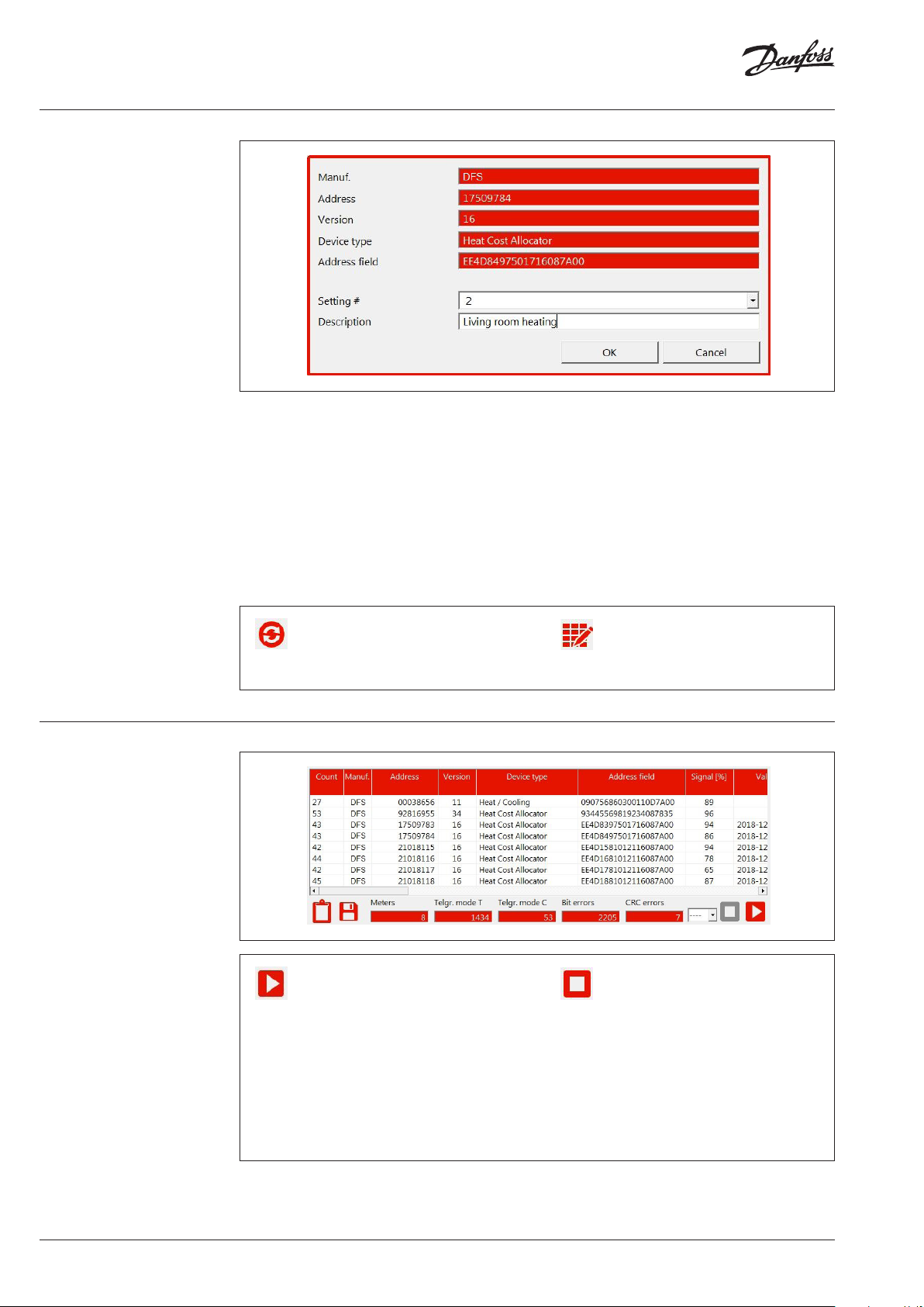
Device meter list (continuous)
Received meter list
The user may now select the reading profile for
the given radio meter and enter a description
for the meter. The read-out process may be
configured for 3 different profiles (containing the
radio reading interval and the duration of radio
reception for each reading). Thus it is possible
to read-out important meters more often than
less important meters. The “Setting #” associates
the selected radio meters to one of the three
radio reading profiles. The radio reading profiles
are configured at the radio reading parameter
dialogue (see below).
Read the current meter list from the device.
The meter list of the device is not automatically
read during e.g. the connection process.
Therefore, the user must load the list manually
before proceeding with any modifications.
By clicking on “OK” the changes are taken and
the dialogue switches to the next meter (if more
than one meter had been selected). Clicking on
“Cancel” cancels the modifications on the current
meter and closes the dialogue. Please note that
modifications previously confirmed with “OK”
are still taken. Please note also that by editing
the device list only the displayed copy of the list
is modified. It is not automatically written to the
device (see below).
Read the current meter list from the device.
The meter list of the device is not automatically
read during e.g. the connection process.
Therefore, the user must load the list manually
before proceeding with any modifications.
To test the radio reception of the device at a
specific spot or to receive the radio meters
to build a radio meter list the user may start
a radio reading. The radio reading may either
be started for an unlimited amount of time
(just up to the moment where the stop button
is pressed) or the time span may be limited
by selecting an entry from the list on the left
hand-side of the button. Having started the
radio reading all received meters are displayed
continuously on the list (one entr y per meter).
Please note that the radio receiver is switched
off if there is an FTP upload in progress (check
the respective repor t entry at the top of the
windows).
Stop radio reception. Only if the radio
reception is stopped the user may e.g. build its
meter list or configure the device. If the radio
reception is in progress other functions are
blocked.
8 | VU.SH.F1.02 © Danfoss | 2019.05
Page 9
Operating Guide SonoReCon
Received meter list
(continuous)
Get GSM / UMTS network
info
Meters
The total number of different radio meters
received.
Telgr. mode T
The total number of correct wireless M-Bus
mode T telegrams received.
Telg. mode C
The total number of correct wireless M-Bus
mode C telegrams received.
Bit errors
The total number of telegrams with bit errors
received.
CRC errors
The total number of telegrams with CRC errors
received.
The list of received meters is used to build up the
device meter list. By selecting one or more
entries (multiple select by SHIFT and ALT keys)
and clicking the button the selected meters
are added to the list. This is only possible if the
reading process has been stopped.
At the right hand side end of the list with the
received meters you can find the telegram in
hexadecimal format.
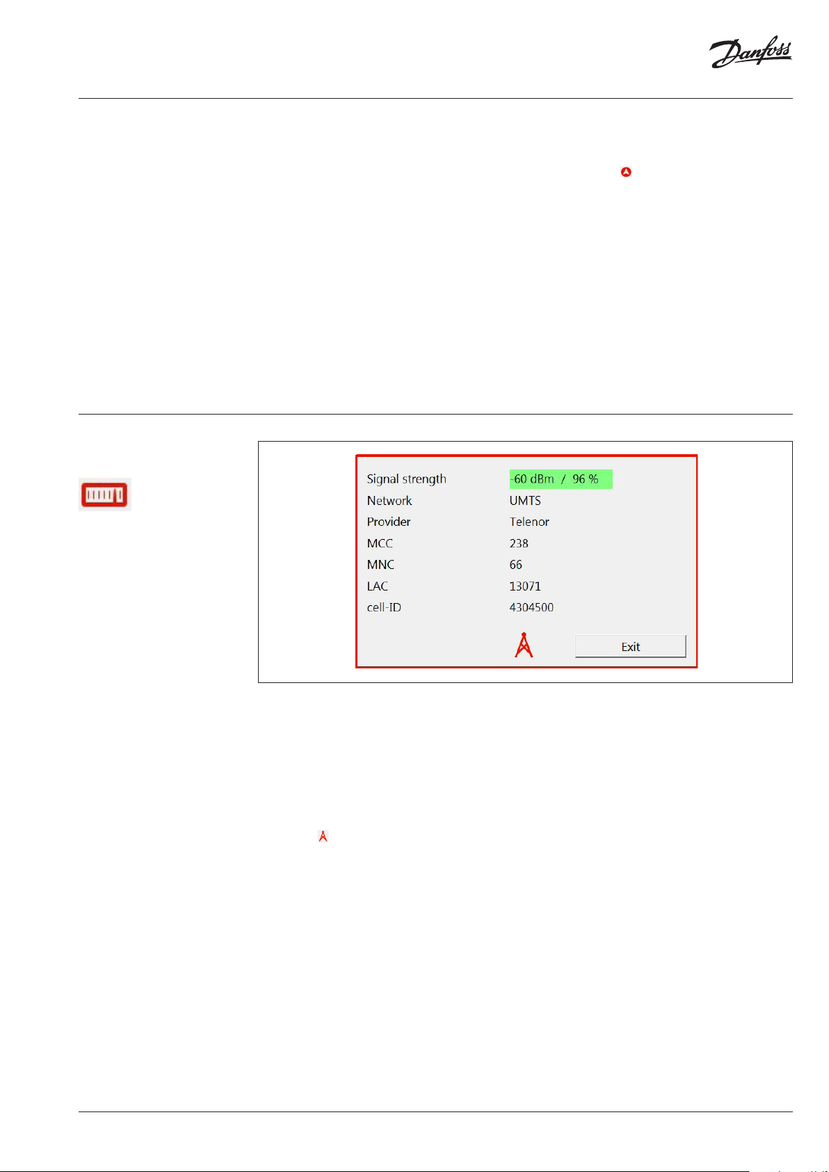
To figure out where to place the device best for
an optimum GSM / UMTS network connection it
is possible to start the GMS / UMTS network
monitor. After clicking on the button above it
takes about 30 to 60 seconds before the device
internal modem is started up. Then, if there is a
GSM / UMTS network connection, the network
parameters are shown with an update frequency
of once per second. If the GSM / UMTS network
cell was identified it is also possible to locate it by
clicking on (only available if an internet
connection is active and if the network cell can
be found in the database).
The most important parameter for good data
transmission is the signal strength. This value
should be above 35 % (shown in green). If the
signal strength is below 35 % data upload may
still be possible but the probability of incomplete
files increases.
Please note that a SIM card must be inserted
into the device and the SIM PIN must be
correctly configured (see below at device
configuration / FTP settings). If there is an
incorrect SIM PIN configured the SIM card will
be accessed more than three times with this
incorrect SIM PIN and, therefore, it will be
blocked. In this case you have to put the SIM
card e.g. in an appropriate portable phone
and use the SIM PUK to unblock the SIM card.
By clicking on “Exit” the GMS / UMTS network
monitor is closed. It takes about 10 seconds
after closing this windows to shut down the
device internal modem. During this time it is not
possible to start e.g. an FTP test upload.
VU.SH.F1.02 | 9© Danfoss | 2019.05
Page 10
Operating Guide SonoReCon
Device configuration
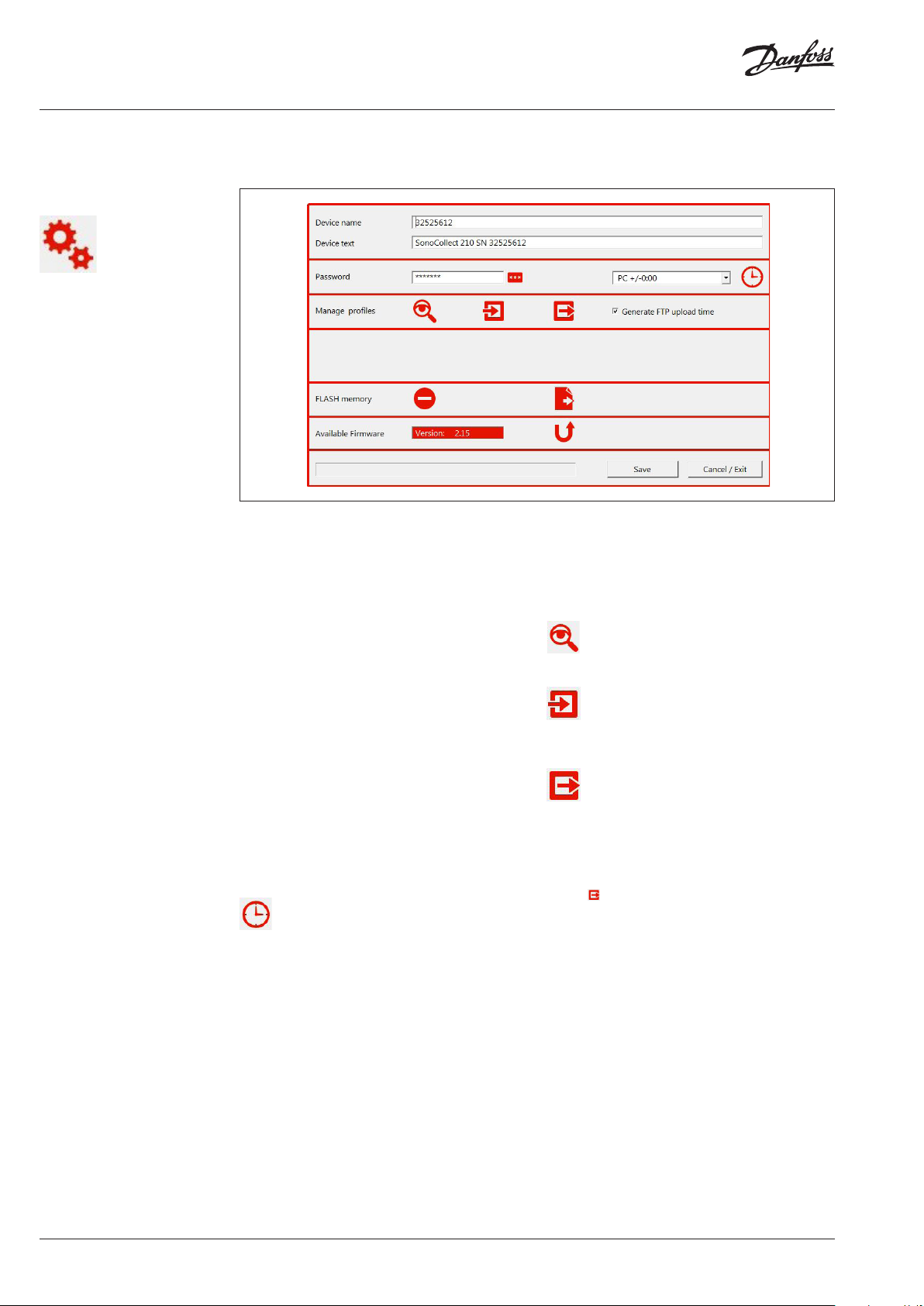
General device settings
There are four different device configuration
buttons invoking four different configuration
Device name
The device name must be programmed to a
unique name by the user. This name is used as
name for the uploaded files. Click on “Save” to
write the modifications to the device.
Device text
The device text is free text for e.g. a description
of the installation site. Click on “Save” to write the
modifications to the device.
Password
If the password stays on the default settings
of “SonoReCon” or if the password is blank the
configuration of the device is not password
protected. If the password is set differently the
user has to enter a password before being able to
access the device configuration. Click on “Save”
to write the modifications to the device.
Please note that the password protection
starts only after the device has once been
disconnected from the USB interface. You must
then wait up to the point where the software
recognizes the disconnection (the serial number
of the device is no longer shown at the headline)
before reconnecting the USB interface.
Set the device clock according to the clock of the
Windows PC. The user may set a deviation by
selecting the appropriate value from the list on
the left hand-side of the button.
It is also possible to set the device clock
automatically using an internet clock at FTP
upload time (see below). However, then the
time zone is set automatically to the time zone
of the Windows PC and the deviation eventually
entered here is not used.
dialogues: general settings, FTP settings, radio
reading settings, radio telegram filter settings.
Manage profiles
Profiles are complete configurations of a device.
With this feature
it is possible to configure a device once and
copy this configuration to multiple other devices
without having to configure all parameters one
by one.
Shows the complete configuration (profile) of
the device in an overview list.
Read the complete configuration (profile) of a
device from a file and write it to the connected
device.
Write the complete configuration (profile) of the
connected device to a file.
Generate FTP upload time
If this option is checked then the configured FTP
upload time (using the profile write to device
button ) is not the time stored in the profile
but the time is automatically generated using
the serial number of the device. This guarantees
a certain equal distribution of FTP upload times
over the day if you are using many devices. If
all devices are uploading at one specific time
per day your FTP server may be overloaded and
denying upload requests. Therefore, it is strongly
advised to use this option.
FLASH memory
The FLASH memory of the device contains the
data logger memory as well as e.g. the meter list.
To reset a device it may be completely erased. It
is also possible to perform a memory dump for
debug purposes.
10 | VU.SH.F1.02 © Danfoss | 2019.05
Page 11
Operating Guide SonoReCon
General device settings
(continuous)
Clears the complete FLASH memory, thus erasing
all data logger memory as well as the meter list
and all protocol entries. This process takes about
60 seconds to complete.
Write the complete FLASH memory of the device
to a file. This function should only be used for
debugging purposes if there are problems with
the device. The process takes about 40 minutes
to complete. The user may only interrupt the
process by pressing ALT+F4.
Device FTP settings
Starts the firmware update. The manual start
of a firmware update is usually not necessary,
since at connection time the software checks
if the firmware of the device is older than the
current version supplied by the software. If this
is the case the device firmware is automatically
updated. It is not possible to downgrade the
device firmware version. Firmware updates with
firmware versions inferior or equal to the current
device firmware version are ignored by the
device.
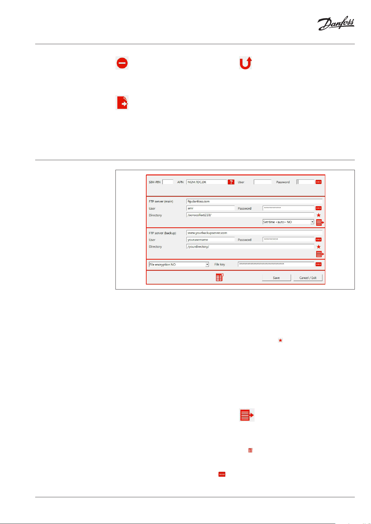
SIM-PIN
Configuration of the PIN of the SIM card
(telephone card). Your phone card must have PIN
verification enabled.
APN
Access Point Name for the provider you are
using. Please check with the provider of your SIM
card which APN to use. You may also click on the
button at the right hand-side of the entry field
to get a list of standard APN (supplied without
liability).
User
If the APN needs a user name the user must enter
it here.
Password
If the APN needs a password the user must enter
it here.
FTP server (main)
The URL or IP of the FTP server where to upload
the logged radio meter data. This is the server
which is tried first. If this upload fails, the device
does a second attempt to the backup server.
User
The user name to access the main FTP server.
Password
The password to access the main FTP server. To
show the password in clear text click on the
button.
Directory
The directory on the main FTP server where to
upload the files with the logged radio meter
data. Please use a slash ‘/’ at the beginning and
at the end of the directory name. Do not use
backslashes ‘\’. If the given directory does not
already exist on the main FTP server the user
may click on the button to create the given
directory.
Set time <auto>
Enables or disables the automatic time setting
of the device internal clock by getting the time
from an internet server at every FTP upload. If
the automatic time setting is enabled the device
time is always set to the standard time (usually
winter time) of the time zone provided by the
PC used for configuring. So the time zone on the
configuring PC must be correct.
Perform an FTP test upload using the main FTP
server parameters. This function can be used to
verify the connection to the server. It is possible
to supervise the upload process by clicking on
the button (see below).
VU.SH.F1.02 | 11© Danfoss | 2019.05
Page 12
Operating Guide SonoReCon
Device FTP settings
(continuous)
FTP server (backup)
The URL or IP of the FTP server where to upload
the logged radio meter data in case the upload
to the main FTP server has failed.
User
The user name to access the backup FTP server.
Password
The password to access the backup FTP server.
To show the password in clear text click on the
button.
Directory
The directory on the backup FTP server where
to upload the files with the logged radio meter
data. Please use a slash ‘/’ at the beginning and
at the end of the directory name. Do not use
backslashes ‘\’. If the given directory does not
already exist on the main FTP server the user
may click on the button to create the given
directory.
Perform an FTP test upload using the backup FTP
server parameters. This function can be used to
verify the connection to the server. It is possible
to supervise the upload process by clicking on
the button (see below).
String length limitation:
FTP ser ver name 80 characters
FTP user 40 characters
FTP password 40 characters
FTP directory 80 characters
The character “$” may not be used.
File key
If the file encryption option is set to “YES” than
this key is used to encipher the uploaded radio
meter data files. To show the key in clear text
click on the button.
The device has got a reserved memory for
keeping the protocol of the last FTP upload.
By pressing this button the upload protocol is
shown. Since the protocol is updated during the
upload process it is possible to follow it in real
time.
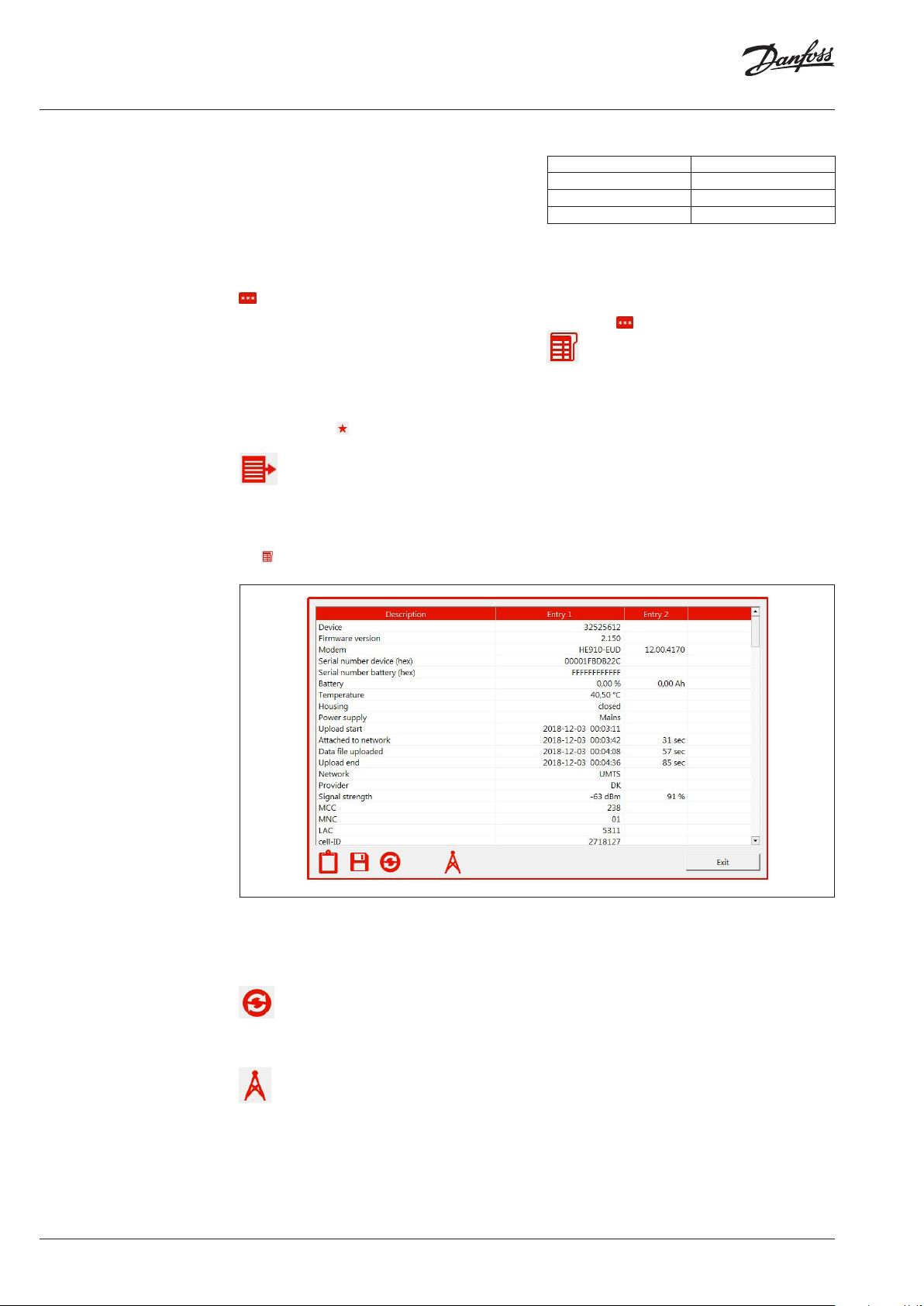
This dialog shows the protocol of the last FTP
upload. In the following list only some of the
entries are explained, the rest is self explaining
or is only be ment to be used by specialist for
debugging purposes.
Upload start
The device registers the time the upload
is started, the time it has established the
connection to the internet, the time the radio
meter data file has been uploaded and the time
the upload has finished. The time spans are also
calculated and displayed.
Refresh the protocol list. If an FTP upload is in
progress the user may press the refresh button
any time to show the current state of the upload.
Network
GSM or UMTS
Provider
The name of the network provider.
Signal Strength
If during the FTP upload process the used GSM /
UMTS network cell has been identified and if this
network cell is listed in the database a click on
this button will show the network cell location
on a map (internet connection necessary).
The network signal strength.
MCC
Mobile Country Code, a code identifying the
country where the network cell is located.
12 | VU.SH.F1.02 © Danfoss | 2019.05
Page 13

Operating Guide SonoReCon
Device FTP settings
(continuous)
MNC
Mobile Network Code, a code identifying the
mobile network.
LAC
Location Area Code, a code identifying the area
where the network cell is located.
cell-ID
Identifier of the network cell
IMSI
International Mobile Subscriber Identity, a
unique number to identify the SIM card.
Bytes uploaded
The number of data bytes uploaded.
Energy used
The total battery capacity used during the
upload process calculated by the measured realtime current and the duration of the FTP upload.
Max. current
The maximum current measured during the FTP
upload process.
The following list contains the AT commands
used by the internal GPRS / UMTS modem to
perform the upload. The result code is either
OK or error plus the number of retries. The most
important commands are explained below:
STIA
Opening the interface to the SIM card for reading
it. If the upload process fails at this step the SIM
card is not readable.
CPIN
Programming the PIN of the SIM card. If the
upload process fails at this step the PIN is not
correct.
MONI
Attaching to the GSM / UMTS network and
retrieving the network parameters. If the upload
process fails at this step the GSM / UMTS signal
strength is too small or there is not network
available.
SGACT
Attaching to the APN. If the upload process
fails at this step the connection to the internet
was not possible. This may be caused by an
overcharged APN (retry later on), incorrect
APN, incorrect APN user name, incorrect APN
password or a SIM card not qualified for IP data
connections.
FTPOPN
Opens the respective FTP server. If the upload
process fails at this step the FTP credentials are
not correct.
Device radio reading and
FTP upload settings
VU.SH.F1.02 | 13© Danfoss | 2019.05
Page 14

Operating Guide SonoReCon
Device radio reading
and FTP upload settings
(continuous)
This dialog configures the radio reading intervals
and durations and the FTP upload times.
For the radio reading 3 different profiles may
be configured. However, these profiles are only
used if the reading by device list is selected
(option “Use device list” selected).
If the device list reading is not used only the
profile 1 configurations are used.
Since the device may be powered by its internal
lithium battery pack or by a wall plug power
supply there are different settings for battery
(BAT) or power supply (PWR) for each profile,
respectively. Therefore, there are a total of six
settings configurable:
BAT 1: profile 1, battery supply
PWR 1: profile 1, power supply
BAT 2: profile 2, battery supply
PWR 2: profile 2, power supply
BAT 3: profile 3, battery supply
PWR 3: profile 3, power supply
Examples:
The same is valid for the FTP upload times. Either
the user chooses to use the same FTP upload
times for battery and power supply (option “As
with batteries” is selected) or he may configure
different settings for battery and power supply.
For each of the six radio reading settings the
following options are available:
Interval
Sets the interval between two consecutive radio
readings.
Span
Sets the duration of the radio reception per radio
reading. If the option “Use device list” is selected
the radio receiver is shut down as soon as all
meters from the list have been received. In this
case, therefore, the span gives the maximum
radio reception duration.
High def.
By selecting this option it is possible to define
a period during the day where a different radio
reading interval is used.
The device receives the radio meters once per hour and the receiver stays open for 75 seconds.
This setting is used for battery and power supply.
With battery supply:
The device receives the radio meters once per hour and the receiver stays open for 75 seconds.
With power supply:
The device receives the radio meters every 15 minutes and the receiver stays open for 3 minutes.
The device receives the radio meters once per hour and the receiver stays open for 75 seconds.
Between 07:00 and 08:59 every day the device receives the radio meters every 15 minutes.
The setting is used for battery and power supply.
With battery supply:
The device receives the radio meters once per hour and the receiver stays open for 75 seconds.
Between 07:00 and 08:59 every day the device receives the radio meters every 15 minutes.
With power supply:
The device receives the radio meters every 15 minutes and the receiver stays open for 3 minutes.
Between 06:00 and 10:59 ever y day the device receives the radio meters every 5 minutes.
14 | VU.SH.F1.02 © Danfoss | 2019.05
Page 15

Operating Guide SonoReCon
Device radio reading and
FTP upload settings
(continuous)
Examples:
The logged radio meter data are uploaded at the 2., 12. and 22. of each month at 04:13.
The setting is used for battery and power supply.
With battery supply:
The logged radio meter data are uploaded at the 2., 12. and 22. of each month at 04:13.
With power supply:
The logged radio meter data are uploaded every day four times a day starting at 07:15 (then at 13:15,
19:15 and 01:15).
It is possible to define multiple uploads per day. The upload are then performed in equidistant time
intervals always starting at the given time, e.g.:
2 / day two uploads with an interval of 12 hours in between
8 / day eight uploads with an interval of 3 hours in between
Notes:
For the 30th and the 31st day selected the following rules
apply:
If in a month with only 30 days instead of the 30th and the
31st the 29th and the 30th days are used for FTP upload
If in a month with only 28 days instead of the 30th and the
31st the 27th and the 28th days are used for FTP upload
If in a month with only 29 days instead of the 30th and the
31st the 28th and the 29th days are used for FTP upload
Option: “compact frame”
For radio meters sending so called “full frames”
and “compact frames” alternately this option
should be checked. Usually these radio meters
are sending one full radio frame with all
information necessary to decode the meter
values and afterwards seven compact radio
frames which are only containing the values but
not e.g. the physical unit etc. These compact
frames cannot be interpreted by this software.
Since the device is normally only recording the
first radio telegram received, this may be a full
frame or a compact frame.
Note:
At the FTP with batteries options it is also possible to set
the number of daily uploads to 288, which is once every 5
minutes. This option may be used for testing. However, it
is advised to use the following settings if 288 FTP uploads
per day are selected:
• The FTP upload time setting is ignored for 288 FTP
uploads per day. The FTP upload starts always at
2 minutes after the full 5 minutes, e.g. 00:02, 00:07,
00:12, 00:17, 00:22, and so on.
• The radio reception must be set to
- Interval = 5 minutes
- Span = 105 seconds
Since compact frames are not interpretable it is
necessary to get the full frame sent only every
eight time. If this option is checked, the device
is not recording one radio telegram of a meter
sending full / compact frames alternately but
eight radio telegrams in a row. Therefore, at least
one full frame should be recorded.
Use device list
If this option is checked the device is only
recording radio telegrams of the radio meters
in the device list. All other radio telegrams are
ignored. If this option is not checked all radio
meters received are recorded.
VU.SH.F1.02 | 15© Danfoss | 2019.05
Page 16

Operating Guide SonoReCon
Estimated battery life time
Device radio meter filter
settings
At the bottom of this dialog there is an entry field
showing the estimated battery life time for the
given radio reading / FTP upload configuration
for reading 10 meters or 100 meters, respectively.
It should be noted that these values are only
estimated values calculated for standard
FTP upload times. Especially, if the GSM /
UMTS network signal strength is low or the
GSM / UMTS network is overloaded the FTP
upload times may increase significantly and,
therefore, lowering the battery life time
significantly.
For the estimated life times a full battery
pack is assumed.
Remote device
configuration
If radio meter logging is used without a device
list (option „Use device list“ is not selected) the
user may limit the reception of unwanted radio
meters by using filters. It is possible to configure
two types of filter: filtering of the manufacturer
code of the radio telegrams or filtering of the
device type field of the radio telegrams.
A maximum of 12 filter values may be entered for
each filter type, respectively.
Additionally, it is possible to define if the filter
values are used to include or exclude the radio
telegrams.
It is also possible to remotely configure devices.
For this purpose a special configuration file is
uploaded to the FTP server where the device
places its data logger files.
No filter
Do not use the respective filter
Authorized
Register only radio telegrams corresponding
to the given filter values, do not save any other
radio telegrams.
Blocked
Register all radio telegrams except those
corresponding to the filter values.
Reset all filter values to their respective default
values.
During an upload the device searches also for
these configuration files. If it finds one with its
name it is downloading and interpreting the
respective file (and deleting it afterwards).
16 | VU.SH.F1.02 © Danfoss | 2019.05
Page 17

Operating Guide SonoReCon
Remote configuration
The same dialog as for direct configuration of
radio reading and FTP upload times appears.
It should be verified that at least one upload
day is selected since without uploads it will be
impossible reach the device again. However, if no
upload day is configured the software is setting
the first of each month automatically as upload
day.
The same credentials as configured in the device
for uploading the radio meter data files must be
used here also. It is especially important to use
precisely the same device name.
By clicking on “Upload” the configuration file is
uploaded to the FTP server and the next time
After having done all configurations the user
must click on “Next”.
The dialog with the FTP upload credentials
appears:
the device is uploading its radio meter data file it
is executing the changes configured within this
configuration file. Afterwards the configuration
file is deleted by the device to inhibit double
interpretation / execution of the modifications.
If the upload is going over a proxy-server, you
have to check the respective option.
Proxy server name
Enter the name of the proxy server either as URL
or IP address
Proxy server port
Enter the port of the proxy server
Currently, the software is only capable of
working with one specific login to the proxy
server:
USER User@FTPserver
VU.SH.F1.02 | 17© Danfoss | 2019.05
Page 18

Operating Guide SonoReCon
Installation Test Mode Switch to installation test mode
Preparations:
Before you are able to use the installation
test mode, it is necessary to prepare a list of
radiometer addresses (e.g. using Excel) of all
meters installed at the site of test.
The first column must contain the radiometer
addresses of the meters that are installed at the
site of test. The second column may contain a
description of the respective meter. If you going
to write this list as meter list into an SonoReCon
these descriptions are also written to the
SonoReCon. Nevertheless, the second column is
optional. Columns 3 to 10 may be used to store
additional meter information. However, these
columns are only shown in the software but not
used in any way.
It is possible to use other software than Excel for
preparing this list. The only condition is that the
columns are separated by tabulators (TAB) and
the lines are separated by carriage return + line
feed (CR+LF).
If you have finished preparing the list, you must
copy it to the Windows clipboard (e.g. using
CTR+C). Copy only radiometer addresses and
descriptions to the clipboard; do not include
headline, footer, empty spaces etc.
Afterwards you must click this button to
create a new installation test project:
18 | VU.SH.F1.02 © Danfoss | 2019.05
Page 19

Operating Guide SonoReCon
Installation Test Mode
(continuous)
Enter a unique name of the project, e.g. the
building name or building address. You may only
use characters which can be used for file names,
all invalid characters are cut out.
The radio reading duration should be the same
that you want to use for the real radiometer
reading to get correct results.
Do only click on OK if there is already a device list
copied to the clipboard. Otherwise, you have got
an installation test project with an empty device
list.
After these preparations you may put the
SonoReCon you want to install at different
possible installation places (32 places max.). At
every place you start the radio reading and the
software is checking the received radiometers
against the radiometers of your prepared list. The
software is counting the number of radiometers
received and at the end it is calculating the
best installation place or places, if you have to
use more than one SonoReCon to capture the
complete installation.
If the SonoReCon is at the first test installation
place click on the start button :
VU.SH.F1.02 | 19© Danfoss | 2019.05
Page 20

Operating Guide SonoReCon
Installation Test Mode
(continuous)
Enter a unique name for the installation place
and click on OK. Radio reading is started and
in the field “Total meters”, “Not received” and
In the example there are a total of 18 meters and
11 meters are still missing, therefore, 38,89 % of
the meters have been received.
“Received” you get the information on how good
is the respective installation place, e.g.:
After the radio reading has stopped the software
shows the not received meters at this installation
place. Now you can move the SonoReCon to the
next possible installation place and start over the
test. You my repeat the processus as long as you
want to check other installation places.
All possible installation places you have tested
can be found in the list on the lower left
hand side of the main window. By checking
or unchecking respective installation places,
Using this button, you can write the radiometer
list of the installation test project directly to an
SonoReCon device.
Note:
Only radiometers, which have been received at least once
during the installation test, are written to the SonoReCon.
you can see at which place the reception was
best and, if you have to use more than one
SonoReCon, which combination of installation
places is the best.
To get an automatic calculation of the best
installation places click on this button .
In the example you should install two
SonoReCon at “ET2 right” and “ET4”, respectively,
to capture all radiometers. This is the minimum
combination with no missing meters.
20 | VU.SH.F1.02 © Danfoss | 2019.05
Page 21

Operating Guide SonoReCon
Radio Checklist Mode
Switch to radio checklist mode
The radio checklist mode lets you load a list with
radiometers which are e.g. installed in a building.
With this mode, you can check how many meters
of this list are receivable by starting the radio
reception. In contrary to the general reception
mode only the meters in the list are received and
displayed.
Preparations:
Before you are able to use the radio checklist
mode, it is necessary to prepare a list of
radiometer addresses (e.g. using Excel) of all
meters you want to check.
You may use any other software than Excel for
preparing this list. The only condition is that the
columns are separated by tabulators (TAB) and
the lines are separated by carriage return + line
feed (CRL+F).
If you have finished preparing the list, you must
copy it to the Windows clipboard (e.g. using
CTR+C). Depending on your preference, you
may copy headlines or not, however, you should
not copy empty lines or lines not containing a
radiometer address in the first column.
The first column must contain the radiometer
addresses of the meters to check. It is possible
to add up to nine more columns with additional
descriptions or other meter information.
Click on to import the radiometer list. Select
whether or not the copied list contains column
headlines.
VU.SH.F1.02 | 21© Danfoss | 2019.05
Page 22

Operating Guide SonoReCon
Radio Checklist Mode
(continuous)
Press OK if the clipboard contains the list and you
will see that it is imported.
You may now start the radio reception by first
selecting the duration and then clicking on
. If a meter of the prepared list is received, its
values are added to the list. Additionally, there is
a column with the reception count to check how
many times a specific meter was received.
After the reception has stopped, you may save
the list with the meter values using .
22 | VU.SH.F1.02 © Danfoss | 2019.05
Page 23

Operating Guide SonoReCon
How to Configure an
SonoReCon (Standard Setup)
1. Hardware setup
a. Insert the SIM card
b. Connect the USB cable, verify if the yellow
LED is on
c. Connect the battery pack, verify correct
polarity
d. If you have got an external connector and
you are using the external USB interface
you may close the device
2. Software setup
a. Startup the SonoReCon software and wait
until the USB connection is established
3. Device configuration: General
a. Go to the general device settings dialog.
b. Enter a unique device name (mandatory)
and a device text (optional).
c. Click on Save.
d. Click on Cancel / Exit.
4. Device configuration: FTP
a. Go to the FTP settings dialog.
b. Enter the PIN code for your SIM card
c. Enter the APN and the user name and
password for it (or select it from the list by
clicking on the APN server button).
d. Enter the main upload FTP server with user
name, password and directory.
e. Enter the backup upload FTP server with
user name, password and directory.
f. Select “Set time <auto> Yes”.
g. Select “File encryption NO”.
h. Click on Save.
i. Click on Cancel / Exit.
VU.SH.F1.02 | 23© Danfoss | 2019.05
Page 24

Operating Guide SonoReCon
How to Configure an
SonoReCon (Standard
Setup) (continuous)
5. Device configuration: Radio reading and
FTP upload settings
a. Go to the radio reading and FTP upload
settings dialog.
b. Set the reading interval and the reading
duration. If you are using the device with
a wall plug power supply you may want
to define the power supply setting (PWR)
also.
c. Select the FTP upload days and the FTP
upload time. The FTP upload time should
not be on the same time as the radio
readings. During FTP upload the radio
reading is blocked. You should also vary
the upload times with many devices to
not overload your FTP server. Usually the
automatically given time is a good choice.
d. Click on Save.
e. Click on Cancel / Exit.
6. Device configuration: Save and verify
parameter profile
a. Return to the general device settings
dialog.
b. Click on to save the complete
configuration in binary format.
7. Device configuration: Test FTP upload
a. Return to the FTP settings dialog.
b. Click on at main FTP server to perform an
FTP test upload.
c. Click on and follow the FTP upload
process (click to refresh).
d. Verify that the file has arrived on your FTP
server.
c. Click on to get a list of the settings you
have made and click on to save the
profile in text format.
8. Installation
a. Close the device and install it onsite.
24 | VU.SH.F1.02 © Danfoss | 2019.05
Page 25

Operating Guide SonoReCon
Download and display
uploaded files and device
protocols
Apart from configuring the device the software
is also capable to download and interpret
uploaded data files. Additionally, it is possible to
read the internal logger memories of the device
(radio telegram log, event log, FTP upload log).
To decipher and interpret the radio telegrams
within the uploaded data files or from the log
memory it is usually necessary to enter the
respective radio telegram deciphering key. This
can be done using the general settings dialog:
By clicking on this button, the dialog
shown below opens.
A maximum of three different 64 bit keys (left
hand side) and six different 128 bit keys (AES 128,
e.g. for OMS, right hand side) may be entered,
respectively. The software will try all three / six
keys until a radio telegram is decipherered. To
gain processing speed during radio telegram
reception you should set unused key entry fields
to “FFFF….”.
To show the keys in clear text click on the
button.
Add a new meter address with radio key.
Remove the selected meter addresses and
radio keys from the list.
Edit the selected meter address and radio key.
Additionally, it is possible to enter a list of meter
specific radio keys. For that purpose the user
has to enter meter address and radio key of one
specific meter. If the meter with the respective
address is received the stored radio key is used
for deciphering. This function is only available
with AES128 radio keys.
If the user decides to encipher the uploaded files
also he can enter the FTP file deciphering key
here.
Import a list of meter addresses and radio keys
from a file.
Expor t the list of meter addresses and radio
keys to a file.
Import one or multiple KEM files with meter
address and radio key.
VU.SH.F1.02 | 25© Danfoss | 2019.05
Page 26

Operating Guide SonoReCon
Data view Using the button above the appearance of the
software changes to the data view. In the data
view you are able to download, interpret and
show the radio telegrams the device has received
and uploaded.
Additionally, if a device is connected using its
USB interface, it is also possible to visualize the
internal memory logs, like the radio telegram
log, event log and FTP upload log.
If there is no device connected the respective
window looks like:
If you connect a device you will see additional
buttons for visualizing device memory logs:
With the button you are going back to the
device configuration view.
26 | VU.SH.F1.02 © Danfoss | 2019.05
Page 27

Operating Guide SonoReCon
FTP file view If the two buttons above are selected the
appearance of the software changes to the data
view.
The data file view has got three lists.
+
• Upper left list: contains the FTP connections
where to download the data files from.
• Upper right list: contains the downloaded
data files.
• Lower list: contains the radio telegrams within
the data files
Before you can download and display any data
files / radio telegrams it is necessary to define the
FTP credentials where to find the data files.
Add a FTP connection to the list of available FTP
connections. The dialog below appears:
You may now enter a name for the FTP
connection which is used as identifier in the list.
FTP server
Enter the name of the FTP server either as URL or
IP address.
User
Enter the user name necessary to connect to the
FTP server.
Password
Enter the password necessary to connect to the
FTP server. To show the password in clear text
click on the button.
Directory
Enter the directory starting from the root
directory of the user login you have specified.
Please use a ‘/’ at the beginning and at the
end of the directory (or only a ‘/’ if it is the root
directory). Do not use backslashes ‘\’ here. If the
given directory does not already exist on the
FTP server the user may click on the button to
create the given directory.
Proxy server
Check this button if your connection is going
over a proxy server. By selecting this option
the additional entry fields shown below are
appearing:
VU.SH.F1.02 | 27© Danfoss | 2019.05
Page 28

Operating Guide SonoReCon
FTP file view (continuous)
Proxy server name
Enter the name of the proxy server either as URL
or IP address
Proxy server port
Enter the port of the proxy server
Currently, the software is only capable of
working with one specific login to the proxy
server:
USER User@FTPserver
By confirming the entry of all parameters with
OK the new FTP connection appears in the list:
If you want to delete one or more FTP
connections select them and click on this button.
If you want to modify the parameters of a FTP
connection select it and click on this button.
Select the FTP connection and click on this
button to download a list of data files available.
You may also double-click on the FTP connection
entry in the list.
File filter
If there are a lot of data files available on the
FTP server the download of the list may take
very long. By using a filter for the data files the
downloaded file list is limited to files containing
the given filter string.
28 | VU.SH.F1.02 © Danfoss | 2019.05
Page 29

Operating Guide SonoReCon
FTP file view (continuous)
The upper right list contains now the list of
available data files.
Select one or more data files from the list
and click on this button to download the files
and extract, decipher and interpret the radio
telegrams contained within. You may also
double-click on a single data file entry in the list
to download the file.
The lower list is now containing the radio
telegrams received by the device. If the software
is capable of deciphering the radio telegrams
(that is the correct radio telegram deciphering
key has been entered) you can see the values
with units, also. If the software is not capable of
deciphering or interpreting a radio telegram only
the reception time, manufacturer, address and
signal strength of the radio telegram is shown
but no values.
Time
The time of the FTP file upload in respect to the
device time (usually winter time).
Device
The device name entered by the user
Signal
The signal strength in the GSM / UMTS network
at upload time in dBm and in %
Battery
The estimated remaining battery capacity in %.
Please not that this is only an estimation and
the real remaining battery capacity may vary.
Especially, if the GSM / UMTS network signal
strength is weak and the FTP uploads take a long
time the remaining battery capacity may be
smaller than indicated.
At the right hand side end of the list you can find
the telegram in hexadecimal format.
Once a data file is downloaded the upper right
list shows some informations about the setting
of the device and the upload:
Tem p
The device internal temperature.
Version
The firmware file version of the device
Power
The current power supply: PWR = mains power
supply, BAT = Battery power supply, USB = USB
interface power supply
Housing
If the housing of the device is opened or closed.
File size
The size of the previously uploaded data file in
bytes.
Energy used
The measured battery energy / capacity used
during the upload of the previous data file.
VU.SH.F1.02 | 29© Danfoss | 2019.05
Page 30

Operating Guide SonoReCon
FTP file view (continuous)
Max. current
The measured maximum current used during the
upload of the previous data file.
Device #
The serial number of the device.
Device # HEX
The serial number of the device in hexadecimal
format.
Battery # HEX
The serial number of the battery pack in
hexadecimal format.
Network OK
The time interval from starting the previous FTP
upload to the attachment to the GSM / UMTS
network.
File OK
The time interval from starting the previous FTP
upload to the finish of the upload of the data file.
Tot al
The time interval from starting the previous FTP
upload to the end of it.
Network
The network used during the previous FTP
Upload (GSM or UMTS).
Provider
The GSM / UMTS network provider used during
the previous FTP upload.
MCC
Mobile Country Code, a code identifying the
country where the network cell is located.
MNC
Mobile Network Code, a code identifying the
mobile network.
LAC
Location Area Code, a code identifying the area
where the network cell is located.
Cell-ID
Identifier of the network cell.
IMSI
International Mobile Subscriber Identity, a
unique number to identify the SIM card.
APN
The configured APN (access point name).
FTP (main)
The configured main FTP server for data file
upload.
User
The configured user name for the main FTP
server.
Directory
The configured directory for the main FTP server.
FTP (backup)
The configured backup FTP server for data file
upload.
User
The configured user name for the backup FTP
server.
Directory
The configured directory for the backup FTP
server.
Time
The time deviation configured in the device in
respect to UTC (Coordinated Universal Time).
BAT 1
The configured radio reading interval for profile
battery 1.
BAT 1
The configured radio reception duration for
profile battery 1.
BAT 1 HD
The configured radio reading interval (high def.)
for profile battery 1.
BAT 1 HD
The configured starting time for high definition
for profile battery 1.
BAT 1 HD
The configured ending time for high definition
for profile battery 1.
PWR 1
The configured radio reading interval for profile
mains 1.
PWR 1
The configured radio reception duration for
profile mains 1.
PWR 1 HD
The configured radio reading interval (high def.)
for profile mains 1.
PWR 1 HD
The configured starting time for high definition
for profile mains 1.
PWR 1 HD
The configured ending time for high definition
for profile mains 1.
BAT 2
The configured radio reading interval for profile
battery 2.
BAT 2
The configured radio reception duration for
profile battery 2.
BAT 2 HD
The configured radio reading interval (high def.)
for profile battery 2.
BAT 2 HD
The configured starting time for high definition
for profile battery 2.
BAT 2 HD
The configured ending time for high definition
for profile battery 2.
PWR 2
The configured radio reading interval for profile
mains 2.
PWR 2
The configured radio reception duration for
profile mains 2.
PWR 2 HD
The configured radio reading interval (high def.)
for profile mains 2.
PWR 2 HD
The configured starting time for high definition
for profile mains 2.
30 | VU.SH.F1.02 © Danfoss | 2019.05
Page 31

Operating Guide SonoReCon
FTP file view (continuous)
PWR 2 HD
The configured ending time for high definition
for profile mains 2.
BAT 3
The configured radio reading interval for profile
battery 3.
BAT 3
The configured radio reception duration for
profile battery 3.
BAT 3 HD
The configured radio reading interval (high def.)
for profile battery 3.
BAT 3 HD
The configured starting time for high definition
for profile battery 3.
BAT 3 HD
The configured ending time for high definition
for profile battery 3.
PWR 3
The configured radio reading interval for profile
mains 3.
PWR 3
The configured radio reception duration for
profile mains 3.
PWR 3 HD
The configured radio reading interval (high def.)
for profile mains 3.
PWR 3 HD
The configured starting time for high definition
for profile mains 3.
PWR 3 HD
The configured ending time for high definition
for profile mains 3.
FT P BAT
The configured FTP upload time if the device is
in battery operated mode.
FT P BAT
The number of uploads per day if the device is in
battery operated mode.
1. – 31.
Shows the configured upload days if the device
is in battery operated mode.
FTP PWR
The configured FTP upload time if the device is
in mains power supply mode.
FTP PWR
The number of uploads per day if the device is in
mains power supply mode.
1. – 31.
Shows the configured upload days if the device
is in mains power supply mode.
Device list
If a device list is used or not.
If a data file is downloaded and its parameters
contains the GSM / UMTS network information
(MCC, MNC, LAC, cell-ID) and if these parameters
can be found in the database and if an internet
connection is available, then the user may click
on this button to locate the GSM / UMTS network
cell.
VU.SH.F1.02 | 31© Danfoss | 2019.05
Page 32

Operating Guide SonoReCon
Radio telegram log view
+
If there is a device connected using its USB
interface and if the two buttons above are
selected the appearance of the software
changes to the radio telegram log view.
With this view it is possible to load and visualize
all radio telegrams stored in the internal logger
memory of the device. The internal radio
telegram logger memory device may hold more
than 58,000 telegrams (always the latest radio
telegrams, respectively). Please remember to
visualize the ciphered radio telegrams correctly
the respective radio deciphering key(s) must be
configured using the general settings dialog.
Clicking this button the internal radio telegram
logger memory is loaded and displayed in the
list.
Stop the radio telegram logger memory loading.
Since the radio telegram logger memory may
contain more than 58,000 telegrams the loading
process may take up to 40 minutes to complete.
However, since the latest received radio
telegrams are loaded and displayed first you
may decide at any moment to stop the loading
process if enough radio telegrams have been
loaded.
If you encounter the warning message above
then the memory loading process is stopped.
This happens if there is at the same time a radio
reception or an FTP upload is running. In this
case the internal memory access may be blocked
by the respective process. You may then try
again later or, if e.g. the radio reading process is
too often, configure the radio reading and FTP
upload to off and try again.
32 | VU.SH.F1.02 © Danfoss | 2019.05
Saves the radio telegram list to a GP2 format file.
The GP2 format is the generic file format used by
the device for the FTP upload of radio telegram
data.
Page 33

Operating Guide SonoReCon
Event log view
If there is a device connected using its USB
interface and if the two buttons above are
selected the appearance of the software changes
to the event log view.
With this view it is possible to load and visualize
+
the internally stored events of the device. The
Clicking this button the internal event logger
memory is loaded and displayed in the list.
event log holds more than 1000 events (always
the latest events, respectively).
Stop the event logger memory loading. Since
the loading process may take several minutes
and since always the latest event is loaded and
displayed first, it is possible to stop the process if
enough events have been loaded.
If you encounter the warning message above
then the memory loading process is stopped.
This happens if there is at the same time a radio
reception or an FTP upload is running. In this
by the respective process. You may then try
again later or, if e.g. the radio reading process is
too often, configure the radio reading and FTP
upload to off and try again.
case the internal memory access may be blocked
Current temperature The current device internal temperature
Radio reading start Start of radio reading
Radio reading end Stop of radio reading
FTP upload start Start of FTP upload
FTP upload end End of FTP upload
Remote firmware update OK The remote f irmware update process was OK
Remote firmware update FAIL The remote firmware update process failed
FTP upload parameter set 1 FAIL FTP upload with parameter set 1 failed
FTP upload parameter set 2 FAIL FTP upload with parameter set 2 failed
No GSM / UMTS network FTP upload FAIL FTP upload failed due to unavailable GSM / UMTS network
Device open
Temperature above +50°C The temperature is above +50°C
Temperature under -5°C The temperature is below -5°C
Remote configuration OK Remote conf iguration was OK
Remote configuration FAIL Remote configuration failed
Power supply The current power supply (battery, mains or USB)
Firmware start
The device internal photocell registered light, so it is estimated that the
device is open
The firmware of the device has performed a restart (usually after an firmware
update)
VU.SH.F1.02 | 33© Danfoss | 2019.05
Page 34

Operating Guide SonoReCon
FTP upload log view
+
If there is a device connected using its USB
interface and if the two buttons above are
selected the appearance of the software changes
to the FTP upload log view.
With this view it is possible to load and visualize
the internally stored latest FTP upload logs of the
device. The FTP upload log holds more than 1000
FTP upload logs (always the latest FTP upload
logs, respectively).
Clicking this button the internal FTP upload
logger memory is loaded and displayed in the
list.
Stop the FTP upload logger memory loading.
Since the loading process may take several
minutes and since always the latest FTP upload
log is loaded and displayed first, it is possible
to stop the process if enough logs have been
loaded.
The shown list corresponds to the last FTP
protocol list which can be found under “Device
FTP settings” and the user may look up the
explication of the entries there.
If you encounter the warning message above
then the memory loading process is stopped.
This happens if there is at the same time a radio
34 | VU.SH.F1.02 © Danfoss | 2019.05
reception or an FTP upload is running. In this
case the internal memory access may be blocked
by the respective process. You may then try
again later or, if e.g. the radio reading process is
too often, configure the radio reading and FTP
upload to off and try again.
Page 35

Operating Guide SonoReCon
Conversion of GP2 files to
CSV files
Examples:
C:\program files\Danfoss AS\
SonoReCon\SonoReCon.exe
Will start the dialog based
config uration tool
C:\program files\Danfoss AS\
SonoReCon\SonoReCon.exe c:\
temp\GP2files\
Will search the directory “c:\temp\
GP2files\” for GP2 files, loads them,
interprets them and conver ts them
to CSV files to the same directory.
Afterwards the soft ware terminates.
If you want to use your own software for importing radio telegrams from uploaded GP2 files you may
use this software also.
If you invoke the software using the icon on the desktop without any command line option then it
opens to the dialog based configuration tool which was already explained in detail.
However, if you invoke the software using a directory name as command line option then the
software is not starting the dialog but is searching the directory contents for GP2 files and converts
these GP2 files to CSV files.
For deciphering radio telegrams the respective radio keys must have been configured using the
dialog mode of this software.
Format of the converted CSV files
An example of the format of the resulting CSV files is given below. Please remember that you have to
configure the radio deciphering key(s) correctly before ciphered radio telegrams are displayed. To do
so you have to start the software in dialog mode (without command line option) and use the general
settings to configure the radio keys.
2014-07-01 20:25:03;12;XYZ; 37623424;215,342; m3;215,342;m3;01/01/2004;;
2014-07-01 20:25:05;11; XYZ;37628392;129,265; m3;128,757;m3;01/01/2004;;
Date and time;
RSSI;
Manufacturer;
Meter address;
Count 1;
Physical unit of count 1 (if available);
Count 2;
Physical unit of count 2 (if available);
...
Count N;
Physical unit of count N (if available);
Format of special entries of the converted CSV files
There are special CSV lines for entries containing the configuration of the device itself. There are two
different special entry types:
Manufacturer: DFS
These entries are containing the configuration of the ancient version of the device. An example is
shown below:
2014-07-01 00:02:01;100;DFS;55199999;
34,00;°C;95,98;%;1.240;;
1;;0;;0;;0;;0;;0;;0;;1;;0;;0;;0;;0;;0;;0;;1;;1;;0;;0;;0;;0;;0;; 0;;1;;0;;0;;0;;0;;0;;0;;1;;1;;
23:36;;24;h;120;sec;;;00:00;h;00:00;h;50;%;
Date and time;
RSSI; (always 100)
Manufacturer; (always DFS)
Device serial number;
Internal device temperature;
Physical unit of internal device temperature (°C);
Remaining battery capacity;
Physical unit of remaining battery capacity (%);
Firmware version;
empty;
1st day of month FTP upload configured (=1) or not configured (=0);
empty;
2nd day of month FTP upload configured (=1) or not configured (=0);
empty;
...
31st day of month FTP upload configured (=1) or not configured (=0);
empty;
FTP upload time;
empty;
Radio reception interval;
Physical unit of radio reception interval;
Radio reception duration;
Physical unit of radio reception duration;
Radio reception interval for high resolution (empty if not used);
Physical unit of radio reception interval for high resolution;
Start time for high resolution (00:00 if not used);
Physical unit of start time for high resolution;
End time for high resolution (00:00 if not used);
Physical unit of end time for high resolution;
VU.SH.F1.02 | 35© Danfoss | 2019.05
Page 36

Operating Guide SonoReCon
Conversion of GP2 files to
CSV files (continuous)
GSM / UMTS network signal (%);
(version 1.35 and up)
Physical unit of GSM / UMTS network signal;
(version 1.35 and up)
Manufacturer: YYY
These entries are containing the configuration of the current version of the device. There are always 8
different entries present which are containing different configuration information about the device.
To distinguish between the different entries the first value after the device serial number is used:
Entry 0:
2014 -06-30 23:28:03;100;YYY;37513178;0;;web.vodafone.de;;
Date and time;
RSSI; (always 100)
Manufacturer; (always YYY)
Device serial number;
Entry number;
empty;
APN for GSM / UMTS network;
empty;
Entry 1:
2014 -06-30 23:28:03;100;YYY;37513178;1;;www.YourServer.com;0;username;0;
Date and time;
RSSI; (always 100)
Manufacturer; (always YYY)
Device serial number;
Entry number;
empty;
Main FTP upload server name;
0;
Main FTP upload user name;
0;
Entry 2:
2014 -06-30 23:28:03;100;YYY;37513178;2;;/;0; +01:00;;
Date and time;
RSSI; (always 100)
Manufacturer; (always YYY)
Device serial number;
Entry number;
empty;
Main FTP upload directory;
0;
Time deviation to UTC it automatic time setting;
empty;
Entry 3:
2014 -06-30 23:28:03;100;YYY;37513178;3;;www.YourBackup.com;1;username;1;
Date and time;
RSSI; (always 100)
Manufacturer; (always YYY)
Device serial number;
Entry number;
empty;
Backup FTP upload server name;
1;
Backup FTP upload user name;
1;
Entry 4:
2014 -06-30 23:28:03;100;YYY;37513178;4;;/;1;
Date and time;
RSSI; (always 100)
Manufacturer; (always YYY)
Device serial number;
Entry number;
empty;
Backup FTP upload directory;
1;
36 | VU.SH.F1.02 © Danfoss | 2019.05
Page 37

Operating Guide SonoReCon
Conversion of GP2 files to
CSV files (continuous)
Entry 5:
2014 -06-30 23:28:03;100;YYY;37513178;5;;5;min; 120;sec;
;;;;;;;;;;;;;;;;;;;;;;;;;;;;;;;;;;;;;;;;;;;;00:28;;24;;1;;1;;1;;1;;1;;1;;1;;1;; 1;;1;;1;;1;;1;;1;;1;;1;;1;;1;;1;;1;;1;;1;;1;;1;;1;;1;;1;;1;;1;;1;;1;;;;;;;;; ;;;;;;;;
;;;;;;;;;;;;;;;;;;;;;;;;;;;;;;;;;;;;;;;;;;;;;;;;;;;0;;
Date and time;
RSSI; (always 100)
Manufacturer; (always YYY)
Device serial number;
Entry number;
empty;
Radio reception interval [battery supply profile 1];
Physical unit of radio reception interval [battery supply profile 1];
Radio reception duration [battery supply profile 1];
Physical unit of radio reception duration [battery supply profile 1];
Radio reception interval high definition [battery supply profile 1];
Physical unit of radio reception interval high definition [battery supply profile 1];
Start time high definition [battery supply profile 1];
Physical unit of start time high definition [battery supply profile 1];
End time high definition [battery supply profile 1];
Physical unit of end time high definition [battery supply profile 1];
Radio reception interval [mains supply profile 1];
Physical unit of radio reception interval [mains supply profile 1];
Radio reception duration [mains supply profile 1];
Physical unit of radio reception duration [mains supply profile 1];
Radio reception interval high definition [mains supply profile 1];
Physical unit of radio reception interval high definition [mains supply profile 1];
Start time high definition [mains supply profile 1];
Physical unit of start time high definition [mains supply profile 1];
End time high definition [mains supply profile 1];
Physical unit of end time high definition [mains supply profile 1];
Radio reception interval [battery supply profile 2];
Physical unit of radio reception interval [battery supply profile 2];
Radio reception duration [battery supply profile 2];
Physical unit of radio reception duration [battery supply profile 2];
Radio reception interval high definition [battery supply profile 2];
Physical unit of radio reception interval high definition [battery supply profile 2];
Start time high definition [battery supply profile 2];
Physical unit of start time high definition [battery supply profile 2];
End time high definition [battery supply profile 2];
Physical unit of end time high definition [battery supply profile 2];
Radio reception interval [mains supply profile 2];
Physical unit of radio reception interval [mains supply profile 2];
Radio reception duration [mains supply profile 2];
Physical unit of radio reception duration [mains supply profile 2];
Radio reception interval high definition [mains supply profile 2];
Physical unit of radio reception interval high definition [mains supply profile 2];
Start time high definition [mains supply profile 2];
Physical unit of start time high definition [mains supply profile 2];
End time high definition [mains supply profile 2];
Physical unit of end time high definition [mains supply profile 2];
Radio reception interval [battery supply profile 3];
Physical unit of radio reception interval [battery supply profile 3];
Radio reception duration [battery supply profile 3];
Physical unit of radio reception duration [battery supply profile 3];
Radio reception interval high definition [battery supply profile 3];
Physical unit of radio reception interval high definition [battery supply profile 3];
Start time high definition [battery supply profile 3];
Physical unit of start time high definition [battery supply profile 3];
End time high definition [battery supply profile 3];
Physical unit of end time high definition [battery supply profile 3];
Radio reception interval [mains supply profile 3];
Physical unit of radio reception interval [mains supply profile 3];
Radio reception duration [mains supply profile 3];
Physical unit of radio reception duration [mains supply profile 3];
Radio reception interval high definition [mains supply profile 3];
Physical unit of radio reception interval high definition [mains supply profile 3];
Start time high definition [mains supply profile 3];
Physical unit of start time high definition [mains supply profile 3];
End time high definition [mains supply profile 3];
VU.SH.F1.02 | 37© Danfoss | 2019.05
Page 38

Operating Guide SonoReCon
Conversion of GP2 files to
CSV files (continuous)
Physical unit of end time high definition [mains supply profile 3];
FTP upload time [battery supply];
empty;
Number of FTP uploads per day [battery supply];
empty;
1st day of month FTP upload configured (=1) or not configured (=0) [battery supply];
empty;
2nd day of month FTP upload configured (=1) or not configured (=0) [battery supply];
empty;
...
31st day of month FTP upload configured (=1) or not configured (=0) [battery supply];
empty;
FTP upload time [mains supply];
empty;
Number of FTP uploads per day [mains supply];
empty;
1st day of month FTP upload configured (=1) or not configured (=0) [mains supply];
empty;
2nd day of month FTP upload configured (=1) or not configured (=0) [mains supply];
empty;
...
31st day of month FTP upload configured (=1) or not configured (=0) [mains supply];
empty;
Device list is used (=1), device list is not used (=0);
empty;
Entry 6:
2014 -06-30 23:28:03;100;YYY;37513178;6;;
-88;dBm;54;%;75,40;%;-18,00;°C;1.320;;BAT;;0;; 17914;bytes;
37513178;devB;0000083248DA;devH;000008323E73;batH;34;sec;59;sec;89;sec;UMTS;net;Vodafone;pro
v;262;MCC;02;MNC;960;LAC;237078813;CID;262021305418122;IMSI;
Date and time;
RSSI; (always 100)
Manufacturer; (always YYY)
Device serial number;
Entry number;
empty;
GSM / UMTS network signal (dBm);
Physical unit of GSM / UMTS network signal;
GSM / UMTS network signal (%);
Physical unit of GSM / UMTS network signal;
Remaining battery capacity;
Physical unit of remaining battery capacity;
Internal device temperature;
Physical unit of internal device temperature (°C);
Firmware version;
empty;
Power supply (BAT, USB, PWR);
empty;
Housing open (=1), housing closed (=0);
empty;
Number of bytes uploaded;
empty;
Serial number of the device BCD format;
devB;
Serial number of the device HEX format;
devH;
Serial number of the battery pack HEX format;
batH;
Time to establish connection to GSM / UMTS network;
Physical unit of time to establish connection to GSM / UMTS network;
Time to finish data file upload;
Physical unit of time to finish data file upload;
Total time used for FTP upload;
Physical unit of total time used for FTP upload;
Network type (UMTS or GSM);
net;
Network provider;
prov;
Net work MCC;
38 | VU.SH.F1.02 © Danfoss | 2019.05
Page 39

Operating Guide SonoReCon
Conversion of GP2 files to
CSV files (continuous)
MCC;
Network MNC;
MNC;
Network LAC;
LAC;
Network cell-ID;
CID;
Phone card IMSI;
IMSI;
Entry 7:
2014-06-30 23:28:03;100;YYY;37513178;7;;3,44; mAh;338;mA;
Date and time;
RSSI; (always 100)
Manufacturer; (always YYY)
Device serial number;
Entry number;
empty;
Energy used for last FTP upload;
Physical unit of energy used for last FTP upload;
Maximum current used during last FTP upload;
Physical unit of maximum current used during last FTP upload;
VU.SH.F1.02 | 39© Danfoss | 2019.05
Page 40

Operating Guide SonoReCon
© Danfoss | DHS-SRMT/SI | 2019.0540 | VU.SH.F1.02
 Loading...