

Installation guide
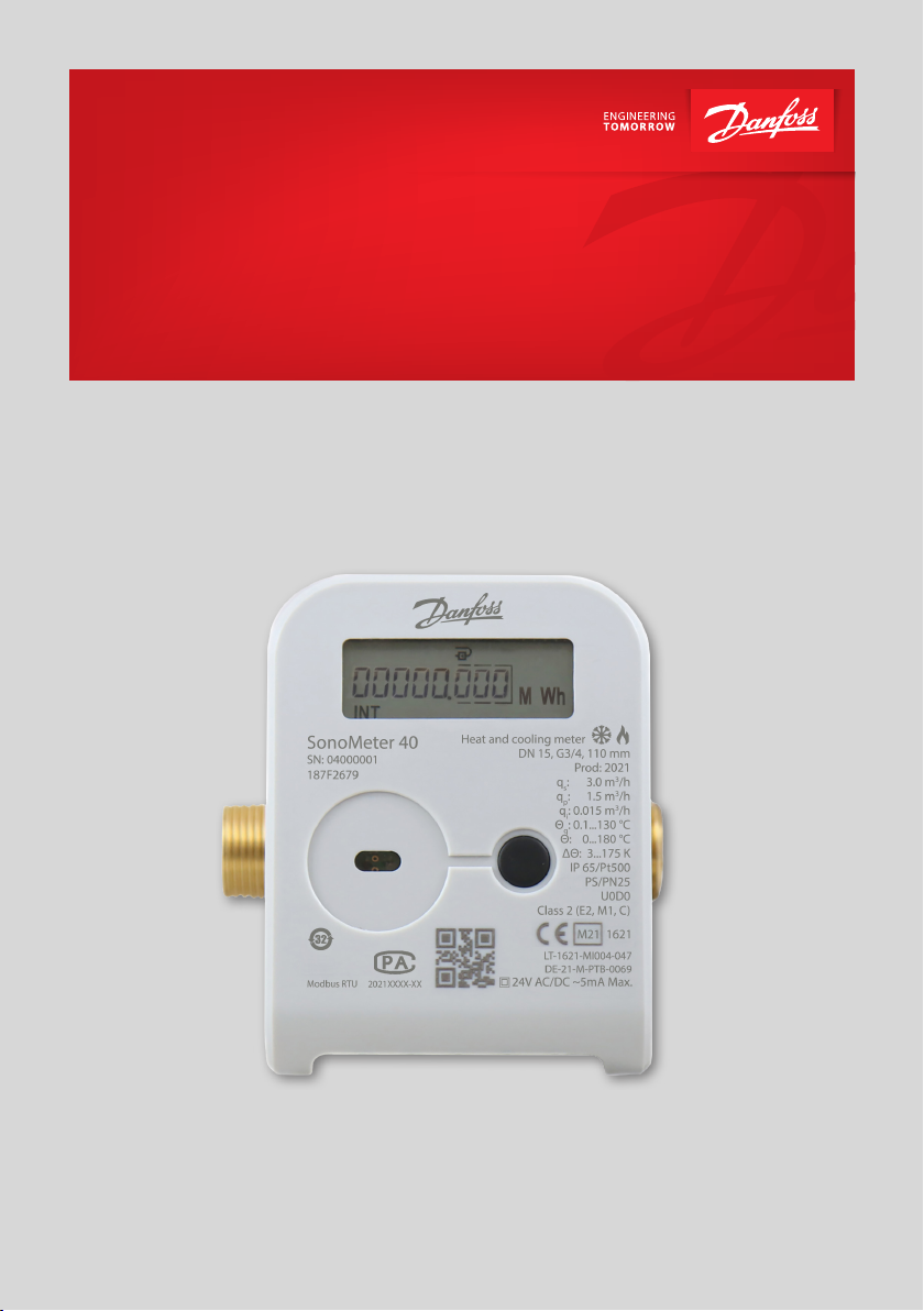
SonoMeter 40
Ultrasonic energy meter
for heating and cooling applications
www.danfoss.com
This doc. is managed by 500B0577
1
of
2
Installation guide SonoMeter 40
EU DECLARATION OF CONFORMITY
Danfoss A/S
6430 Nordborg, Denmark | CVR nr.: 20 16 57 15 | Telephone: +45 7488 2222 | Fax: +45 7449 0949
declares under our sole responsibility that the
Product category: Energy Meters Type designation(s): SonoMeter 40
Covered by this declaration is in conformity with the following directive( s), standard(s) or other normative
document(s), provided that the product is used in accorda
[RED] – Radio Equipment Directive 2014/53/EU
Article 3.1a (LVD)
EN 61010-1:2010+A1:2019
EN 62368-1:2014
EN 62311: 2008
Article 3.1b (EMC)
EN 301 489-3 V2.1.1
EN 301 489-1 V1.9.2
Article 3.2 (Radio)
EN 300 220-1 V3.1.1
EN 300 220-2 V3.1.1
[EMC] – Electromagnetic Compatibility Directive 2014/30/EU
EN 55032:2015+A11:2020
[LVD] – Low Voltage Directive 2014/35/EU
EN 61010-1:2010+A1:2019
EN 62368-1:2014
EN 62311: 2008
[MID] – Measuring Instruments Directive 2014/32/EU
EN 1434-1:2015+A1:2018
EN 1434-2:2015+A1:2018
EN 1434-3:2015
EN 1434-4:2015+A1:2018
EN 1434-5:2015+A1:2019
EN 1434-6:2015+A1:2019
WELMEC 7.2:2015 - Software Guide
Noti�ied Body: Lithuanian Energy Institute, 1621, performed type approval and issued certi�icate LT-1621-MI004-047.
[RoHS] – Restriction of Hazardous Substances Directive 2011/65/EU+A:2015/863
EN IEC 63000:2018
Danfoss Energy Metering
nce with our instructions.
2
1
1, 3
4
1 For variants with Radio Module the declaration for EMC & LVD shall be ignor ed
2 For variants without Radio Module the declaration for RED shall be ignored.
3 For variants without Radio Module and without Mains power supply (24V AC /DC) the declaration for RED and LVD shall be ignored.
4 Not within MID – National Type Approval Certi�icate for cooling energy DE-21- M-PTB-0069 is issued by “Physikalisch-T
Date:
2021.09.22
Place of issue:
8811 Scheifling
Austria
Danfoss only vouches for the correctness of the English version of this declaration. In the event of the declaration being translated into any other
language, the translator concerned shall be liable for the correctness of the translation
ID No: 014R2944
Issued by Date:
Signature:
Name: Norbert Spreitzer
Title: Product Portfolio Manager
Revision No: 01
2021.09.22
Place of issue:
1210 Ljubljana,
Slovenia
Approved by
Signature:
Name: Gasper Benedik
Title: Energy Meters Director
echnische Bundesanstalt”.
Page
2 | © Danfoss | Energy Meters | 2021.10 AN384648824392en-010102
This doc. is managed by 500B0577
2
of
2
Installation guide SonoMeter 40
UK DECLARATION OF CONFORMITY
Danfoss A/S
6430 Nordborg, Denmark | CVR nr.: 20 16 57 15 | Telephone: +45 7488 2222 | Fax: +45 7449 0949
declares under our sole responsibility that the
Product category: Energy Meters Type designation(s): SonoMeter 40
Covered by this declaration is in conformity with the following directive( s), regulation(s), standard(s) or other
normative document(s), provided that the product
Radio Equipment Regulations 2017
Article 3.1a (LVD)
BS EN 61010-1:2010+A1:2019
BS EN 62368-1:2014
BS EN 62311:2008
Article 3.1b (EMC)
EN 301 489-3 V2.1.1
EN 301 489-1 V1.9.2
Article 3.2 (Radio)
EN 300 220-1 V3.1.1
EN 300 220-2 V3.1.1
Electromagnetic Compatibility Regulations 2016
BS EN 55032:2015+A11:2020
Electrical Equipment (Safety) Regulations 2016
BS EN 61010-1:2010+A1:2019
BS EN 62368-1:2014
BS EN 62311:2008
Danfoss Energy Metering
is used in accordance with our instructions.
2
1
1, 3
The Restriction of the Use of Certain Hazardous Substances in Electrical and Electronic Equipment Regulations 2012
(as amended)
BS EN IEC 63000:2018
Heat Metering and Billing Regulations 2014
Heat meter accuracy cl. 7.9:
Noti�ied Body: Lithuanian Energy Institute, 1621, performed type approval and issued certi�icate LT-1621-MI004-047.
1 For variants with Radio Module the declaration for EMC & LVD shall be ignor ed
2 For variants without Radio Module the declaration for RED shall be ignored.
3 For variants without Radio Module and without Mains power supply (24V AC /DC) the declaration for RED and LVD shal
Date:
2021.09.22
Place of issue:
8811 Scheifling
Austria
Danfoss only vouches for the correctness of the English version of this declaration. In the event of the declaration being translated into any other
language, the translator concerned shall be liable for the correctness of the translation
ID No: 014R2944
Issued by Date:
Signature:
Name: Norbert Spreitzer
Title: Product Portfolio Manager
Revision No: 01
2021.09.22
Place of issue:
1210 Ljubljana,
Slovenia
Approved by
Signature:
Name: Gasper Benedik
Title: Energy Meters Director
l be ignored.
Page
AN384648824392en-010102 © Danfoss | Energy Meters | 2021.10 | 3
Installation guide SonoMeter 40
1. Installation
1.1. Preparation
Only qualified personnel may install the equipment, following the requirements listed in this document.
More detailed instruction can be found on www.heating.danfoss.com.
Note! This product is approved for ambient temperature between 5-55° C, but to ensure optimal conditions for
battery it is recommended to install Calculator at max. 45° C. Avoid installation stress from pipes and fittings.
Flush the system.
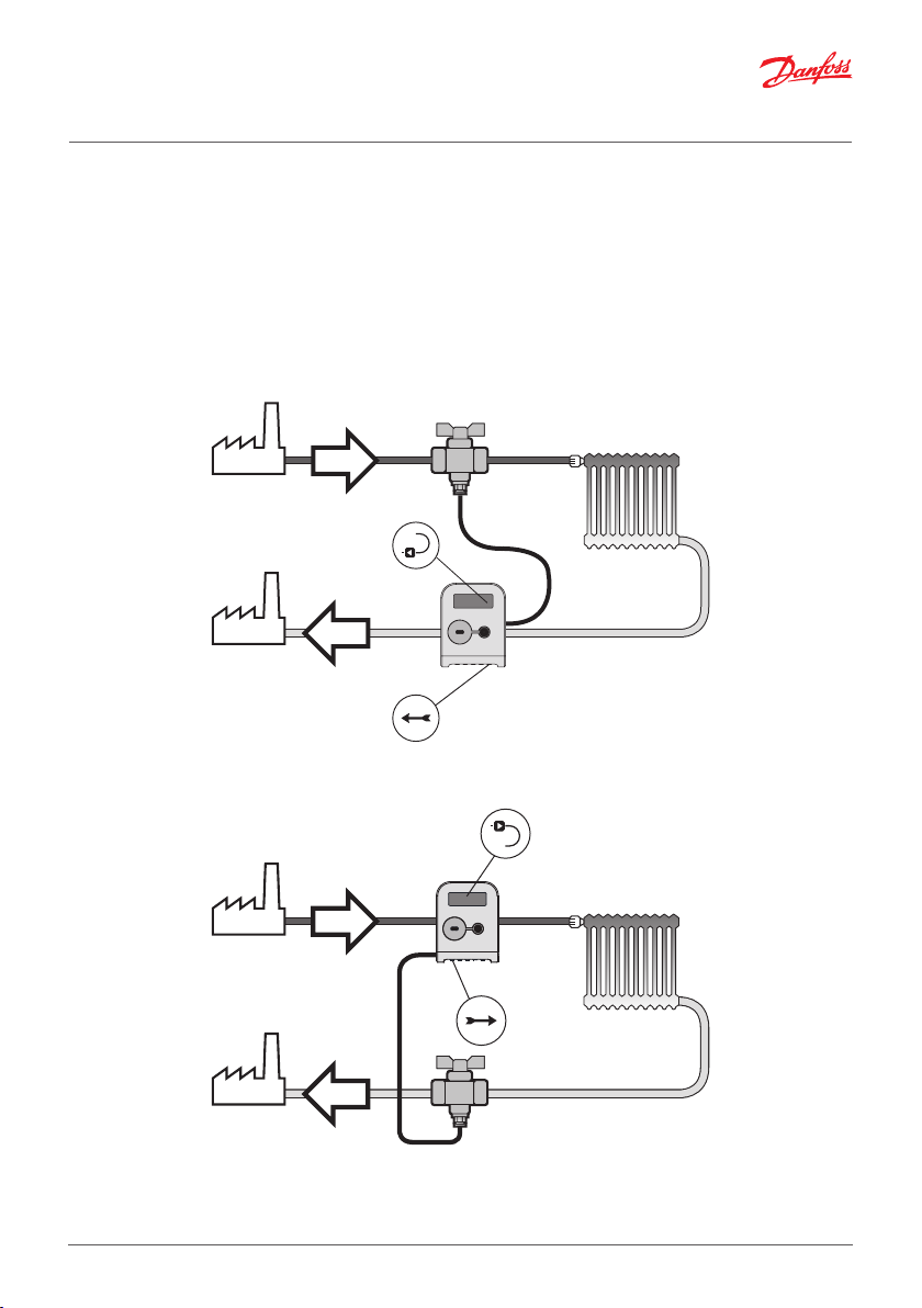
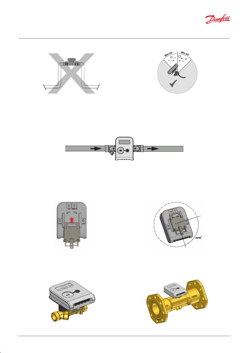
1.2. Identification of installation: Return/Supply pipe installation and flow direction
Flow direction
Return pipe installation
Flow direction
Supply pipe installation
AN384648824392en-010102 © Danfoss | Energy Meters | 2021.10 | 4
Installation guide SonoMeter 40
1.3. Mounting of flow sensor
Pipe position: No limitations but avoid positions
where air can be collected.
Rotation in pipe axis: Flow sensor should be angled
in 45 to 315° to avoid air collection in flow sensor.
Inlet/outlet conditions (only for DN 65-DN 100)
In order to maximize performance it is necessary to have straight inlet and outlet flow conditions before
and after the flow sensor: 5 × DN on inlet and 3 × DN on outlet of flow sensor.
5 x DN 3 x DN
flow
1.4. Mounting and sealing of calculator
Heat meter calculator may be installed in heated premises, working ambient temperature shall
be not more than 55 °C. It may not be exposed to direct sunlight.
The calculator is mounted on an auxiliary holder (it can be oriented in the required direction at an angle of
each 90 °:
The possible ways of the mounting of the calculator (auxiliary holder):
- Direct mounting on the housing of the flow sensor, by turning each 90o (only when the flow temperature
does not exceed 90oC):
5 | © Danfoss | Energy Meters | 2021.10 AN384648824392en-010102

Installation guide SonoMeter 40
- On the wall:
- Panel mounting on standard DIN-rail.
Important: It is prohibited to attach the electronic unit directly on the wall because there is a risk
that moisture may condense on the walls of the room or the temperature of the surface of the wall may
drop below 5 °C. In this case, it is recommended to mount the electronic unit so that to provide for an air
space of at least 5 cm between the unit and the wall surface.
Calculator seals
For design with permanently connected temperature sensors no additional sealing applies to the
electronic unit of a newly manufactured heat meter. Access to elements fixing the opening of the box,
configuration change activation contacts, and adjustment data change activation contacts is protected
by special easily breakable partitions.
a) b) c)
Access to elements fixing the opening of the box (a), configuration change activation contacts (b) and
adjustment data change activation contacts (c) (partitions easily breakable with a tool)
AN384648824392en-010102 © Danfoss | Energy Meters | 2021.10 | 6

Installation guide SonoMeter 40
Seal
Seal
After the opening of the box, change of the configuration, or adjustment of the meter (when the special
partitions were broken out for this purpose), the opened slots must be additionally sealed with sticker
seals:
- the two slots marked LOCK for access to the elements fixing the opening of the box are sealed with
test sticker seals (Fig. 4.1a),
- the slot marked SERVICE for access to the configuration change activation contacts is sealed with
the supplier’s sticker seal (Fig. 4.1b),
- the slot marked ADJ for access to the adjustment data change activation contacts is sealed with the
supplier’s sticker seal (Fig. 4.1c).
For design with changeable temperature sensors (IP65 protection class of the calculator only!) the
inspection seals /adhesive seals protect the access to protective cap mounting bolt and to adjustment data
change activation contacts ADJ, if breakable partition is broken out.
The inspection seals /adhesive seals protect the access to protective cap mounting bolt (1) and to
adjusment data change activation contacts (2) , if breakable partition is broken out.
1.5. Mounting and sealing of temperature sensors
Installation recommendations for
ball valve mounting and sealing
7 | © Danfoss | Energy Meters | 2021.10 AN384648824392en-010102
Installation recommendations for
direct short temperature sensors

Installation guide SonoMeter 40
Seal
ocket
Seal
Pocket
a) angled 45°
Installation recommendations for pocket temperature sensors with permanently connected signal leads.
b) perpendicular
P
2. Electrical wiring
2.1 Connection of a meter with permanently connected temperature sensors (IP 67/68)
The meter version with permanently connected temperature sensors is fully ready for installation,
complete with the necessary cables for connection (no need to open the meter).
If the meter is equipped with wired interfaces or a pulse input / output function, appropriate and marked
cables to connect the relevant external device are provided.
If the meter is intended to be powered by an external source of 230V AC or 24V AC / DC, the dedicated
and marked cable of the meter shall be connected to the appropriate source.
2.2 Connection of the meter with changeable temperature sensors (IP65)
If the meter is fully assembled (temperature sensors are connected, communication interface cables are
in place) - follow the installation procedure in p.5.3.1 (the meter does not need to be opened). Otherwise,
it is necessary to open the electronic unit box.
Opening of electronic unit box
Before opening the electronic box, make sure that the meter version is with changeable temperature
sensors:
Check!
IP65 = Openable Version (with exchangeable
temperature sensors)
IP67 = Not openable
IP68 = Not openable
8 | © Danfoss | Energy Meters | 2021.10 AN384648824392en-010102

Installation guide SonoMeter 40
Wiring diagram 1
Design with changeable
temperature sensors, Mbus1
interface. Meter power supply from
a battery.
Wiring diagram 2
Design with changeable
temperature sensors, additional
interface module
(additional interface module
mounting bracket under the
module). Meter power supply from
a battery.
9 | © Danfoss | Energy Meters | 2021.10 AN384648824392en-010102
Installation guide SonoMeter 40
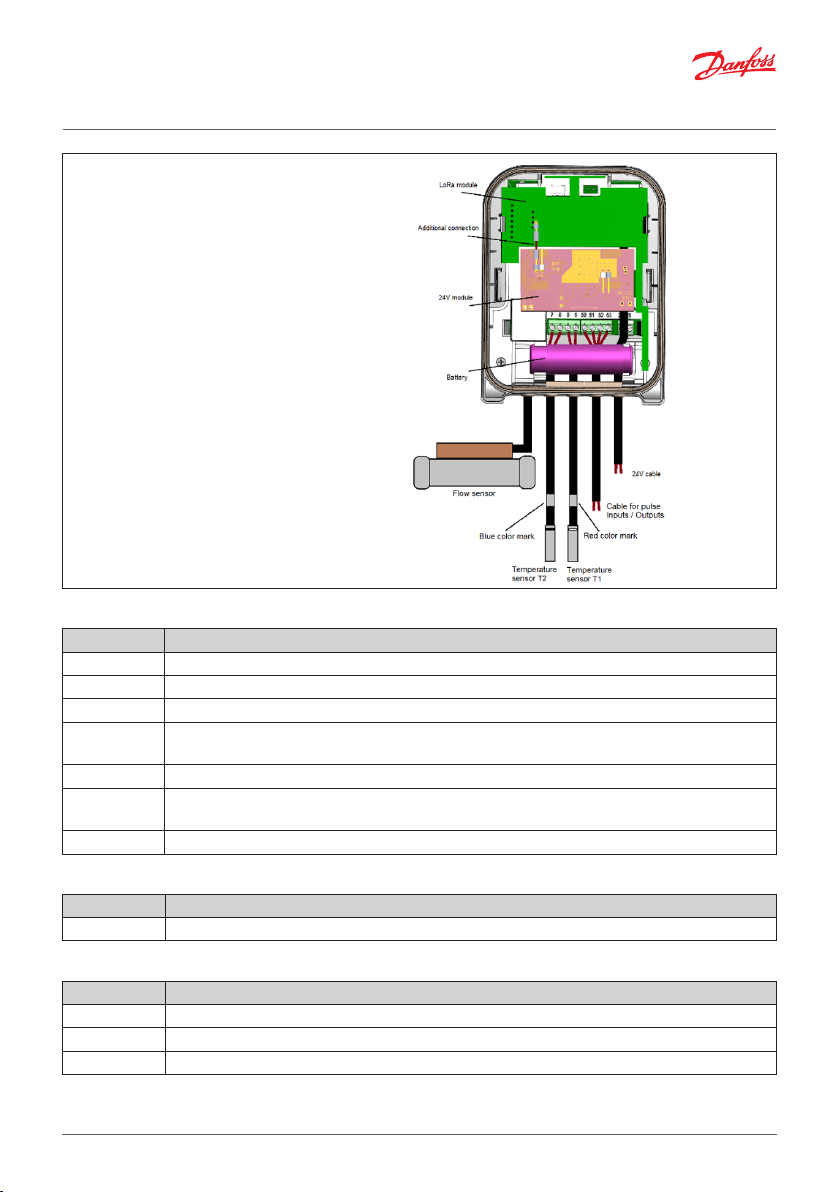
Wiring diagram 3
Design with changeable
temperature sensors, LoRa interface
and 24V power supply module.
The 24V power supply module is
mounted on the battery holder and
connected to the B1 connector of
the meter.
A backup battery is connected to
the BAT connector of the module.
The 24V power cable is connected
to the “24V” terminals of the
module (connections are made
before mounting the module, as
the connectors and terminals are
on the other side of the module).
The LoRa interface module is
connected to the 24V power supply
module connector by an additional
connection cable.
Numbering of calculator terminals
Terminal N. Description
5, 6 High temperature sensor (T1)
7, 8 Low temperature sensor (T2)
50 Common terminal for 2nd additional pulse input/output (GND)
51
52 Common terminal for 1st additional pulse input/output (GND)
53
24, 25 M-bus data lines (bipolar)
2nd additional pulse input/output (In/Out2)
(Volume output for TEST mode)
1st additional pulse input/output (In/Out1)
(Energy output for TEST mode)
Numbering of M-bus communication module terminals
Terminal N. Description
24, 25 M-bus module (bipolar)
Numbering of MODBUS and BACnet communication module terminals
Terminal N. Description
60, 61 12-24 V DC power supply voltage for MODBUS and BACnet (bipolar)
90 MODBUS or BACnet Line +
91 MODBUS or BACnet Line -
10 | © Danfoss | Energy Meters | 2021.10 AN384648824392en-010102

Installation guide SonoMeter 40
3. Commissioning
3.1. Bleeding
1. Bleed the system until the flow rate display is steady.
2. Make sure no error codes are displayed.
3. Check the display for a plausible indication of flow rate and temperatures.
3.2. IP class
Calculator IP65 (IP68 on special request)
Flow sensor IP68
4. Display function overview
4.1. Menu structure
INT
Integral parameters
BIL
Statistical data
INF
Informative parameters
1.1 1.2 1.3 1.4 1.51.6 1.7
2.1 2.2 2.3 2.4 2.52.6.1 2.7.12xx 2.15.1
3.1 3.2 3.3 3.4 3.5
3.6.13.7 3x 3.15
1.8
1.9
4.2. Display symbols
Explanation of special symbols:
flow is flowing forward (right direction)
flow is flowing backwards (wrong direction)
no arrow
no flow
Explanation of other symbols are described in detailed instruction on www.heating.danfoss.com.
4.3. Error codes
Long press
Shift down
Short press
Shift to the right
11 | © Danfoss | Energy Meters | 2021.10 AN384648824392en-010102

Installation guide SonoMeter 40
Errors are encoded by a 4-digit code.
Code Description
Status of calculator
Status of the return heat carrier temperature sensor (T2)
0 - normal operation
1 - battery service life has expired (or the meter was not power supplied –
if it is externally power supplied)
2 - temperature differential is higher than permissible limits
4 - temperature differential is lower than permissible limits
8 - electronic unit hardware failure *
0 - normal operation
4 - the sensor is short-circuited *
8 - the sensor is disconnected or short-circuited *
Status of the supply heat carrier temperature sensor (T1)
Status of flow sensor 0 - normal operation
* - only in case of these serious errors will be stopped the summation of energy and normal working time, the
error code will be displayed on the LCD first page, additionally the error date will be displayed.
Error codes sum up if there are more than one error. Then the summary indicated error code will be as
follows:
• 3 – corresponds to error codes 2 + 1
• 5 – corresponds to error codes 4 + 1
• 7 – corresponds to error codes 4 + 2 + 1
• 9 – corresponds to error codes 8 + 1
• A – corresponds to error codes 8 + 2
• B – corresponds to error codes 8 + 2 + 1
• C – corresponds to error codes 8 + 4
• D – corresponds to error codes 8 + 4 + 1
• E – corresponds to error codes 8 + 4 + 2
• F – corresponds to error codes 8 + 4 + 2 + 1
If at least one digit value of an error code is ≥8, the summing-up of energy, water quantity, and trouble-free
operation time is stopped.
In case of the flow sensor error 4, the time “when the flow q> 1.2∙qs” is recorded additionally.
0 - normal operation
4 - the sensor is short-circuited *
8 - the sensor is disconnected or short-circuited *
1 – no signal; the flow sensor is not filled with water
2 – reverse flow
4 – the flow is greater than 1.2∙qs (indicated q=1.2∙qs)
8 – hardware failure *
12 | © Danfoss | Energy Meters | 2021.10 AN384648824392en-010102

Installation guide SonoMeter 40
5. Disposal
This symbol on the product indicates that it may not be disposed of as household
waste.
It must be handed over to the applicable take-back scheme for the recycling of
electrical and electronic equipment.
• Dispose of the product through channels provided for this purpose.
• Comply with all local and currently applicable laws and regulations.
Item Material Disposal
Battery
PCBA with display
Cables Copper with PUR or PVC jackets Cable recovery
Flow sensor (incl. trans-
ducer and liner)
Transducer PZT, stainless steel, PEI Approved deposit for PZT
Other plastic parts PC, PPS, PEI, TPE Plastic recovery
AA-cell lithium/thionyl chloride 700 mg
lithium
Coppered epoxy laminate components
soldered on, PC, TPE
Brass, stainless steel, PPS Metal recovery
Approved deposit for lithium
batteries
Electronic waste
6. Local Importer name and address
For goods delivered to UK, importer name and address is:
Danfoss Ltd.
22 Wycombe End
HP9 1NB
GB
AN384648824392en-010102 © Danfoss | Energy Meters | 2021.10 | 13

Installation guide SonoMeter 40
14 | © Danfoss | Energy Meters | 2021.10 AN384648824392en-010102

Installation guide SonoMeter 40
15 | © Danfoss | Energy Meters | 2021.10 AN384648824392en-010102

16 | © Danfoss | Energy Meters | 2021.10 AN384648824392en-010102
 Loading...