

Page 1
User Guide
User Guide
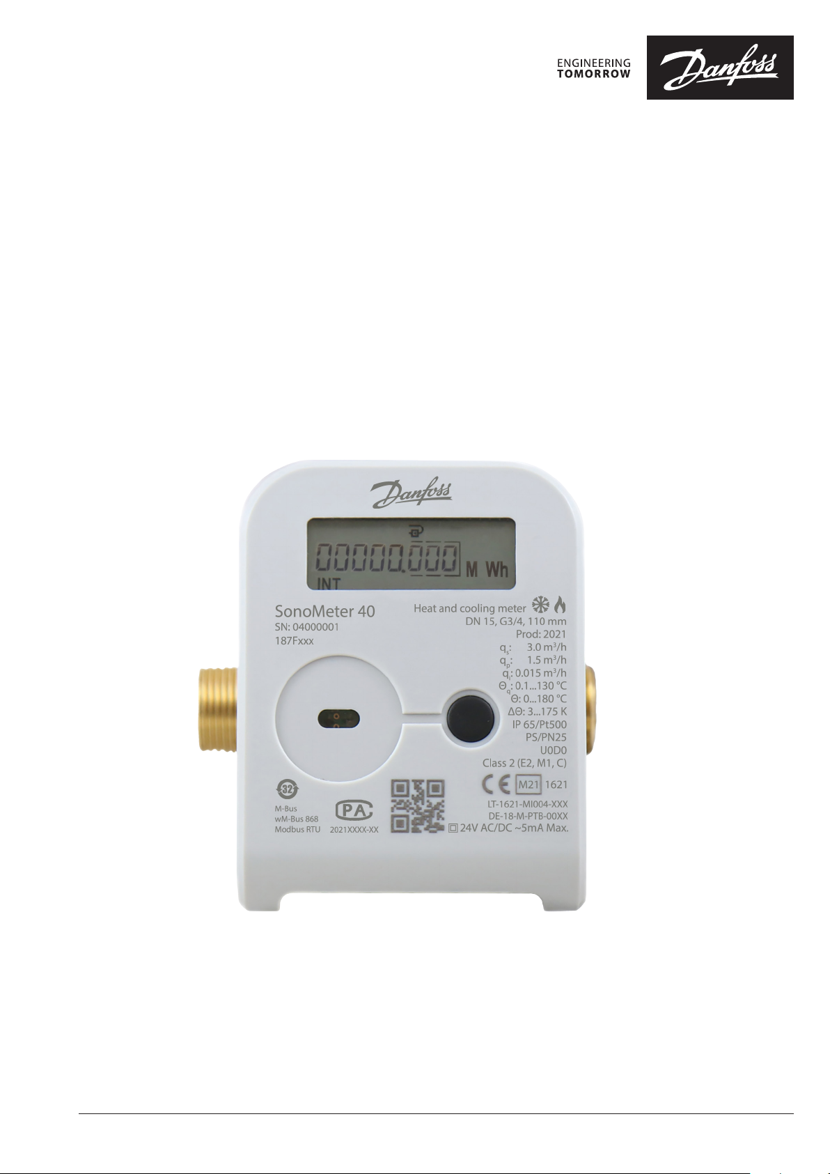
SonoMeter 40
Ultrasonic energy meter SonoMeter 40
Ultrasonic energy meter
Test and calibration instruction
for heating and cooling applications
© Danfoss | Energy Meters | 2021.09 BC389148615526en-010101 | 1
Page 2

User Guide SonoMeter 40
Contents
General information ..............................................................................................................................3
1. Activation of the test mode .............................................................................................................. 3
1.1 Activation of the test mode with the button ...............................................................................................................3
1.2 Activation of the test mode by short-circuiting the contacts ................................................................................. 4
1.3 Activation of test mode with software “SonoMeter 40 Configurator”..................................................................5
2. Determination of measurement errors of the meter ......................................................................6
2.1 Volume measuring errors determination test ............................................................................................................. 6
2.2 Energy measurement errors determination test ........................................................................................................6
3. Turn off the test mode ..................................................................................................................... 14
4. Meter calibration/adjustment mode ............................................................................................. 14
2 | BC389148615526en-010101 © Danfoss | Energy Meters | 2021.09
Page 3
User Guide SonoMeter 40
General information
1. Activation of the test
mode
1.1. Activation of the test
mode with the button
This instruction is designed for the ultrasonic energy meter SonoMeter 40 for flow and energy
verification and calibration.
The test mode can be activated in one of the following ways:
The test mode is activated by the meter’s control button according to the following procedure:
- long press the button, on the meter’s LCD select page „INF“;
- short press the button, select „TEST on Wh“ (when it is necessary to activate the energy pulse
output via the optical interface) or „TEST On m³“ (when it is necessary to activate the volume pulse
output via the optical interface);
- long press the button, open the 4- digits security password input window:
- short press the button, select digit in the first position, after that long press the button and go to
the next position;
- after selecting the digit in the fourth position, long press the button, the massage „PASS“ appears
briefly (when the password entered correctly) and the meter switches to test mode – the sign
„TEST“ appears;
- if the password was entered incorrectly, the message „FAIL“ appears briefly and the meter returns
to the operating mode, and the procedure for turning on the test mode must be repeated initially;
- the password value is fixed: 0001.
NOTE: when the test mode is activated by the button, the volume and energy accumulated in
the test mode are added to the meter’s energy and volume readings in operating mode (after
turning off the test mode).
1.2. Activation of the test
mode by short-circuiting
the contacts
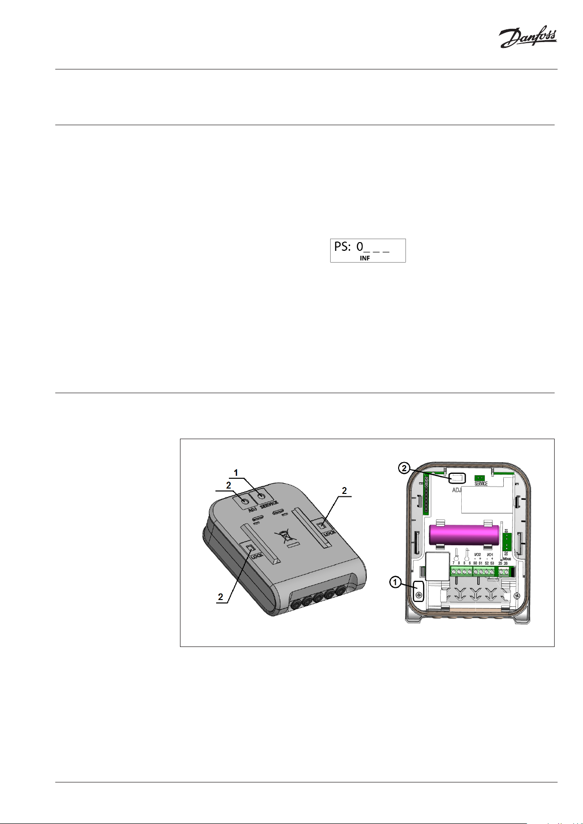
Remove the breakable partition „SERVICE” (1) on the back of the calculator or open the calculator box
by removing the breakable partitions “LOCK” (2).
By short-circuiting the contacts „SERVICE”, the SERVICE mode is activated, symbol „<->“ and sign
„TEST” are displayed on the LCD.
BC389148615526en-010101 | 3© Danfoss | Energy Meters | 2021.09
Page 4

User Guide SonoMeter 40
1.2. Activation of the test
mode by short-circuiting
the contacts (continuous)
Display readings in the test mode
ID Parameter Value Notes
4.1 High- resolution energy
TEST
000000.00 Wh
TEST
PULSE
TEST m
Updated every second.
Indicated as “PULSE”, if the energy
test pulse output is activated.
3
Updated every second.
00.000000
4.2 High-resolution integrated volume
Supply heat carrier temperature
4.3
value
Return heat carrier temperature
4.4
value
4.5 Temperature difference
4.6 High-resolution flow rate
TEST m
PULSE
1 TEST
0.0 °C
2 TEST
0.0 °C
1-2 TE ST
0.00 °C
TEST m
0.000
Indicated as “PULSE m³”, if the
3
volume test pulse output is
activated.
-
-
-
3
-
INF
To activate energy pulses output
(when volume pulse output is active)
4.7
To activate volume pulse output
(when energy pulse output is active)
4.8 To deactivate the test mode
TEST
tESt on Wh
TEST m3
tESt on
TEST
tESt OFF
Activated by pressing and holding
the button
Activated by pressing and holding
the button
Deactivated by pressing and holding
the button
In this mode:
- volume pulses are generated via the optical interface of the meter. The button can be used to
toggle the energy pulse output by selecting the menu item "tEST on Wh”;
- When the meter is supplied with a connected pulse input/output cable , the energy pulses are
generated in the 1st pulse output and the volume pulses in the 2nd pulse output;
- it is possible to simulate volume pulses for determination the energy measurement errors;
- it is possible to change the parameters of the meter configuration.
NOTE: when the test mode is activated by short-circuiting the contacts “SERVICE”, the volume
and energy accumulated in the test mode are not added to the meter’s operating mode
volume and energy readings.
4 | BC389148615526en-010101 © Danfoss | Energy Meters | 2021.09
Page 5

User Guide SonoMeter 40
1.3. Activation of test
mode with software
“SonoMeter 40
Configurator”
The test mode can be activated via the optical interface using the software “SonoMeter 40
Configurator” and optical scan head in accordance with EN 62056-21 standard. In this case, optionally
volume or energy pulses are generated via the optical interface of the meter.
ON TEST (E Pulse) mode – intended for test (TEST) mode activation (with energy pulse output via
optic interface).
ON TEST (V Pulse) mode – intended for test (TEST) mode activation (with volume pulse output via
optic interface).
OFF TEST mode – intended for deactivation of the test (TEST) mode.
Start E-test – intended for energy measurement stimulating volume for 150 sec operations (only in
the Service mode).
BC389148615526en-010101 | 5© Danfoss | Energy Meters | 2021.09
Page 6

User Guide SonoMeter 40
2. Determination of
measurement errors of
the meter
2.1. Volume measuring
errors determination test
2.2. Energy measurement
errors determination test
The determination of volume measurement errors shall be carried out in the hydrodynamic test
bench in the following order:
1) The test mode is activated in accordance with section 1.1, 1.2, or 1.3 of this instruction.
2) The volume measuring errors should be evaluated at control flow rates specified in EN1434-5.
3) The volume of water, passing through the meter can be read directly from the indicating device
(with resolution 1 ml);
- Via meter optical output, using the optical reading head according to 62056-21;
- Or trough wired volume pulse 2nd output (for a complete meter with a connected pulse input /
output cable and for a meter activated in test mode according to p.1.2 of this instruction);
4) Volume pulse values in test mode are presented in table 1p:
Tab le 1p
Permanent flow-rate qp of the heat meter, m³/h Volume pulse value in test mode, litre/pulse
0,6 and 1,0 0,002
1,5 0,004
2,5 0,005
3,5 and 6 0,02
10; 15 and 25 0,05
40 and 60 0,2
The energy measurement error of a calculator with temperature sensors pair shall be evaluated by
immersing the temperature sensors in a temperature regulated baths. The test shall be performed in
the following order:
1) The test mode is activated in accordance with section 1.2 of this instruction;
2) The meter temperature sensors are immersed in thermostatic baths, which form the supply and
return line temperature and temperature difference values specified in EN 1434-5.
NOTE: energy measurement error determination may be performed separately for a calculator with
a flow sensor. In this case, the temperature and temperature differences of the supply and return line
specified in EN 1434-5 are simulated by connecting the reference resistors to the calculator terminals
No.5;6;7;8.
3) Long press the button (for more than 5 seconds) activates the simulation of the volume pulses (the
meter display periodically shows "SF" with the nominal flow rate of the meter, m³/h):
4) After 2,5 min. the volume simulation is completed, the sign „SF“ turns off. To calculate the energy
measurement error, the simulated volume and energy readings shall be visually read from the
meter display;
5) The amount of volume or energy can be read through the wired pulse output (if it is equipped in
the meter);
6) The amount of volume or energy can be read through the meter's optical interface output using an
optical scan head that complies with EN 62056-21;
7) Energy pulse values in test mode are presented in table 2p:
Tab le 2p
Permanent flow-rate qp
of the heat meter, m³/h
0,6 and 1,0 0,1 Wh/pulse 0,5 kJ/ pulse 0,1 kcal/ pulse
1,5 0,2 Wh/ pulse 1 kJ/ pulse 0,2 kcal/ pulse
2,5 0,5 Wh/ pulse 2 kJ/ pulse 0,5 kcal/ pulse
3,5 and 6 1 Wh/ pulse 5 kJ/ pulse 1 kcal/ pulse
10; 15 and 25 2 Wh/ pulse 10 kJ/ pulse 2 kcal/ pulse
40 and 60 5 Wh/ pulse 20 kJ/ pulse 5 kcal/ pulse
0,6 and 1,0 10 Wh/ pulse 50 kJ/ pulse 10 kcal/ pulse
„kWh“, „MWh“ „GJ“ „Gcal“
Energy pulse value based on displayed energy units:
6 | BC389148615526en-010101 © Danfoss | Energy Meters | 2021.09
Page 7

User Guide SonoMeter 40
3. Turn off the test mode
4. Meter calibration/
adjustment mode
The test mode can be turned off in one of the following ways:
- long press the button selects page „INF“ on the meter’s LCD short presses the button selects
„tEST off“ on the LCD long press the button and the test mode is turn off, there is no sign „TEST“
on the screen (when the test mode is activated in accordance with section 1.1 of this instruction);
- by short-circuiting the contacts “SERVICE”, (when the test mode is activated in accordance with
section 1.2 of this instruction);
- via the optical interface, using the software “SonoMeter 40 Configurator” and optical head that
complies with EN 62056-21 standard (when the test mode is activated in accordance with section
1.1 or 1.3 of this instruction);
NOTE: the meter switches to the operating mode by itself 12 hours after activation the test
mode.
Meter calibration/adjustment allows to adjust the meter measurement of volume single point
characteristics.
It can be done by using the software “SonoMeter 40 Configurator” and optical scan head in
accordance with EN 62056-21 standard.
1) The calibration/adjustment mode can be activated by removing protecting lid (2) of ADJ and
shortcutting the pins.
2) The correction parameter for volume can be entered in the SonoMeter 40 Configurator fields
“Err[%]”. The correction parameter is confirmed by clicking “Calculate”. “Write configuration” stores
the adjustments into the meter permanent memory. “Read configuration” is used to verify that the
changes are stored.
NOTE: With the removed ADJ protective cover. The Manufacturer warranty is void!!!
BC389148615526en-010101 | 7© Danfoss | Energy Meters | 2021.09
Page 8

User Guide SonoMeter 40
4. Meter calibration/
adjustment mode
(continuous)
RESET Integrators and Loggers – intended to reset the integrator and logger values to a zero.
RESET Battery time – intended to reset the battery lifetime after replacement (the new battery
replacement date will be calculated according to the set Battery lifetime value).
OFF ADJ mode – intended for deactivation of the Adjustment mode.
© Danfoss | Energy Meters | 2021.098 | BC389148615526en-010101
 Loading...