


Installation & User Guide
SonoMeter 31
Ultrasonic energy meter
for heating and cooling applications
www.danfoss.com

Installation & User Guide SonoMeter 31
2 | © Danfoss | DHS-SRMT / PL | 2018.08 VI.SH.O2.02

Installation & User Guide SonoMeter 31
1. Installation
1.1. Preparation
Only qualified personnel may install the equipment, following the requirements listed in this document.
More detailed instruction can be found on www.heating.danfoss.com.
Note! This product is approved for ambient temperature between 5-55° C, but to ensure optimal conditions for
battery it is recommended to install Calculator at max. 45° C. Avoid installation stress from pipes and fittings.
Flush the system.
1.2. Identification of installation: Return/Supply pipe installation and flow direction
Flow direction
Return pipe installation
Flow direction
Supply pipe installation
VI.SH.O2.02 © Danfoss | DHS-SRMT / PL | 2018.08 | 3

Installation & User Guide SonoMeter 31
1.3. Mounting of flow sensor
Pipe position: Avoid positions where
air can be collected.
Rotation in pipe axis: Flow sensor should be angled
in 45 to 315° to avoid air collection in flow sensor.
Inlet/outlet conditions
In order to maximize performance it is necessary to have straight inlet and outlet flow conditions before
and after the flow sensor: 5 × DN on inlet and 3 × DN on outlet of flow sensor.
5 × DN
flow
3 × DN
1.4. Mounting and sealing of calculator
On the wall: Panel mounting on standard DIN-rail:
4 | © Danfoss | DHS-SRMT / PL | 2018.08 VI.SH.O2.02

Installation & User Guide SonoMeter 31
Seal
ocket
1.5. Mounting and sealing of temperature sensors
Seal
Pocket
a) angled 45°
Installation recommendations for pocket temperature sensors with permanently connected signal leads.
b) perpendicular
P
2. Electrical wiring
Electrical wiring diagram with 2-wire temperature sensors for DN65, DN80 and DN100
V1…V2 – ultrasonic flow sensors
T1…T3 – temperature sensors
V3…V4 – water meters with pulse output
p1…p2 – pressure sensors
Remark: Only required for selected meter type is connected
VI.SH.O2.02 © Danfoss | DHS-SRMT / PL | 2018.08 | 5

Installation & User Guide SonoMeter 31
Electrical wiring diagram with 2-wire temperature sensors for smaller sizes (DN15 -DN50)
*
*
*
*
* optional*
V1…V2 – ultrasonic flow sensors
T1…T3 – temperature sensors
V3…V4 – water meters with pulse output
p1…p2 – pressure sensors
Remark: Only required for selected meter type is connected
6 | © Danfoss | DHS-SRMT / PL | 2018.08 VI.SH.O2.02
*

Installation & User Guide SonoMeter 31
Calculator
Terminals Marking Description
60 V1-1 (+) Output signal (OUT) from 1st flow sensor V1
61 V1-1(−) GND for output (OUT) of 1st flow sensor V1
62 V1-2 (+) Input signal (IN) from 1st flow sensor V1
63 V1-2 (−) GND for input (IN) of 1st flow sensor V1
64 V2-1 (+) Output signal (OUT) from 2nd flow sensor V2
65 V2-1 (−) GND for output (OUT) of 2nd flow sensor V2
66 V2-2 (+) Input signal (IN) from 2nd flow sensor V2
67 V2-2 (−) GND for input (IN) of 2nd flow sensor V2
1* T1 Current terminal for 1-st temperature sensor “+I”
5 T1 Voltage terminal for 1-st temperature sensor “+U”
6 T1 Voltage terminal for 1-st temperature sensor “−U”
2* T1 Current terminal for 1-st temperature sensor “−I”
50* GND for temperature sensors
3* T2 Current terminal for 2-nd temperature sensor “+I”
7 T2 Voltage terminal for 2-nd temperature sensor “+U”
8 T2 Voltage terminal for 2-nd temperature sensor “−U”
4* T2 Current terminal for 2-nd temperature sensor “−I”
9 + +3,6V power supply voltage for pulse inputs V3, V4
53 V3 Pulse input signal from 1-st input V3 (IN)
11 GND for V3 and V4 pulse inputs
54 V4 Pulse input signal from 2-nd input V4 (IN)
56* T3 Current terminal for 3-rd temperature sensor “+I”
57 T3 Voltage terminal for 3-rd temperature sensor “+U”
58 T3 Voltage terminal for 3-rd temperature sensor “−U”
59* T3 Current terminal for 3-rd temperature sensor “−I”
82 GND for pressure sensor р1
68 P1 Input signal from 1-st pressure sensor (IN)
51 + +18 V power supply voltage for pressure sensors p1, p2
83 GND for pressure sensor р2
69 P2 Input signal from 2-nd pressure sensor (IN)
7 | © Danfoss | DHS-SRMT / PL | 2018.08 VI.SH.O2.02

Installation & User Guide SonoMeter 31
REMARK: * – only for 4-wire connection method of temperature sensors (K)
Communication modules
Terminal
number
76 GND for currency outputs
77 Iout1 1st currency outputs (+)
78 Iout2 2nd currency outputs (+)
79 GND for pulse outputs
80 Puls 1 1st pulse outputs (+)
81 Puls 2 2nd pulse outputs (+)
24 (73) BUS M-bus line L1
25 (74) BUS M-bus line L2
75 BUS GND for communication interface RS-232
60 60 MODBUS module 12–24 V DC power terminal (bipolar)
61 61 MODBUS module 12–24 V DC power terminal (bipolar)
90 90 MODBUS module line (+)
91 91 MODBUS module line (−)
Power supply 230 V AC
Terminal
number
26 Main ground
27 N Neutral
28 L Mains supply 230 V AC
Marking Description
Marking Description
3. Commissioning
3.1. Bleeding
1. Bleed the system until the flow rate display is steady.
2. Make sure no error codes are displayed.
3. Check the display for a plausible indication of flow rate and temperatures.
3.2. IP class
Calculator IP65
Flow sensor
VI.SH.O2.02 © Danfoss | DHS-SRMT / PL | 2018.08 | 8
IP65 for heat meter
IP67 for heat and cooling meter

Installation & User Guide SonoMeter 31
4. Display function overview
4.1. Display symbols description
Parameter and group numbers Operation mode
Values
Group of parameters
4.2. Menu structure
Parameters shown Identification symbols
Integral values
Instantaneous parameters values (L2)
Set day parameters and archive data values (L3)
Printing reports by standard printer (L4)
Configuration settings parameters (L5)
Parametrization (configuration) mode (SET) SET
Test mode (TEST) TEST
L1 L2 L3 L4 L5
L1 L2 L3 L4 L5
L1 L2 L3 L4 L5
L1 L2 L3 L4 L5
L1 L2 L3 L4 L5
L1 L2 L3 L4 L5
L1 L2 L3 L4 L5
L1 L2 L3 L4 L5
Measurement units
9 | © Danfoss | DHS-SRMT / PL | 2018.08 VI.SH.O2.02

Installation & User Guide SonoMeter 31
4.3. Error codes
The meter continuously analyzes operational modes, diagnoses and informs of errors in system
Significant faults Er
If significant faults Er1 are detected in work of heating system, energy calculation is stopping and these
errors are displayed via 6 character error code:
1
Status of temperature sensor T1
Status of temperature sensor T2
Status of temperature sensor T3
Status of flow sensor V1
Status of flow sensor V2
Power supply voltage status (only for archive)
Detailed description of significant faults codes Er
1
Error display Error description
Er1: 000000 No error. Normal mode
Er1: 000001 Fault in temperature Θ1 measuring circuit*: temperature difference Θ1−Θ2 <
dΘmin (dΘmin – the minimum value of temperature difference)
Er1: 000002 Fault in temperature Θ1 measuring circuit: temperature Θ1< 0 °C
(or sensor has short circuit)
Er1: 000004 Fault in temperature Θ1 measuring circuit: temperature Θ1 > 180 °C
(or sensor has open circuit)
Er1: 000010 Fault in temperature Θ2 measuring circuit*: temperature difference Θ1−Θ2 <
dΘmin (dΘmin – the minimum value of temperature difference)
Er1: 000020 Fault in temperature Θ2 measuring circuit**: temperature Θ2 < 0 °C
(or sensor has short circuit)
Er1: 000040 Fault in temperature Θ2 measuring circuit**: temperature Θ2 > 180 °C
(or sensor has open circuit)
Er1: 000200 Fault in temperature Θ3 measuring circuit**: temperature Θ3 < 0 °C
(or sensor has short circuit)
Er1: 000400 Fault in temperature Θ3 measuring circuit**: temperature Θ3 > 180 °C
(or sensor has open circuit)
Er1: 002000 Fault in V1 measuring circuit*: flow rate q1< q1i
(qi – the minimum allowable value of flow rate)
Er1: 004000 Fault in V1 measuring circuit*: flow rate q1> q1s
(qs – the maximum allowable value of flow rate)
Er1: 008000 Fault in V1 measuring circuit: Fault in flow measuring channel
Er1: 020000 Fault in V2 measuring circuit*: flow rate q2 < q2i
(qi – the minimum allowable value of flow rate)
Er1: 040000 Fault in V2 measuring circuit *: flow rate q2 > q2s
(qs – the maximum allowable value of flow rate)
Er1: 080000 Fault in V2 measuring circuit: Fault in flow measuring channel
Er1: 100000 No supply voltage (only for data logger)
Note: * - only when non-standard energy calculation algorithm is applied
** - only in cases where the temperature sensors T2, T3 are used to calculate the thermal energy
Active error codes are added and simultaneously displayed
VI.SH.O2.02 © Danfoss | DHS-SRMT / PL | 2018.08 | 10

Installation & User Guide SonoMeter 31
Transistory fault Er
2
If transistory faults Er2 are detected in work of heating system, energy calculation do not stop and these
errors are displayed via 5 character error code:
Status of flow sensor V1
Status of flow sensor V2
Status of flow sensor V3
Status of flow sensor V4
Status of temperature sensor
Detailed description of transistory faults codes Er
2
Error display Error description
Er2: 00000 No error. Normal mode
Er2: 00001 Flow q1 flow in reverse direction
Er2: 00002 Flow value q1< q1i (the minimum allowable value of flow rate)
Er2: 00004 Flow value q1> q1s (the maximum allowable value of flow rate)
Er2: 00008 Flow sensor V1 is not filled by a liquid
Er2: 00010 Flow q2 flow in reverse direction*
Er2: 00020 Flow value q2< q2i (the minimum allowable value of flow rate)
Er2: 00040 Flow value q2> q2s (the maximum allowable value of flow rate)
Er2: 00080 Flow sensor V2 is not filled by a liquid
Er2: 00100 On input V3 more than 24 hours do not arrive pulses**
Er2: 00200 Flow value q3< q3i (the minimum allowable value of flow rate)
Er2: 00400 Flow value q3> q3s (the maximum allowable value of flow rate)
Er2: 00800 Short circuit V3***
Er2: 01000 On input V4 more than 24 hours do not arrive pulses**
Er2: 02000 Flow value q4< q4i (the minimum allowable value of flow rate)
Er2: 04000 Flow value q4> q4s (the maximum allowable value of flow rate)
Er2: 08000 Short circuit V4***
Er2:10000 Temperature difference Θ1−Θ2 < dΘmin
Er2:20000 Temperature difference Θ1-Θ2 < 0 °C
Er2:40000 Temperature Θ3 <−40 °C or sensor has short circuit****
Er2:80000 Temperature Θ3 > 180 °C or sensor has open circuit****
Er2:50000 At the same time there are two error: “10000” and “40000”
Er2:60000 At the same time there are two error: “20000” and “40000”
Er2:90000 At the same time there are two error: “10000” and “80000”
Er2:A0000 At the same time there are two error: “20000” and “80000”
Note: * - Are not shown, when the algorithm ‘winter / summer’ is applied
** - only when flow input type “L” is on (“24 hours pulse control”)
*** - only when flow input type “E” is on (“short circuit control”)
**** - only when temperature measurement chanell T3 is on
Active error codes are added and simultaneously displayed
VI.SH.O2.02 © Danfoss | DHS-SRMT / PL | 2018.08 | 11
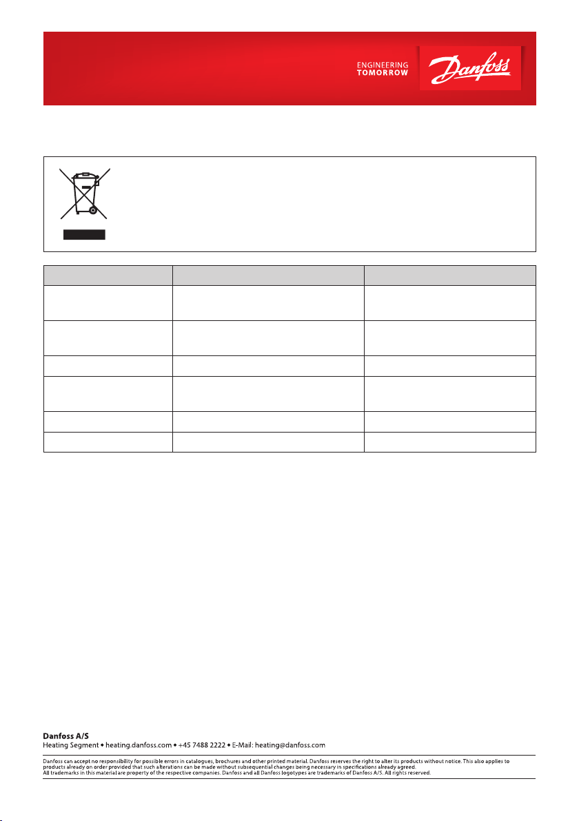
5. Disposal
This symbol on the product indicates that it will not be treated as household waste.
It must be handed over to the applicable take-back scheme for the recycling of electrical and electronic equipment. For more detailed information about the recycling
of this product, please contact your local municipal office.
Item Material Disposal
Battery
PCBA with display
D cell lithium/thionyl chloride
5,7 g lithium
Coppered epoxy laminate components soldered on, PC, TPE
Cables Copper with PUR or PVC jackets Cable recovery
Flow sensor (incl.
transducer and liner)
Brass, stainless steel, PPS Metal recovery
Transducer PZT, stainless steel, PEI Approved deposit for PZT
Other plastic parts PC, PPS, PEI, TPE Plastic recovery
Approved deposit for lithium
batteries
Electronic waste
12 | © Danfoss | DHS-SRMT / PL | 2018.08 VI.SH.O2.02
 Loading...