

Page 1
Data sheet
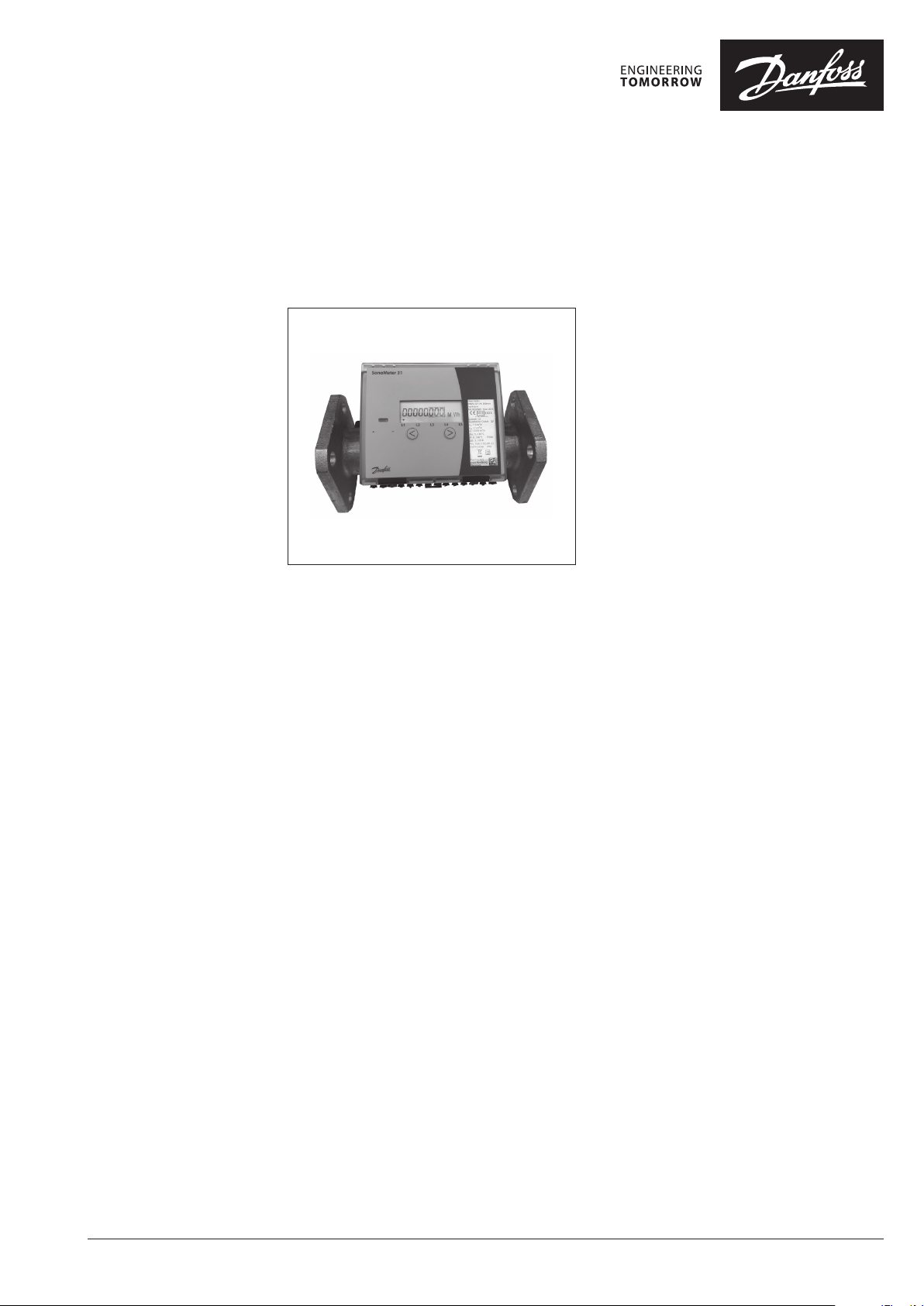
SonoMeter 31
Energy Meters
Description
MID examination cer tificate no.:
LT-1621- M I 00 4 - 0 23
The Danfoss SonoMeter 31 is a range of
ultrasonic, compact energy meters intended for
measuring energy consumption in heating and
cooling applications for billing purposes. The
meters are designed for remote meter read-out
(AMR).
SonoMeter 31 energy meters consist of
an ultrasonic flow sensor, a pair of Pt500
temperature sensors and a calculator
with integrated circuits for temperature
measurement, flow calculation and energy
calculation.
Features
• Available in nominal flow rates
qp 25, 40 and 60 m³/h
• DN 65, DN 80 and DN 100 housings with
flange connections
• MID approval for ultrasonic energy meter with
dynamic range of 1:100 (qi : qp) in class 2
• Optional MID approved dynamic range of
1:250 (qi : qp) in class 2
• Temperature range 5 –130 °C
• Short overload temperature up to 150 °C
• Operating pressure 25 bar as standard
• For 2 or 4 wire temperature sensors
• Glycol mixtures as option (not MID certified)
• Calculator with IP65 protection class as
standard
• Flow sensor with IP65 protection class as
standard (IP67 for combine heating and
cooling applications)
• Return or supply pipe installation, for vertical
or horizontal mounting
• Battery lifetime for at least 10 years
• Insensitive to dirt
• Remote reading via wired M-Bus, radio OMS
868 MHz, RS-485 Modbus RTU, pulse output,
analog output and optical interface
• Two pulse inputs as standard (passive or
active)
• Special option with 2 flow sensors, 2
pressure sensors and 3 temperature sensors
measurement
© Danfoss | 2019.04 VD.SH.V3.02 | 1
Page 2
Data sheet SonoMeter 31 - Energy Meters
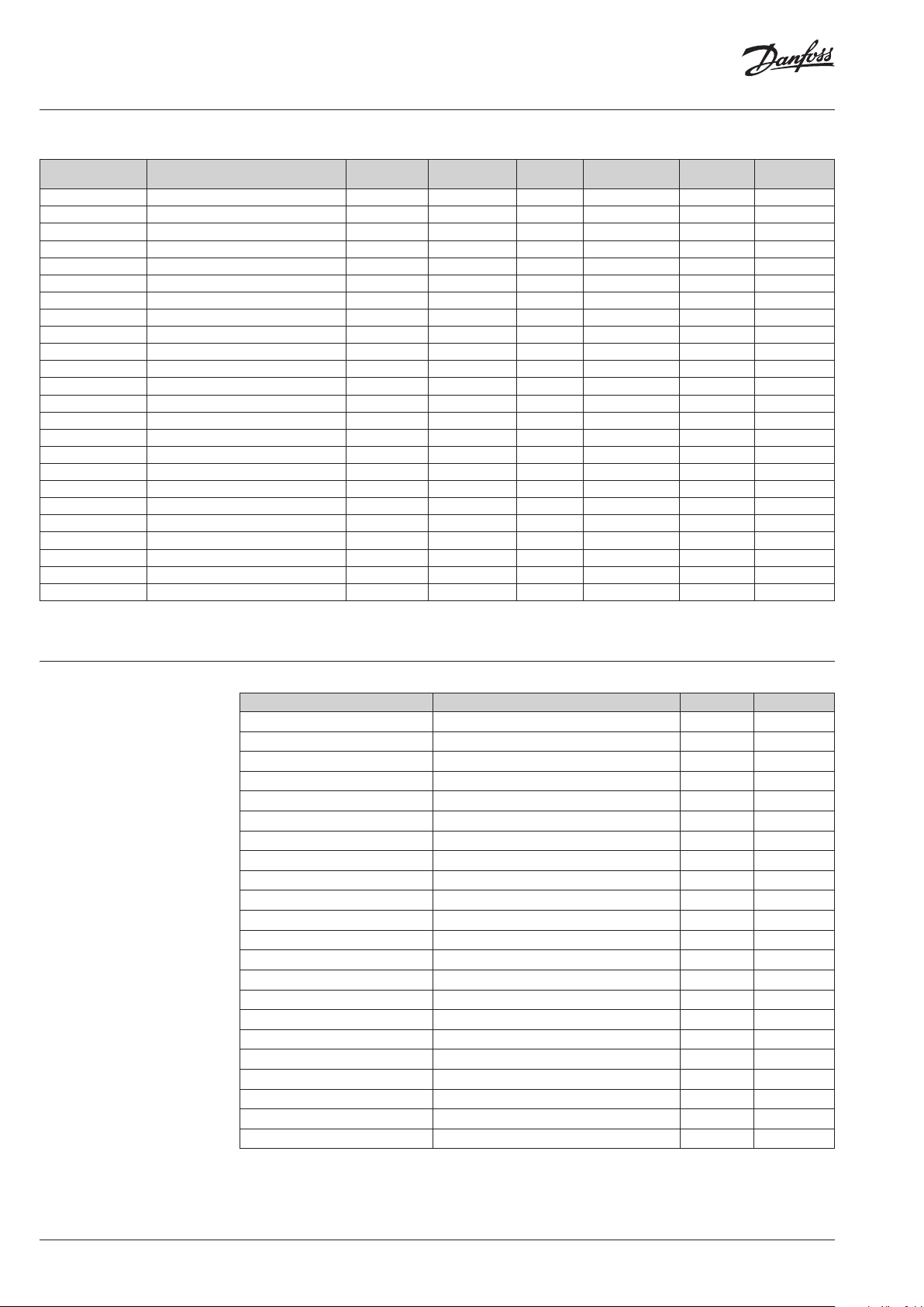
Ordering
Energy meter
application
Heating DN 65 / qp 25 m³/h / 300mm flange M-Bus MWh (2 dig.) Return batter y 3.6 V DC 25 bar 187F3300
Heating DN 65 / qp 25 m³/h / 300mm flange OMS 868.95 MWh (2 dig.) Return battery 3.6 V DC 25 bar 187F3301
Heating DN 65 / qp 25 m³/h / 300mm flange M-Bus MWh (2 dig.) Return mains 230 V AC 25 bar 187F3302
Heating DN 65 / qp 25 m³/h / 300mm flange OMS 868.95 MWh (2 dig.) Return mains 230 V AC 25 bar 187F3303
Heating / cooling DN 65 / qp 25 m³/h / 300mm flange M-Bus MWh (2 dig.) Return batter y 3.6 V DC 25 bar 187F3304
Heating / cooling DN 65 / qp 25 m³/h / 300mm flange OMS 868.95 MWh (2 dig.) Return battery 3.6 V DC 25 bar 187F3305
Heating / cooling DN 65 / qp 25 m³/h / 300mm flange M-Bus MWh (2 dig.) Return mains 230 V AC 25 bar 187F3306
Heating / cooling DN 65 / qp 25 m³/h / 300mm flange OMS 868.95 MWh (2 dig.) Return mains 230 V AC 25 bar 187F3307
Heating DN 80 / qp 40 m³/h / 350mm flange M-Bus MWh (2 dig.) Return battery 3.6 V DC 25 bar 187F3308
Heating DN 80 / qp 40 m³/h / 350mm flange OMS 868.95 MWh (2 dig.) Return battery 3.6 V DC 25 bar 187F3309
Heating DN 80 / qp 40 m³/h / 350mm flange M-Bus MWh (2 dig.) Return mains 230 V AC 25 bar 187F3310
Heating DN 80 / qp 40 m³/h / 350mm flange OMS 868.95 MWh (2 dig.) Return mains 230 V AC 25 bar 187F3311
Heating / cooling DN 80 / qp 40 m³/h / 350mm flange M-Bus MWh (2 dig.) Return battery 3.6 V DC 25 bar 187F3312
Heating / cooling DN 80 / qp 40 m³/h / 350mm flange OMS 868.95 MWh (2 dig.) Return battery 3.6 V DC 25 bar 187F3313
Heating / cooling DN 80 / qp 40 m³/h / 350mm flange M-Bus MWh (2 dig.) Return mains 230 V AC 25 bar 187F3314
Heating / cooling DN 80 / qp 40 m³/h / 350mm flange OMS 868.95 MWh (2 dig.) Return mains 230 V AC 25 bar 187F3315
Heating DN 100 / qp 60 m³/h / 350mm flange M-Bus MWh (2 dig.) Return batter y 3.6 V DC 25 bar 187F3316
Heating DN 100 / qp 60 m³/h / 350mm flange OMS 868.95 MWh (2 dig.) Return battery 3.6 V DC 25 bar 187F3317
Heating DN 100 / qp 60 m³/h / 350mm flange M-Bus MWh (2 dig.) Return mains 230 V AC 25 bar 187F3318
Heating DN 100 / qp 60 m³/h / 350mm flange OMS 868.95 MWh (2 dig.) Return mains 230 V AC 25 bar 187F3319
Heating / cooling DN 100 / qp 60 m³/h / 350mm flange M-Bus MWh (2 dig.) Return batter y 3.6 V DC 25 bar 187F3320
Heating / cooling DN 100 / qp 60 m³/h / 350mm flange OMS 868.95 MWh (2 dig.) Return battery 3.6 V DC 25 bar 187F3321
Heating / cooling DN 100 / qp 60 m³/h / 350mm flange M-Bus MWh (2 dig.) Return mains 230 V AC 25 bar 187F3322
Heating / cooling DN 100 / qp 60 m³/h / 350mm flange OMS 868.95 MWh (2 dig.) Return mains 230 V AC 25 bar 187F3323
Cable length of te mperature sensors is 3.0m .
Cable length b etween flow sensor an d energy calculator is 3.0m.
Nominal flow, size
and connection type
Comm.
module
Energy unit Installation
Power
supply
Operating
pressure
Code no.
Accessories
Product Designation Quantity Code no.
Power supply Battery 3.6 V DC (D cell) 1 pc. 187F3380
Power supply Mains unit 230 V AC 1 pc. 187F3381
Communication module M-Bus module 1 pc. 187F3382
Communication module Radio OMS 868.95 MHz 1 pc. 187F3383
Communication module RS-485 Modbus RTU 1 pc. 187F3384
Communication module RS-232 M-Bus 1 pc. 187F3385
Communication module RS-485 M-Bus
Communication module M-Bus, RS232 and two pulses outputs
Communication module M-Bus, RS232 and two 4-20mA outputs
1)
1)
1)
1 pc. 187F3386
1 pc. 187F3387
1 pc. 187F3388
Temperature sensor Pt 500 / f 5.2 mm / 1.5 m cable, MID 1 pair 187F312 5
Temperature sensor Pt 500 / f 5.2 mm / 2 m cable, MID 1 pair 187F312 6
Temperature sensor Pt 500 / f 5.2 mm / 3 m cable, MID 1 pair 187F3127
Temperature sensor Pt 500 / f 5.2 mm / 5 m cable, MID 1 pair 187F3390
Temperature sensor Pt 500 / f 5.2 mm / 10 m cable, MID 1 pair 187F3391
Sensor pockets Ø 5.2 mm, brass, 35 mm length 1 pair 087G6053
Sensor pockets Ø 5.2 mm, brass, 52 mm length 1 pair 087G6054
Sensor pockets Ø 5.2 mm, brass, 85 mm length 1 pair 087G6055
Sensor pockets Ø 5.2 mm, brass, 120 mm length 1 pair 087G6056
Sensor pockets Ø 5.2 mm, stainless steel, 85 mm length 1 pair 087G6057
Sensor pockets Ø 5.2 mm, stainless steel, 120 mm length 1 pair 087G6058
Sensor pockets Ø 5.2 mm, stainless steel, 155 mm length 1 pair 087G6059
Sensor pockets Ø 5.2 mm, stainless steel, 210 mm length 1 pair 087G6060
1) Only with mains suppl y 230 V AC
2 | VD.SH.V3.02 © Danfoss | 2019.04
Page 3
Data sheet SonoMeter 31 - Energy Meters
Technical specifications
Diameter D N 65 DN 80 DN 10 0
Connection type EN1092 flange
Overall length (mm) 300 350 350
Flow rate:
Nominal (m3/h) 25 40 60
Maximum (m3/h) 50 80 120
Standard min. (m3/h) 0.25 0.4 0.6
Star ting (m3/h) 0.10 0.16 0.24
Max. operating pressure 25 bar
Flow sensor temp. range 5 to 130 °C (short overload up to 150 °C)
Flow sensor cable length 3.0 m
Medium Water quality with pH 7 to 9.5
Pressure loss at qp, mbar 200 18 0 180
Measuring cycles Volume every 1 sec., energy, temperature sensors and display update every 10 sec.
Temperature sensors Pt 500 ø 5.2 mm with 2-wire leads
Temp. sensor cable length 3.0 m
Max. temp. diff. (∆θma x) 150 K
Min. temp. diff. (∆θmin) 3.0 K
Starting temp. diff. (∆θ) 0.15 K
Temp. measuring range 0 to 180 °C
Supply voltage 3.6 V DC Lithium-battery (D-cell) or Mains supply 230 V AC
Battery life time min. 10 years (including AMR communication)
Approval EN1434 class 2
Environmental class EN1434 class C
Ambient class class E2 + M1
Protection class Calculator: IP 65; Flow sensor: IP 65 (IP67 for heat and cooling meter)
Ambient operating temp. Calculator: 5 to 55 °C; Flow sensor: -30 to 55 °C
Ambient storage and
transportation temp.
Max. ambient humidity 93% rel. humidity
Display LCD, 8-digit
Display units MWh - kWh - GJ - Gcal - °C - m3 - m3/h
Display values Energy - volume - flow rate - power - temperatures
5 to 55 °C
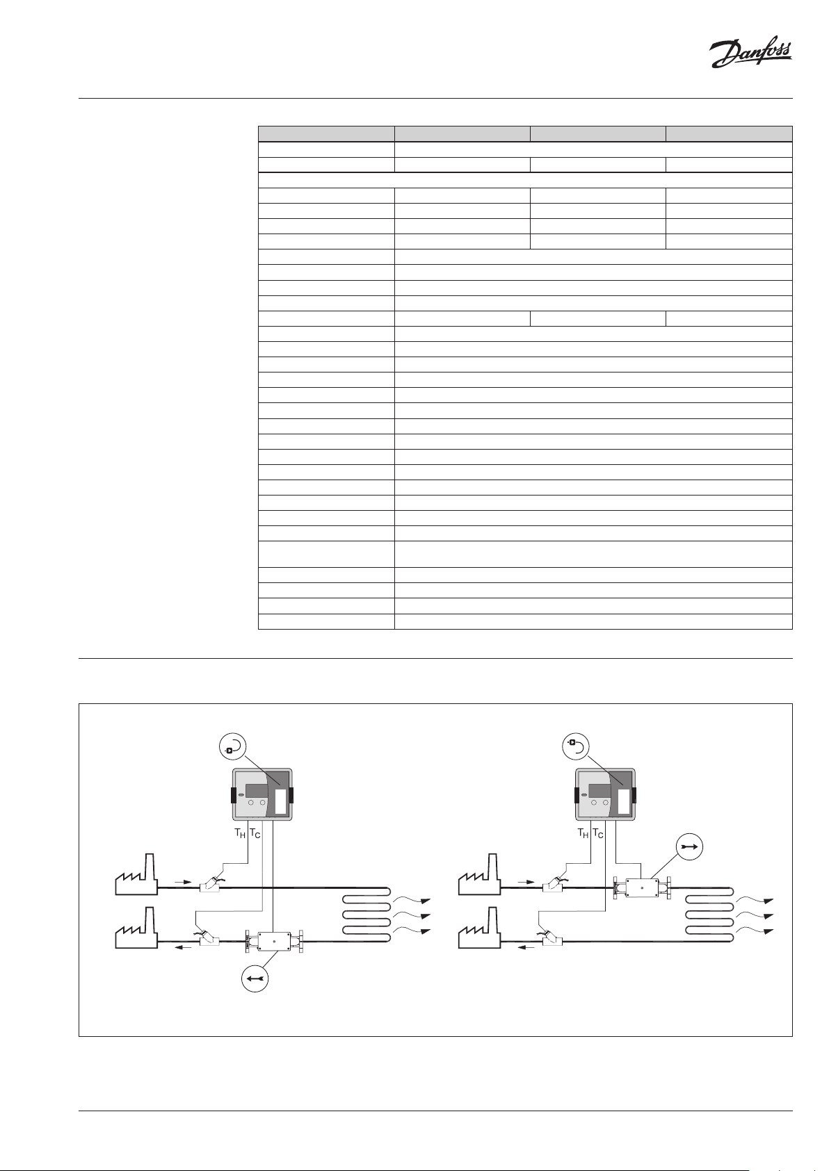
Application drawings
Return pipe installation Supply pipe installation
Flow direction
Flow direction
VD.SH.V3.02 | 3© Danfoss | 2019.04
Page 4

Data sheet SonoMeter 31 - Energy Meters
5
-1
-2
-3
-4
-5
Accuracy
4
3
2
1
0
Error [%]
Pressure loss
q
i
Measuring accuracy class 2
qpq
s
4 | VD.SH.V3.02 © Danfoss | 2019.04
Page 5

Data sheet SonoMeter 31 - Energy Meters
Design and function
Optical interface
Optical interface is integrated into the front panel of the calculator. It is designed for data reading via
M-bus protocol.
The optical interface is activated by pressing the control button and shuts automatically off 5 minutes
after the last pressing button or after completing data transmission via interface.
Wired M-Bus interface
The energy meter has 1 slot for an additional communication module. The internal M-Bus module
provides data reading possibility via M-Bus protocol:
• M-Bus protocol according to EN13757-3 standard
• 2-wire with polarity reversal protection
• Electrical isolation
• Maximum voltage 50 V DC
• Current drawn: one M-Bus load (1.5 mA)
• Primary or secondary addressing
• Baud rate 300/1200/2400/4800/9600 bps (default: 2400 baud rate)
• Battery lifetime min. 10 years (1 D cell)
• Fastest reading interval at battery supply: every 90 seconds (at 9600 b/s, internally protected)
• Fastest reading interval at mains supply: no limits (auto at order or manual if added later)
Radio OMS 868.95 MHz interface
The module can provide data reading via radio module:
• Wireless M-Bus protocol according to EN13757-4
• OMS (open metering system) compatible
• T1 mode (unidirectional)
• Sending interval every 90 seconds (suitable for ‘walk by’ readings)
Modbus RS-485 module
RS-485 module is Modbus RTU protocol and a serial interface for communication with external
devices.
Baud rate 1200, 2400, 4800, 9600 (default), 38400, 56000, 57600, 115200 bps
Polarity independent connection for power supply – connectors 60 and 61.
Power supply
Voltage 12-24 V AC/DC.
Maximum power consumption 2 W max.
Typical supply current 50 mA .
Pulse inputs
Data logger
Number of pulse inputs 2
Measurement units m
Pulse value configurable by control buttons
Min. pulse time 100 m s
Pulse type IB by LST EN1434-2
Max. frequency of input pulses 5 Hz
Max. voltage of input pulses 3.6 V
Data logger
3
Daily, weekly and monthly parameter values and
errors are recorded in heat meter memory:
Data logger capacity
up to 110 days (3,5 months) – for hourly records.
up to 1461 days (36 last months) - for daily and
monthly records.
Power supply Power supply (one of following depending on
meter configuration):
• 1 D-cell battery 3.6 V DC, 19 Ah (ER 34615)
lithium battery, life time at least 10 years.
• Mains power supply 230 V AC 50 (+/− 2) Hz .
Retention time of measured integrated
parameters even if device is disconnected from
power supply not more than 12 years.
VD.SH.V3.02 | 5© Danfoss | 2019.04
Page 6

Data sheet SonoMeter 31 - Energy Meters
Display symbols
description
Parameter and group numbers
Operation mode
Display menu structure
∑
1-2 3-4 5
Values
8:8:8.8.8.8.8.8
MAX
Group of parameters
Parameters shown Identification symbols
Integral values (L1)
Instantaneous parameters values (L2)
Set day parameters and archive data values (L3)
Printing reports by standard printer (L4)
Configuration settings parameters (L5)
Parametrization (configuration) mode (SET)
Test mode (TEST)
L1 L2 L3 L4 L5
HDM TEST SET
tm°/hkPa
°GJcal
MkWh
<R<MIN
L1 L2 L3 L4 L5
L1 L2 L3 L4 L5
L1 L2 L3 L4 L5
L1 L2 L3 L4 L5
L1 L2 L3 L4 L5
L1 L2 L3 L4 L5
L1 L2 L3 L4 L5
Measurement units
SET
TEST
Mounting
Pipe position: avoid position where air can
be collected.
Rotation in pipe axis
Inlet/outlet conditions In order to maximize performance it is necessary to have straight inlet and outlet flow conditions
before and after the flow sensor: 5 × DN on inlet and 3 × DN on outlet of flow sensor.
5 × DN 3 × DN
flow
6 | VD.SH.V3.02 © Danfoss | 2019.04
Page 7

Data sheet SonoMeter 31 - Energy Meters
Dimensions
Calculator
140
Flow sensor
sealing
159
142
80
119
~52
sealing
DN
65 / PN 16 300 185 185 145 200 4
65 / PN 25 300 185 185 145 200 8
80 350 200 200 160 215 8
100 350 220 220 180 235 8
L D H D1 B holes
mm
VD.SH.V3.02 | 7© Danfoss | 2019.04
Page 8

Danfos
produc
Al
Danfoss A/S
Heating Segment • heating
Data sheet SonoMeter 31 - Energy Meters
Dimensions (continuous)
Temperature sensors
Sensor pockets
Installation Typ e
Immersed (direct) or
in pocket (indirect)
Typ e Brass Stainless steel
Sensor
diameter
Length
(mm) ø 5.2 ø 5.2
L1
47 6 93 128 98 133 168 223
(mm)
L (mm) 35 52 85 12 85 12 155 21
Pt 5 ø 5.2 45
Diameter
D (mm)
Length
L (mm)
s can accept no responsibility for possible errors in catalogues, brochures and o ther printed material. Danfoss reserves the right to alter its products w ithout notice. This also applies to
ts already on order provided that such alterations can be m ade without subsequential changes being necessary in specications already agreed.
l trademarks in this material are p roperty of the respective companies. Danfoss and all Danfoss l ogotypes are trademarks of Danfoss A/S. All rights reserve d.
.danfoss.com • +45 7488 2222 • E-Mail: heating@danfoss.com
© Danfoss | DHS-SRMT/SI | 2019.048 | VD.SH.V3.02
 Loading...