

Installation guide
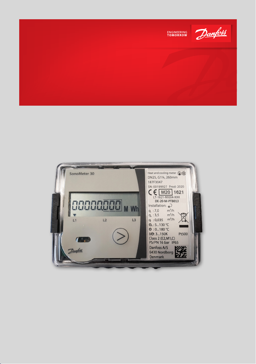
SonoMeter 30
Ultrasonic energy meter
for heating and cooling applications
www.danfoss.com
Date
Issued by
Place of issue
Date
Approved by
2018.04.26
Nordborg, DK
2018.04.26
Page 1 of 1
Danfoss A/S
DK
De
CVR nr.: 20 16 57 15
Teleph
Fax:
Installation guide SonoMeter 30
-6430 Nordborg
nmark
one: +45 7488 2222
+45 7449 0949
EU DECLARATION OF CONFORMITY
Danfoss A/S
declares under our sole responsibility that the
Product(s):
Energy Meters
Type(s):
SonoMeter 30
covered by this declaration is in conformity with the following directive(s), standard(s) or other normative
document(s), provided that the product is used in accordance with our instructions.
• MID Directive 2014/32/EU Measuring Instrument Dir ective
Module B +D
o EN1434-4:2015
Notified Body: Lithuanian Energy Institute , 1621, performed type approval and issued certificate
• EMC D irective 2014/30/EU Electromagnetic Compatibilit y
• RoHS Directive 2011/65/EU Restriction of Hazardous substances
• RED D irective 2014/53/EU Radio Equipment Directive
• LVD Directive 2014/35/EU L ow Voltage Directive
LT-1621-MI004-022
o EN 61000-6-1:2007
o EN 61000-6-3:2007/A1:2011
o EN 55022:2010
o EN 50581:2012
o EN 300 220-2 V3.1.1
o EN 301 489-1 V1.9.2:2011-09
o EN 301 489-3 V1.6.1:2013-06
o EN 62311:2008
o EN 61010-1:2010
o EN 60950-1:2006/A11:2009/A1:2010/A12:2011/AC:2011/A2:2013
o EN 62311:2008
o EN 61010-1:2010
o EN 60950-1:2006/A11:2009/A1:2010/A12:2011/AC:2011/A2:2013
• PED Directive 2017/68/EU
1
For variants with Radio Module the declaration for EMC & LVD shall be ignored
2
For variants without Radio Module the declaration for RED shall be ignored
Kim Jessen
Approval Engineer, Danfoss Ener gy Metering
Danfoss only vouches for the correctness of th e English version of this declaration. In the event of the declaration being t ranslated into any other
language, the translator concerned shall be li able for the correctness of the translation
ID No: VJSHO202 Revision No: 1
Danfoss Energy Metering
1
2
1
Jeppe Molleskov Blasbjerg
Energy Metering Category Manager
2 | © Danfoss | Energy Meters | 2020.11 BC200586470576en-020601
Installation guide SonoMeter 30
1. Installation
1.1. Preparation
Only qualified personnel may install the equipment, following the requirements listed in this document.
More detailed instruction can be found on www.heating.danfoss.com.
Note! This product is approved for ambient temperature between 5-55° C, but to ensure optimal conditions for
battery it is recommended to install Calculator at max. 45° C. Avoid installation stress from pipes and fittings.
Flush the system.
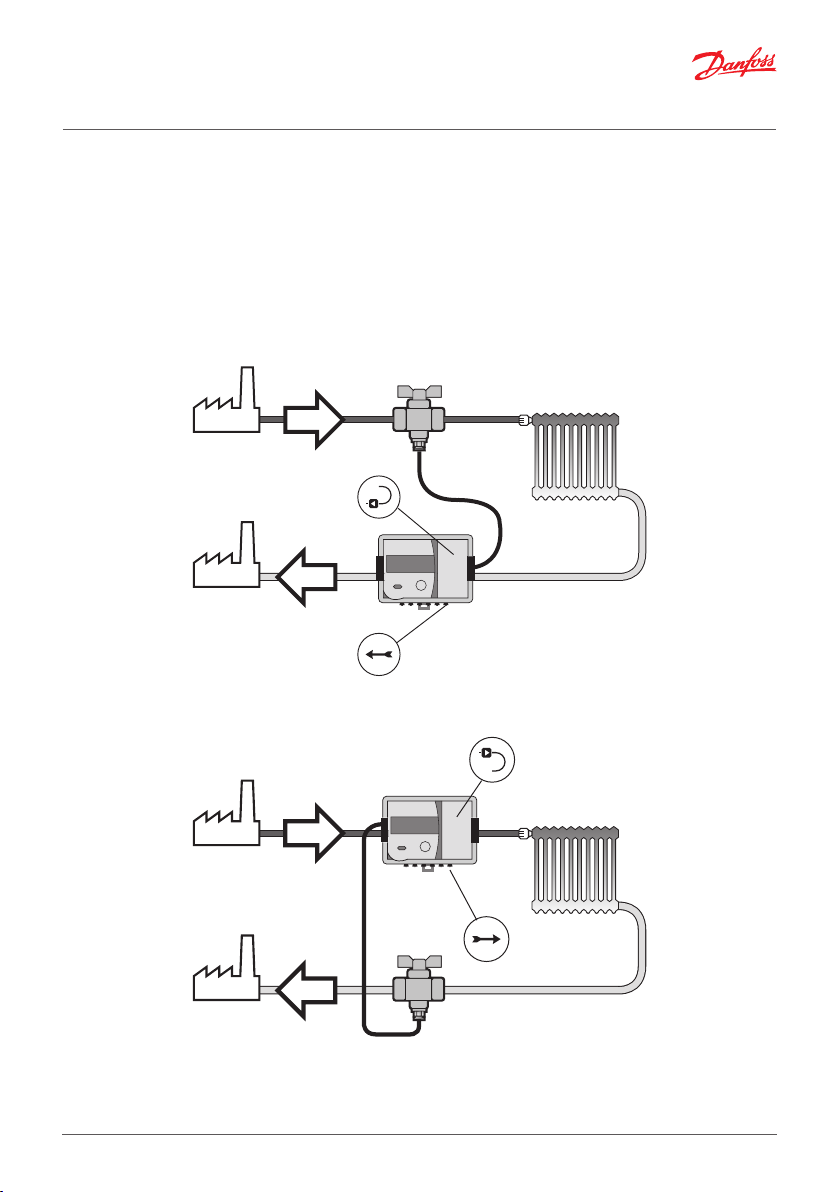
1.2. Identification of installation: Return/Supply pipe installation and flow direction
Flow direction
Return pipe installation
Flow direction
Supply pipe installation
BC200586470576en-020601 © Danfoss | Energy Meters | 2020.11 | 3
Installation guide SonoMeter 30
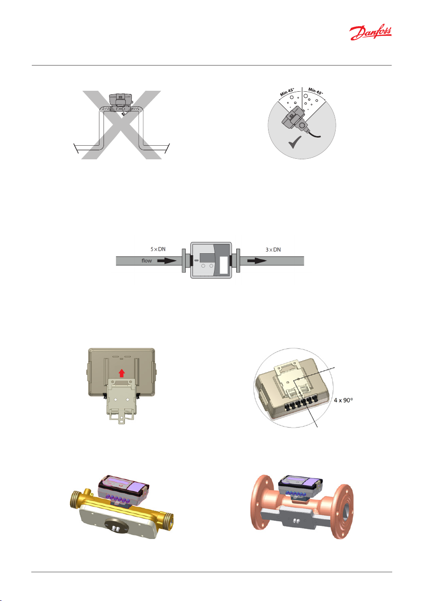
1.3. Mounting of flow sensor
Pipe position: No limitations but avoid positions
where air can be collected.
Inlet/outlet conditions (only for DN 65-DN 100)
In order to maximize performance it is necessary to have straight inlet and outlet flow conditions before
and after the flow sensor: 5 × DN on inlet and 3 × DN on outlet of flow sensor.
1.4. Mounting and sealing of calculator
Heat meter calculator may be installed in heated premises, working ambient temperature shall
be not more than 55 °C. It may not be exposed to direct sunlight.
The calculator is mounted on an auxiliary holder (it can be oriented in the required direction at an angle of
each 90 °:
The possible ways of the mounting of the calculator (auxiliary holder):
- Direct mounting on the housing of the flow sensor, by turning each 90o (only when the flow temperature
does not exceed 90oC):
Rotation in pipe axis: Flow sensor should be angled
in 45 to 315° to avoid air collection in flow sensor.
4 | © Danfoss | Energy Meters | 2020.11 BC200586470576en-020601

Installation guide SonoMeter 30
- On the wall:
- Panel mounting on standard DIN-rail.
- Adapter plate according to figure 8 of EN1434-2:2007 for wall mounting of calculator can be used (if the
aperture in the wall is too large for the calculator):
Important: It is forbidden to attach the calculator directly to a wall if there is a risk that on walls can
be condensed humidity or temperature of a surface of a wall can fall lower than 5°C. In this case, it is
recommended to attach the calculator so that between it and wall surfaces there was an air gap not
less than 5 cm.
BC200586470576en-020601 © Danfoss | Energy Meters | 2020.11 | 5

Installation guide SonoMeter 30
Seal
Seal
Seal
ocket
Calculator seals
1: Manufacturer adhesive seal-sticker on the access to the adjustment activation jumper -verification seal.
2: Manufacturer adhesive seal-sticker on the fixer of the cover protecting electronic module -manufacturer
security seal.
3: Mounting seal after installation.
1.5. Mounting and sealing of temperature sensors
Installation recommendations for
ball valve mounting and sealing
Seal
Pocket
a) angled 45°
Installation recommendations for pocket temperature sensors with permanently connected signal leads.
6 | © Danfoss | Energy Meters | 2020.11 BC200586470576en-020601
Installation recommendations for
direct short temperature sensors
P
b) perpendicular

Installation guide SonoMeter 30
1.6. Setting up the jumpers (J)
The connector J is on the calculator plate between the temperature sensors and pulse input / output connection terminals (see 6.3). Joining or leaving open the connector contacts, you can choose the normal or
verification (test) mode, activate the pulse inputs or outputs:
Jumper is not set
(contacts are opened)
NORMAL MODE VERIFICATION (TEST) MODE
The first pulse output V1 is active
(terminals 52,53).
Energy as default.
The second pulse output V2 is active
(terminals 50,51).
Volume as default.
Note: On delivery the heat meter is configured with two outputs.
2. Electrical wiring
Wiring diagram 1
Jumper settings:
1: Additional pulse input V2 is on.
2: Additional pulse input V1 is on.
Jumper is set
(contacts are connected)
The first pulse intput V1 is active
(terminals 52,53)
(Jumper must be removed when
operating in TEST mode)
The second pulse intput V2 is active
(terminals 50,51)
(Jumper must be removed when
operating in TEST mode)
T1: flow temperature sensor.
T2: return temperature sensor.
V1: additional pulse input/output 1.
V2: additional pulse input/output 2.
7 | © Danfoss | Energy Meters | 2020.11 BC200586470576en-020601

Installation guide SonoMeter 30
Wiring diagram 2
Connecting the meter to the mains
power supply, 24 V AC/DC.
230 V AC to 24 V AC transformer
must be used for connection to
230 V AC!
Calculator
Terminals Description
5 T1 supply temperature sensor
6 T1 supply temperature sensor
7 T2 return temperature sensor
8 T2 return temperature sensor
50 V2 additional pulse input/output GND
51 V2 additional pulse input/output (Volume output in TEST mode)
52 V1 additional pulse input/output GND
53 V1 additional pulse input/output (Energy output in TEST mode)
Communication modules
Terminals Description
24, 25 M-bus module (bipolar)
60, 61 12-24 V DC power supply voltage for Modbus and LON (bipolar)
90 RS-485 Modbus RTU module (+) or BACnet (+)
91 RS-485 Modbus RTU module (+) or BACnet (+)
96 LON module (line A)
97 LON module (line B)
8 | © Danfoss | Energy Meters | 2020.11 BC200586470576en-020601

Installation guide SonoMeter 30
External power supply module
Terminals Description
54 Mains supply 24 V AC/DC (bipolar)
55 Mains supply 24 V AC/DC (bipolar)
3. Commissioning
3.1. Bleeding
1. Bleed the system until the flow rate display is steady.
2. Make sure no error codes are displayed.
3. Check the display for a plausible indication of flow rate and temperatures.
3.2. IP class
Calculator IP65
Flow sensor IP65 for heat meter
IP67 for heat and cooling meter
4. Display function overview
4.1. Menu structure
L1
Integral parameters
L2
Statistical data
L3
Informative parameters
9 | © Danfoss | Energy Meters | 2020.11 BC200586470576en-020601
1.1 1.2 1.3 1.4 1.51.6 1.7
2.1 2.2 2.3 2.4 2.52.6.1 2.7.12xx 2.15.1
3.1 3.2 3.3 3.4 3.5
3.6.13.7 3x 3.15
1.8
1.9
Long press
Short press

Installation guide SonoMeter 30
4.2. Display symbols
Explanation of special symbols:
flow is flowing forward (right direction)
flow is flowing backwards (wrong direction)
no arrow
Explanation of other symbols are described in detailed instruction on www.heating.danfoss.com.
no flow
4.3. Error codes
Error codes may consist of up to 4 symbols.
Each symbol may have values 0…8
L1 L2 L3
Calculate errors
Temperature 2 errors
Temperature 1 errors
Flow errors
Code Description
Status of calculator 0 - no error, normal operation
1 - warning – ending battery life
2 - temperature difference is greater than the permitted limits
4 - temperature difference is less than the permitted limits
8 - electronics failure
Status of temperature
sensor 2 (return pipe)
0 - no error, normal operation
4 - short circuit
8 - sensor failure (open circuit or short circuit)
Status of temperature
sensor 1 (flow pipe)
0 - no error, normal operation
4 - short circuit
8 - sensor failure (open circuit or short circuit)
Status of flow sensor 0 - no error, normal operation
1 - no signal, flow sensor is empty
2 - flow flows in an reverse direction
4 - flow rate greater than 1.2∙qs (are displayed q = 1,2qs)
8 - electronics failure
Active error codes are added and simultaneously displayed, if more than one error is detected:
• 3 - corresponds errors 2 + 1
• 5 - corresponds errors 4 + 1
• 7 - corresponds errors 4 + 2 + 1
• 9 - corresponds errors 8 + 1
• A - corresponds errors 8 + 2
• B - corresponds errors 8 + 2 + 1
• C - corresponds errors 8+4
• D - corresponds errors 8 + 4 + 1
• E - corresponds errors 8 + 4 + 2
• F - corresponds errors 8 + 4 + 2 +1
10 | © Danfoss | Energy Meters | 2020.11 BC200586470576en-020601

Installation guide SonoMeter 30
5. Disposal
This symbol on the product indicates that it will not be treated as household waste.
It must be handed over to the applicable take-back scheme for the recycling of electrical and electronic equipment. For more detailed information about the recycling
of this product, please contact your local municipal office.
Item Material Disposal
Battery
PCBA with display
Cables Copper with PUR or PVC jackets Cable recovery
Flow sensor (incl. trans-
ducer and liner)
Transducer PZT, stainless steel, PEI Approved deposit for PZT
Other plastic parts PC, PPS, PEI, TPE Plastic recovery
AA-cell lithium/thionyl chloride 700 mg
lithium
Coppered epoxy laminate components
soldered on, PC, TPE
Brass, stainless steel, PPS Metal recovery
Approved deposit for lithium
batteries
Electronic waste
6. Local Importer name and address
For goods delivered to UK, importer name and address is:
Danfoss Ltd.
Oxford Road
UB9 4LH Denham
UK
11 | © Danfoss | Energy Meters | 2020.11 BC200586470576en-020601

12 | © Danfoss | Energy Meters | 2020.11 BC200586470576en-020601
 Loading...