

Page 1
Data sheet
SonoMeter 30
Energy Meters
Description
The Danfoss SonoMeter 30 is a range of
ultrasonic, compact energy meters intended for
measuring energy consumption in heating and
cooling applications for billing purposes. The
meters are designed for remote meter read-out
(AMR).
SonoMeter 30 energy meters consist of
an ultrasonic flow sensor, a pair of Pt500
temperature sensors and a calculator
with integrated circuits for temperature
measurement, flow calculation and energy
calculation.
Features
• Available in nominal flow rates qp 0.6, 1.5, 2.5,
3.5, 6.0, 10.0, 15.0, 25.0, 40.0 and 60 m3/h
• Housings with thread (G3/4 to G2) or flange (DN
20 to DN 100) connections
• MID approval for ultrasonic energy meter with
dynamic range of 1:100 (qi:qp) in class 2
• Optional MID approved dynamic range of 1:250
in class 2 for qp 1.5, 2.5, 6.0, 10 and 15 m3/h
• Temperature range 5 - 130 °C, PN 16 or 25 bar
• Short overload temperature up to 150 °C
• Glycol mixtures as option up to incl. DN 50 (not
MID certified)
• Calculator with IP 65 protection class as standard
• Flow sensor with IP 65 protection class as
standard (IP67 for combine heating and cooling
applications)
• Return or supply pipe installation, for vertical or
horizontal mounting
• Battery lifetime for at least 11 years
• Low pressure loss, insensitive to dirt
• No calming sections needed before or after the
flow sensor (DN 15-DN 50)
• For DN 65 to DN 100 calming sections are
needed (5 x DN on inlet and 3 × DN on outlet of
flow sensor)
• Remote reading via M-Bus, radio OMS 868 Mhz,
RS 485 Modbus, BACnet, pulse output or optial
interface
• Two pulse inputs or outputs as standard
(default delivered as pulse output - can be
changed)
© Danfoss | Energy Meters | 2020.08 AI206286471334en-010701 | 1
Page 2
Data sheet SonoMeter 30
Technical specifications
Diameter DN 15 DN 20 DN 15 DN 20 DN 20 DN 25 D N 25 DN 40 DN 50 DN 65 DN 80 DN 100
Connection type G¾B G1B FL G¾B G1B FL G1B G1B G1B FL G1¼ B FL G1¼ B FL G2B FL FL FL FL FL
Overall length, mm 110 190 110 190 130 130 19 0 260 26 0 300 270 30 0 300 360
Flow rate:
Nominal (m3/h) 0.6 1.5 2.5 3.5 6 10 15 25 40 60
Maximum (m3/h) 1.2 3 5 7 12 20 30 50 80 120
Standard min. (l/h) 6 15 25 35 60 100 150 350 400 600
Pressure l oss at qp (mbar)
Kvs values (for nominal flow)
Max. operating pressure 16 bar / 25 bar
Flow sensor temp. range 5 to 130 °C (short ove rload to 150 °C)
Flow sensor cable length 1.2m, 2.5m a nd 5m (optional)
Medium Water quali ty with pH 7 to 9.5
Measuring cycles Volume ever y 1 sec., energ y, temper ature sensors and d isplay update ever y 16 sec.
Temperature sensors Pt 500 ø 5. 2 mm with 2-wire lead s
Temp. sensor cable length 1.5 m option al 3 m, 5 m and 10 m cable
Max. tem p. diff. (∆θmax) 150 K
Min. temp. d iff. (∆θmin) 3.0 K
Starti ng temp. diff. (∆θ) 0.15 K
Temp. measuring range 0 to 180 °C
Supply voltage
Batter y life time min. 11 years (including AMR communication)
Approval EN1434 class 2
Environmental class EN1434 class C
Ambient class class E2 + M1
Protection class Calculat or: IP 65; Flow sensor : IP 65 (IP67 for heat and coo ling meter)
Ambient operating temp. Calculat or: 5 to 55 °C; Flow senso r: -30 to 55 °C
Ambient storage and
transporta tion temp.
Max. amb ient humidity 93% rel. humi dity
Display LCD, 8- digit
Display units MWh - k Wh - GJ - Gcal - °C - m3 - m3/h
Display values Ener gy - volume - flow r ate - power - tempera tures
70 9 171 58 72 198 94 40 100 180 120 200 18 0 180
2.27 6.32 3.63 6.23 5.59 5.62 8 .15 17. 50 18.97 23.57 43.50 55.9 94.3 141 .4
3.6 V DC Lith ium-batter y (AA cell) / Mains su pply 24 V AC/DC.
Mains supp ly 230 V AC (with exter nal 230 V AC to 24 V AC transform er).
5 to 55 °C
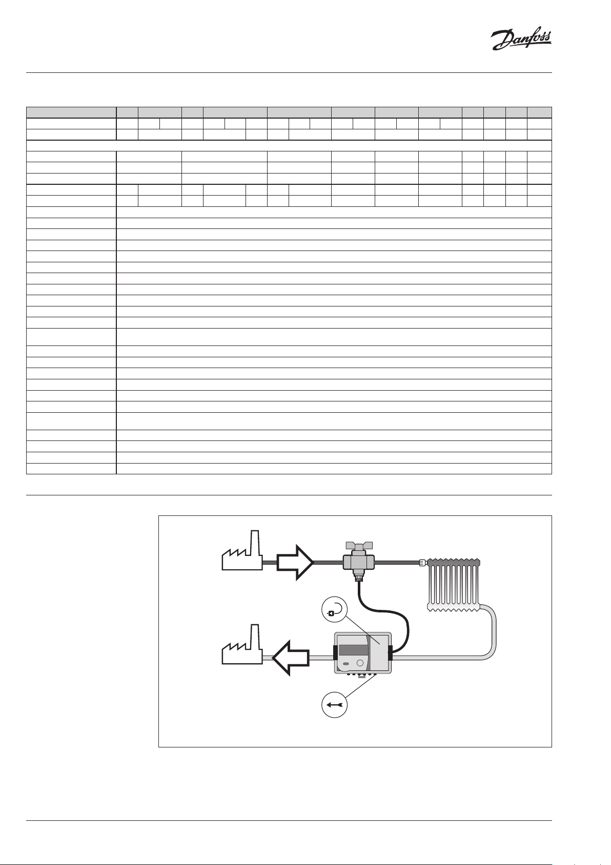
Application drawings
Flow direction
Return pipe installation
2 | AI206286471334en-010701 © Danfoss | Energy Meters | 2020.08
Page 3
Data sheet SonoMeter 30
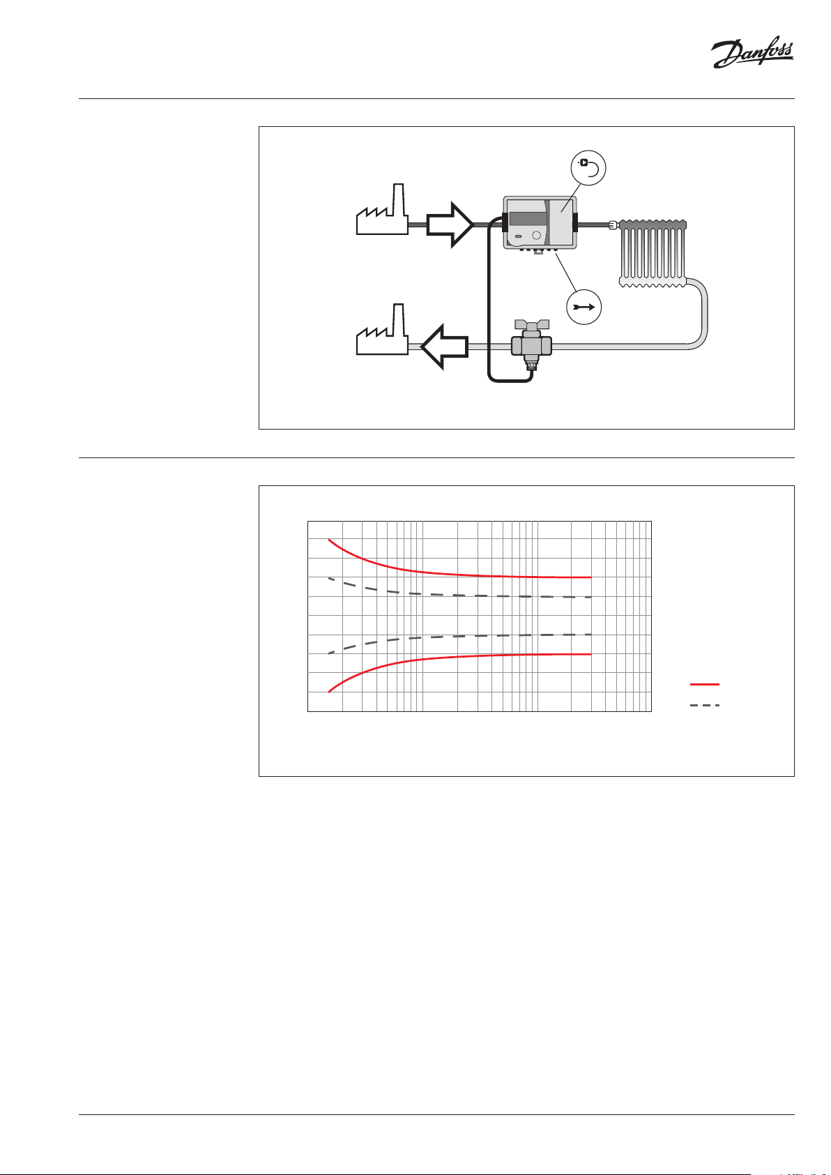
5
4
3
2
1
0
-1
-2
-3
-4
-5
q
i
qpq
s
EN1434 class 2
Key
typical accuracy
Application drawings
(continuous)
Supply pipe installation
Accuracy
Flow direction
Error [%]
Flow measurment accuracy
AI206286471334en-010701 | 3© Danfoss | Energy Meters | 2020.08
Page 4

Data sheet SonoMeter 30
Design and function
Optical interface
Optical interface is integrated into the front panel of the calculator. It is designed for data reading
via M-bus protocol and parameterization of the meter using SonoMeter 30 UserConfig software and
optical head OG-1-USB.
The optical interface is activated by pressing the control button and shuts automatically off 5 minutes
after the last pressing button or after completing data transmission via interface.
Wired M-Bus interface
The energy meter has 1 slot for an additional communication module. The internal M-Bus module
provides data reading possibility via M-Bus protocol:
• M-Bus protocol according to EN13757-3 standard
• 2-wire with polarity reversal protection
• Electrical isolation
• •Maximum voltage 50 V DC
• Current drawn: one M-Bus load (1.5 mA)
• Primary or secondary addressing
• Baud rate 2400 bps
• Battery lifetime min. 11 years (2 AA cell)
• Battery supply communication is limited on every 15 min at 2400 baud rate or faster, 70 meters
on bus
• Fastest reading interval at mains supply: no limits
Radio OMS 868.95 MHz interface
• The module can provide data reading via radio module:
• Wireless M-Bus protocol according to EN13757-4
• OMS (open metering system) compatible, compliant to OMS 4.0.2
• T1 mode (unidirectional)
• Sending interval every 90 seconds (suitable for ‘walk by’ readings)
Modbus RS-485 module
RS-485 module is Modbus RTU protocol and a serial interface for communication with external
devices.
Baud rate 1200, 2400, 4800, 9600(default), 38400, 56000, 57600, 115200 bps
Polarity independent connection for power supply – connectors 60
and 61.
Power supply
BACnet
Baud rate 9600, 19200, 38400 –default, 57600, 76800, 115200 bps
Power supply
2 pulse inputs or 2 pulse outputs (set up by jumpers)
There is a connector J on the calculator plate between the temperature sensors and pulse input /
output connection terminals. By means of connecting or opening the connector contacts, the pulse
inputs or outputs are activated.
Note: On delivery the heat meter is configured with two outputs.
Pulse inputs (not default, jumper set needed)
Number of pulse inputs 2
Measurement units m3 (51, 52), kWh (52, 53) or MWh, GJ, GCal
Pulse value programmable by SonoMeter 30 UserConfig Software
Min. pulse time 100 ms
Pulse type IB by class IB according to EN1434-2
Max. frequency of input
pulses
Max. voltage of input pulses 3.6 V
Voltage 12-24 V AC/DC.
Maximum power consumption 2 W max.
Typical supply current 50 mA.
Polarity independent connection for power supply – connectors 60
and 61.
Voltage 12-24 V AC/DC.
Maximum power consumption 2 W max.
Typical supply current 50 mA.
3 Hz
4 | AI206286471334en-010701 © Danfoss | Energy Meters | 2020.08
Page 5

Data sheet SonoMeter 30
Design and function
(continuous)
Data logger
Pulse outputs (default, no jumper set)
Number of pulse outputs 2
Measurement units m3 (51, 52), kWh (52, 53) or MWh, GJ, GCal,
Pulse value according to the table below
Pulse type
open collector, permissible current up to 20 mA, voltage up to
50 V, class OB according to EN1434-2
Max. frequency of output pulses 3 Hz
Pulse duration 100 ms in normal mode, 1.6 ms in the test mode
Energy pulse output values (V1)
Energy units kWh or MWh GJ Gcal
Pulse value of thermal energy 1 kWh/pulse 0.005 GJ/pulse 0.001 Gcal/pulse
Volume pulse output values (V2)
Nominal flow rate (qp), m3/h 0.6 - 6 10; 15
Pulse value, l/pulse 1 10
Data logger
Following hourly, daily and monthly parameter values are recorded in energy meter memory (can be
configured by SonoMeter 30 UserConfig software):
1 ............Integrated heating energy
2 ............Integrated cooling energy
3 ............Integrated energy of tariff 1
4 ............Integrated energy of tariff 2
5 ............Integrated volume of liquid
6 ............Integrated pulse value in pulse input 1
7 ............Integrated pulse value in pulse input 2
8 ............Maximum thermal power value for heating and date
9 ............Maximum thermal power value for cooling and date
10 .......... Maximum flow rate value and date
11 ..........Maximum value of flow temperature of heat conveying liquid and date
12 .......... Maximum value of return temperature of heat conveying liquid and date
13 .......... Minimum value of flow temperature of heat conveying liquid and date
14 .......... Minimum value of return temperature of heat conveying liquid and date
15 .......... Minimum value of temperature difference and date
16 .......... Average value of flow temperature of heat conveying liquid
17 .......... Average value of return temperature of heat conveying liquid
18 .......... Operating time without an error of thermal energy calculation
19 .......... Total error code
20 ..........Time when the flow rate exceeded 1.2 q
21 .......... Time when the flow rate was less than q
s
i
Power supply
Data logger capacity
• up to 1480 h - for hourly records
• up to 1130 days - for daily records
• up to 36 last months - for monthly records
• Storage time of measured integrated parameters even if device is disconnected from power supply:
not less than 15 years
All data from archive can be read by means of the remote reading. In addition data logger records of
monthly parameters can be seen on the display.
Power supply (one of following depending on meter configuration):
• 2 AA cell battery 3.6 V DC, 2.4 Ah (Li-SOCl2) lithium battery, life time at least 11 years
• Mains power supply 12 V AC to 36 V AC (50/60 Hz) or 12 V DC to 42 V DC:
- The mains power supply 24V AC/DC module is mounted inside in the meter
- Consumption is max 20 mA
- Galvanically isolated + internal backup battery size AA cell, 3.6 V, 2.4 Ah, lithium battery (LiSOCl2). When the external power supply is turned off, the battery life time is not less than 11 years
(without data reading via a digital interface)
• Mains power supply 230 V AC (+10% / -30%) 50/60Hz:
- The meter should be equipped with an internal power supply unit and an external transformer.
The 230 V AC to 24 V AC transformer is used for connection to mains power supply 24 V AC/DC
module inside the meter
- Consumption is max 10 mA
AI206286471334en-010701 | 5© Danfoss | Energy Meters | 2020.08
Page 6

Data sheet SonoMeter 30
Dimensions,
DN15, DN20 thread
Nominal flow rate (qp) m3/h 0.6 / 1 / 1.5 1.5 / 2.5 0.6 / 1 / 1.5 / 2.5
Nominal diameter (DN)
Overall length (L) 110 130 190
Overall length with couplingt (L2) 185 224 284
Length of calculator (L1) 117 117 117
Height (H) 14 18 18
Height (H1) 67 67 68
Height of calculator (H2) 39 39 39
Height of calculator (H3) 44 44 44
Width (B) 90 90 90
Width of calculator (B1) 81 81 81
Connection thread of meter (AGZ)
Connection thread of coupling (AGV) G½B G¾B G¾B
Weight kg 0.8 0.9 1. 0
mm
Inch
15 20 20
G¾B G1B G1B
6 | AI206286471334en-010701 © Danfoss | Energy Meters | 2020.08
Page 7

Data sheet SonoMeter 30
Dimensions,
DN25 thread
Nominal flow rate (qp) m3/h 3.5 / 6
Nominal diameter (DN)
Overall length (L) 260
Overall length with couplingt (L2) 360
Length of calculator (L1) 117
Height (H) 55
Height (H1) 79
Height of calculator (H2) 39
Height of calculator (H3) 44
Width (B) 90
Width of calculator (B1) 81
Connection thread of meter (AGZ)
Connection thread of coupling (AGV) G1B
Weight kg 3.6
mm
Inch
25
G1¼B
AI206286471334en-010701 | 7© Danfoss | Energy Meters | 2020.08
Page 8

Data sheet SonoMeter 30
Dimensions,
DN40 thread
Nominal flow rate (qp) m3/h 10
Nominal diameter (DN)
Overall length (L) 300
Overall length with couplingt (L2) 437
Length of calculator (L1) 117
Height (H) 51
Height (H1) 89
Height of calculator (H2) 39
Height of calculator (H3) 44
Width (B) 97
Width of calculator (B1) 81
Connection thread of meter (AGZ)
Connection thread of coupling (AGV) G1½B
Weight kg 7.2
mm
Inch
40
G2B
8 | AI206286471334en-010701 © Danfoss | Energy Meters | 2020.08
Page 9

Data sheet SonoMeter 30
Dimensions,
DN20, DN25, DN40, DN50
flange
Nominal flow rate (qp) m3/h 0.6 / 1 / 1.5 / 2.5 3.5/6 10 15
Nominal diameter (DN)
Overall length (L) 190 260 300 270
Length of calculator (L1) 117 117 117 117
Height (H) 46 58 73 79
Height (H1) 68 78 91 90
Height of calculator (H2) 39 39 39 39
Width (B) 105 116 150 159
Width of calculator (B1) 81 81 81 81
Connection flange of meter (DNFL) 20 25 40 50
Weight kg 2.5 5.6 6.8 8.5
mm
20 25 40 50
AI206286471334en-010701 | 9© Danfoss | Energy Meters | 2020.08
Page 10

Data sheet SonoMeter 30
Dimensions,
DN65, DN80, DN100
DN 65
DN 80
DN 100
Nominal flow rate qp m3/h 25 40 60
Nominal diameter (DN)
Overall length (L) 300 300 360
Length of calculator (L1) 117 117 117
Height of calculator (H2) 44 44 44
Width (B) 165 180 18 0
Width of calculator (B1) 90 90 90
Holes 18 18 18
Central pipe diameter 145 160 190
Weight kg 13 15 18
mm
65 80 100
10 | AI206286471334en-010701 © Danfoss | Energy Meters | 2020.08
Page 11

Data sheet SonoMeter 30
Ordering
SonoMeter 30 - Heating
Nominal flow, size and connection type Comm. module Energy Installation Temp. Sensor Pressure Power supply Code no.
no module kWh Return 2.0m PN25 Bat tery 3.6V DC (2 AA -cell) 187F364 8
no module kWh Supply 1.5 m PN16 Bat tery 3.6V DC (2 AA -cell) 187F3007
Radio OMS 8 68.95 kWh Return 1. 5m PN16 Batt ery 3.6V DC (2 AA- cell) 187F3002
Radio OMS 8 68.95 kWh Return 1. 5m PN16 Mains power 230V 187F300 4
RS-4 85 Modbus kWh Return 1. 5m P N16 Mains power 230V 187F3934
DN15 qp0.6m³/h G¾ 110mm
DN15 qp1.0m³/h G¾ 110mm Wired M-Bus kWh Return 2.0m PN25 Mains power 230V 187F3014
DN15 qp1.5m³/h G¾ 110mm
DN20 qp1.5m³/h G1 130mm
DN20 qp1.5m³/h G1 190mm
DN20 qp2.5m ³/h G1 130mm
Wired M-Bus GJ Return 1. 5m PN 16 Batte ry 3.6V DC (2 AA- cell) 187F3869
Wired M-Bus kWh Return 1. 5m PN 16 Batte ry 3.6V DC (2 AA- cell) 187F3001
Wired M-Bus kWh Return 1. 5m PN 16 M ains power 230V 187F3003
Wired M-Bus kWh Return 2.0m PN25 Batter y 3.6V DC (2 AA-ce ll) 187F3005
Wired M-Bus kWh Return 2.0m PN25 Mai ns power 230V 187F3006
Wired M-Bus kWh Supply 1. 5m PN16 Mains power 230V 187F364 4
no module kWh Return 2.0m PN25 Bat tery 3.6V DC (2 AA -cell) 187F36 49
no module kWh Supply 1.5 m PN16 Bat tery 3.6V DC (2 AA -cell) 187F3021
no module kWh Supply 3.0m P N16 Bat tery 3.6V DC (2 AA- cell) 187F3241
Radio OMS 8 68.95 kWh Return 1. 5m PN16 Batt ery 3.6V DC (2 AA- cell) 187F3016
Radio OMS 8 68.95 kWh Return 1. 5m PN16 Mains power 230V 187F3 018
Radio OMS 8 68.95 kWh Return 1. 5m PN25 Batte ry 3.6V DC (2 AA- cell) 187F3941
RS-4 85 Modbus kWh Return 1. 5m P N16 Mains power 230V 187F3283
Wired M-Bus GJ Return 1. 5m PN 16 Batte ry 3.6V DC (2 AA- cell) 187F3852
Wired M-Bus kWh Return 1. 5m PN 16 Batte ry 3.6V DC (2 AA- cell) 187F3015
Wired M-Bus kWh Return 1. 5m PN 16 M ains power 230V 187F3017
Wired M-Bus kWh Return 1. 5m PN 16 Ma ins unit 24V AC 187F3661
Wired M-Bus kWh Return 2.0m PN25 Batter y 3.6V DC (2 AA-ce ll) 187F3019
Wired M-Bus kWh Return 2.0m PN25 Mai ns power 230V 187F3020
Wired M-Bus kWh Return 3.0m PN25 Mains power 230V 187F3276
Wired M-Bus kWh Supply 1. 5m PN16 Mains power 230V 187F3645
Wired M-Bus MW h Return 1.5 m PN25 Mains power 230V 187F3173
no module kWh Supply 1.5 m PN16 Bat tery 3.6V DC (2 AA -cell) 187F3140
Radio OMS 8 68.95 kWh Return 1. 5m PN16 Batt ery 3.6V DC (2 AA- cell) 187F3131
Radio OMS 8 68.95 kWh Return 1. 5m PN16 Mains power 230V 187F3133
RS-4 85 Modbus kWh Return 1. 5m P N16 Mains power 230V 187F3935
Wired M-Bus GJ Return 1. 5m PN 16 Batte ry 3.6V DC (2 AA- cell) 187F3870
Wired M-Bus kWh Return 1. 5m PN 16 Batte ry 3.6V DC (2 AA- cell) 187F3130
Wired M-Bus kWh Return 1. 5m PN 16 M ains power 230V 187F3132
Wired M-Bus kWh Return 2.0m PN25 Batter y 3.6V DC (2 AA-ce ll) 187F3138
Wired M-Bus kWh Return 2.0m PN25 Mai ns power 230V 187F3139
Wired M-Bus kWh Return 3.0m PN25 Mains power 230V 187F3277
Wired M-Bus kWh Return 5.0m PN16 Bat tery 3.6V DC (2 AA -cell) 187F3670
Wired M-Bus kWh Supply 1. 5m PN16 Batte ry 3.6V DC (2 AA- cell) 187F3628
Wired M-Bus kWh Return 1. 5m PN 16 Batte ry 3.6V DC (2 AA- cell) 187F3287
Wired M-Bus kWh Return 2.0m PN25 Batter y 3.6V DC (2 AA-ce ll) 187F3026
Wired M-Bus kWh Return 2.0m PN25 Mai ns power 230V 187F3027
no module kWh Return 2.0m PN25 Bat tery 3.6V DC (2 AA -cell) 187F3654
no module kWh Supply 1.5 m PN16 Bat tery 3.6V DC (2 AA -cell) 187F3035
no module kWh Supply 3.0m P N16 Bat tery 3.6V DC (2 AA- cell) 187F3242
Radio OMS 8 68.95 kWh Return 1. 5m PN16 Batt ery 3.6V DC (2 AA- cell) 187F3030
Radio OMS 8 68.95 kWh Return 1. 5m PN16 Mains power 230V 187F3032
Radio OMS 8 68.95 kWh Return 1. 5m PN25 Batte ry 3.6V DC (2 AA- cell) 187F3942
RS-4 85 Modbus kWh Return 1. 5m P N16 Mains power 230V 187F3284
Wired M-Bus kWh Return 1. 5m PN 16 Batte ry 3.6V DC (2 AA- cell) 187F3029
Wired M-Bus kWh Return 1. 5m PN 16 M ains power 230V 187F3031
Wired M-Bus kWh Return 1. 5m PN 16 Ma ins unit 24V AC 187F3662
Wired M-Bus kWh Return 2.0m PN25 Batter y 3.6V DC (2 AA-ce ll) 187F3033
Wired M-Bus kWh Return 2.0m PN25 Mai ns power 230V 187F3034
Wired M-Bus kWh Supply 1. 5m PN16 Batte ry 3.6V DC (2 AA- cell) 187F3293
AI206286471334en-010701 | 11© Danfoss | Energy Meters | 2020.08
Page 12

Data sheet SonoMeter 30
Nominal flow, size and connection type Comm. module Energy Installation Temp. Sensor Pressure Power supply Code no.
no module kWh Return 2.0m PN25 Bat tery 3.6V DC (2 AA -cell) 187F3655
Wired M-Bus kWh Return 2.0m PN25 Batter y 3.6V DC (2 AA-ce ll) 187F3040
DN20 qp2.5m ³/h G1 190mm
DN25 qp3.5m ³/h G1¼ 260mm
DN25 qp3.5m ³/h threade d flange 260mm Wired M-Bus kWh Return 2.0m PN25 Batter y 3.6V DC (2 AA-ce ll) 187F3143
DN25 qp6. 0m³/h G1¼ 260mm
DN25 qp6. 0m³/h threaded fl ange 260mm
DN40 qp10m³/h G2 300m m
DN40 qp10m³/h thread ed flange 300 mm
DN50 qp15m³/h flange 270mm
Wired M-Bus kWh Return 2.0m PN25 Mai ns power 230V 187F3041
Wired M-Bus kWh Return 3.0m PN25 Mains power 230V 187F3278
Wired M-Bus MW h Return 1.5 m PN25 Mains power 230V 187F3174
no module kWh Return 2.0m PN25 Bat tery 3.6V DC (2 AA -cell) 187F3656
no module kWh Supply 2.0m PN16 B attery 3.6V DC (2 A A-cell) 187F3048
no module kWh Supply 3.0m P N16 Bat tery 3.6V DC (2 AA- cell) 187F3243
Radio OMS 8 68.95 kWh Return 2.0m PN16 Bat tery 3.6V DC (2 AA -cell) 187F304 4
Radio OMS 8 68.95 kWh Return 2.0m PN16 Mains power 230V 187F3046
Wired M-Bus GJ Return 2.0m P N16 Bat tery 3.6V DC (2 AA- cell) 187F3853
Wired M-Bus kWh Return 2.0m P N16 Bat tery 3.6V DC (2 AA- cell) 187F3043
Wired M-Bus kWh Return 2.0m P N16 Mains power 230V 187F3045
Wired M-Bus kWh Return 2.0m PN25 Batter y 3.6V DC (2 AA-ce ll) 187F3047
Wired M-Bus kWh Return 2.0m PN25 Mai ns power 230V 187F3646
Wired M-Bus kWh Return 3.0m PN25 Mains power 230V 187F3279
Wired M-Bus kWh Supply 2.0m PN16 Bat tery 3.6V DC (2 AA -cell) 187F3294
Wired M-Bus MW h Return 2.0m PN25 Mains powe r 230V 187F3175
no module kWh Return 2.0m PN25 Bat tery 3.6V DC (2 AA -cell) 187F3657
no module kWh Supply 2.0m PN16 B attery 3.6V DC (2 A A-cell) 187F3062
no module kWh Supply 3.0m P N16 Bat tery 3.6V DC (2 AA- cell) 187F3244
Radio OMS 8 68.95 kWh Return 2.0m PN16 Bat tery 3.6V DC (2 AA -cell) 187F3058
Radio OMS 8 68.95 kWh Return 2.0m PN16 Mains power 230V 187F3060
RS-4 85 Modbus kWh Return 2.0m PN16 Mains power 230V 187F3936
Wired M-Bus GJ Return 2.0m P N16 Bat tery 3.6V DC (2 AA- cell) 187F3855
Wired M-Bus kWh Return 2.0m P N16 Bat tery 3.6V DC (2 AA- cell) 187F3057
Wired M-Bus kWh Return 2.0m P N16 Mains power 230V 187F3059
Wired M-Bus kWh Return 2.0m PN25 Batter y 3.6V DC (2 AA-ce ll) 187F3061
Wired M-Bus kWh Return 2.0m PN25 Mai ns power 230V 187F3647
Wired M-Bus kWh Return 3.0m PN25 Mains power 230V 187F3280
Wired M-Bus MW h Return 3.0m PN25 Mains power 230V 187F3176
Wired M-Bus kWh Return 2.0m PN25 Batter y 3.6V DC (2 AA-ce ll) 187F3179
Wired M-Bus kWh Return 2.0m PN25 Mai ns power 230V 187F3667
no module kWh Return 2.0m PN25 Bat tery 3.6V DC (2 AA -cell) 187F3658
no module MWh Supply 2.0m PN25 Ba ttery 3.6V DC (2 A A-cell) 187F3075
no module MWh Supply 3.0m PN25 Batter y 3.6V DC (2 AA-cel l) 187F3245
Radio OMS 8 68.95 kWh Return 2.0m PN25 Bat tery 3.6V DC (2 AA -cell) 187F3072
Radio OMS 8 68.95 kWh Return 2.0m PN25 Mains power 230V 187F3074
Radio OMS 8 68.95 kWh Return 3.0m PN25 B attery 3.6V DC (2 A A-cell) 187F3640
RS-4 85 Modbus kWh Return 2.0m PN25 Mains power 230V 187F3937
Wired M-Bus kWh Return 2.0m PN25 Batter y 3.6V DC (2 AA-ce ll) 187F3071
Wired M-Bus kWh Return 2.0m PN25 Mai ns power 230V 187F3073
Wired M-Bus MW h Return 3.0m PN25 Mains power 230V 187F3177
Wired M-Bus MW h Return 3.0m PN25 Mains power 230V 187F3281
no module kWh Return 2.0m PN25 Bat tery 3.6V DC (2 AA -cell) 187F3659
no module MWh Supply 2.0m PN25 Ba ttery 3.6V DC (2 A A-cell) 187F3089
Radio OMS 8 68.95 kWh Return 2.0m PN25 Bat tery 3.6V DC (2 AA -cell) 187F308 6
Radio OMS 8 68.95 kWh Return 2.0m PN25 Mains power 230V 187F3088
Wired M-Bus kWh Return 2.0m PN25 Batter y 3.6V DC (2 AA-ce ll) 187F3085
Wired M-Bus kWh Return 2.0m PN25 Mai ns power 230V 187F3087
no module kWh Return 2.0m PN25 Bat tery 3.6V DC (2 AA -cell) 187F366 0
no module MWh Supply 2.0m PN25 Ba ttery 3.6V DC (2 A A-cell) 187F3103
no module MWh Supply 3.0m PN25 Batter y 3.6V DC (2 AA-cel l) 187F3246
Radio OMS 8 68.95 kWh Return 2.0m PN25 Bat tery 3.6V DC (2 AA -cell) 187F3100
Radio OMS 8 68.95 kWh Return 2.0m PN25 Mains power 230V 187F3102
Radio OMS 8 68.95 kWh Return 3.0m PN25 B attery 3.6V DC (2 A A-cell) 187F3642
Wired M-Bus kWh Return 2.0m PN25 Batter y 3.6V DC (2 AA-ce ll) 187F3099
Wired M-Bus kWh Return 2.0m PN25 Mai ns power 230V 187F3101
Wired M-Bus kWh Return 5.0m PN25 Bat tery 3.6V DC (2 AA -cell) 187F3666
Wired M-Bus MW h Return 3.0m PN25 Mains power 230V 187F3178
Wired M-Bus MW h Return 3.0m PN25 Mains power 230V 187F3282
12 | AI206286471334en-010701 © Danfoss | Energy Meters | 2020.08
Page 13

Data sheet SonoMeter 30
Nominal flow, size and connection type Comm. module Energy Installation Temp. Sensor Pressure Power supply Code no.
no module MWh Return 3.0m PN25 Ba ttery 3.6V DC (2 A A-cell) 187F3672
DN65 qp25m³/h fl ange 300mm
DN65 qp25m³/h fl ange 300mm
DN80 qp 40m³/h flange 300 mm
DN100 qp60m ³/h flang e 360mm
no module MWh Return 3.0m PN25 Mains power 230V 187F3890
no module MWh Supply 3.0m PN25 Batter y 3.6V DC (2 AA-cel l) 187F3671
no module MWh Supply 3.0m PN25 Mains powe r 230V 187F3889
Radio OMS 8 68.95 MWh Return 3.0m PN25 B attery 3.6V DC (2 A A-cell) 187F3676
Radio OMS 8 68.95 MWh Return 3.0m PN25 Mains power 230V 187F3893
Radio OMS 8 68.95 MWh Supply 3.0m PN25 Batter y 3.6V DC (2 AA-ce ll) 187F3675
Radio OMS 8 68.95 MWh Supply 3.0m PN25 M ains power 230V 187F3892
Wired M-Bus MW h Return 3.0m PN25 Batte ry 3.6V DC (2 AA- cell) 187F3674
Wired M-Bus MW h Return 3.0m PN25 Mains power 230V 187F3845
Wired M-Bus MW h Supply 3.0m PN25 Batter y 3.6V DC (2 AA-c ell) 187F3673
Wired M-Bus MW h Supply 3.0m PN25 M ains power 230V 187F3891
no module MWh Return 3.0m PN25 Ba ttery 3.6V DC (2 A A-cell) 187F3680
no module MWh Return 3.0m PN25 Mains power 230V 187F3896
no module MWh Supply 3.0m PN25 Batter y 3.6V DC (2 AA-cel l) 187F3679
no module MWh Supply 3.0m PN25 Mains powe r 230V 187F3895
Radio OMS 8 68.95 MWh Return 3.0m PN25 B attery 3.6V DC (2 A A-cell) 187F3684
Radio OMS 8 68.95 MWh Return 3.0m PN25 Mains power 230V 187F3899
Radio OMS 8 68.95 MWh Supply 3.0m PN25 Batter y 3.6V DC (2 AA-ce ll) 187F3683
Radio OMS 8 68.95 MWh Supply 3.0m PN25 M ains power 230V 187F3898
Wired M-Bus MW h Return 3.0m PN25 Batte ry 3.6V DC (2 AA- cell) 187F3682
Wired M-Bus MW h Return 3.0m PN25 Mains power 230V 187F3847
Wired M-Bus MW h Supply 3.0m PN25 Batter y 3.6V DC (2 AA-c ell) 187F3681
Wired M-Bus MW h Supply 3.0m PN25 M ains power 230V 187F3897
no module MWh Return 3.0m PN25 Ba ttery 3.6V DC (2 A A-cell) 187F3688
no module MWh Return 3.0m PN25 Mains power 230V 187F3902
no module MWh Supply 3.0m PN25 Batter y 3.6V DC (2 AA-cel l) 187F3687
no module MWh Supply 3.0m PN25 Mains powe r 230V 187F3901
Radio OMS 8 68.95 MWh Return 3.0m PN25 B attery 3.6V DC (2 A A-cell) 187F3692
Radio OMS 8 68.95 MWh Return 3.0m PN25 Mains power 230V 187F3905
Radio OMS 8 68.95 MWh Supply 3.0m PN25 Batter y 3.6V DC (2 AA-ce ll) 187F3691
Radio OMS 8 68.95 MWh Supply 3.0m PN25 M ains power 230V 187F3904
Wired M-Bus MW h Return 3.0m PN25 Batte ry 3.6V DC (2 AA- cell) 187F3690
Wired M-Bus MW h Return 3.0m PN25 Mains power 230V 187F3849
Wired M-Bus MW h Supply 3.0m PN25 Batter y 3.6V DC (2 AA-c ell) 187F3689
Wired M-Bus MW h Supply 3.0m PN25 M ains power 230V 187F3903
Ordering
SonoMeter 30 - Combined heating and cooling
Nominal flow, size and connection type Comm. module Energy Installation Temp. Sensor Pressure Power supply Code no.
BACnet kWh Supply 1.5 m PN16 Mains power 230V 187F 3991
BACnet kWh Supply 1.5 m PN16 Mains uni t 24V AC 187 F7004
no module kWh Return 1. 5m PN16 Batte ry 3.6V DC (1 AA-ce ll) 187F3 969
no module kWh Supply 1.5m PN16 Bat tery 3.6V DC (1 AA- cell) 187F3979
Radio OMS 8 68.95 kWh Return 1.5 m PN16 Batte ry 3.6V DC (2 AA- cell) 18 7F300 9
DN15 qp0.6m³/h G¾ 110mm
DN15 qp1.5m³/h G¾ 110mm
Radio OMS 8 68.95 kWh Return 1.5 m PN16 Mains power 230V 1 87F 3011
RS-4 85 Modbus kWh Return 10m PN16 Mains power 230V 187F3943
RS-4 85 Modbus kWh Return 10m PN16 Mains uni t 24V AC 187F3956
RS-4 85 Modbus kWh Return 10m PN25 Mains unit 2 30V AC 187F7020
RS-4 85 Modbus kWh Return 10m PN25 Mains unit 24V AC 187F7027
Wired M-Bus kWh Return 1.5m PN16 Batt ery 3.6V DC (2 AA- cell) 187F3 008
Wired M-Bus kWh Return 1.5m PN16 Mains power 230V 187 F3010
BACnet kWh Supply 1.5 m PN16 Mains power 230V 187F39 92
BACnet kWh Supply 1.5 m PN16 Mains uni t 24V AC 187F7005
no module kWh Return 1. 5m PN16 Batte ry 3.6V DC (1 AA-ce ll) 187F3970
no module kWh Supply 1.5m PN16 Bat tery 3.6V DC (1 AA- cell) 18 7F398 0
Radio OMS 8 68.95 kWh Return 1.5 m PN16 Batte ry 3.6V DC (2 AA- cell) 18 7F3023
Radio OMS 8 68.95 kWh Return 1.5 m PN16 Mains power 230V 187F3 025
RS-4 85 Modbus kWh Return 10m PN16 Mains power 230V 187F39 44
RS-4 85 Modbus kWh Return 10m PN16 Mains uni t 24V AC 187F3957
RS-4 85 Modbus kWh Return 10m PN25 Mains unit 2 30V AC 187F7021
AI206286471334en-010701 | 13© Danfoss | Energy Meters | 2020.08
Page 14

Data sheet SonoMeter 30
Nominal flow, size and connection type Comm. module Energy Installation Temp. Sensor Pressure Power supply Code no.
RS-4 85 Modbus kWh Return 10m PN25 Mains unit 24V AC 187F7028
DN15 qp1.5m³/h G¾ 110mm
DN20 qp1.5m³/h G1 130mm
DN20 qp1.5m³/h G1 190mm Wired M-Bus kWh Return 1.5m PN16 Bat tery 3.6V DC (2 AA -cell) 187F3 286
DN20 qp2.5m ³/h G1 130mm
DN25 qp3.5m ³/h G1¼ 260mm
DN25 qp6. 0m³/h G1¼ 260mm
RS-4 85 Modbus kWh Supply 3.0m PN16 Mains unit 2 30V AC 18 7F7036
Wired M-Bus kWh Return 1.5m PN16 Batt ery 3.6V DC (2 AA- cell) 18 7F3022
Wired M-Bus kWh Return 1.5m PN16 Mains power 230V 187F3 024
BACnet kWh Supply 1.5 m PN16 Mains power 230V 187F3999
BACnet kWh Supply 1.5 m PN16 Mains uni t 24V AC 18 7F70 12
Radio OMS 8 68.95 kWh Return 1.5 m PN16 Batte ry 3.6V DC (2 AA- cell) 187 F3135
Radio OMS 8 68.95 kWh Return 1.5 m PN16 Mains power 230V 187 F3137
RS-4 85 Modbus kWh Return 10m PN16 Mains power 230V 187F3951
RS-4 85 Modbus kWh Return 10m PN16 Mains uni t 24V AC 187F 3964
RS-4 85 Modbus kWh Return 10m PN25 Mains unit 2 30V AC 187F702 5
RS-4 85 Modbus kWh Return 10m PN25 Mains unit 24V AC 187F70 32
Wired M-Bus GJ Return 1.5 m PN16 Batter y 3.6V DC (2 AA-c ell) 187F3871
Wired M-Bus kWh Return 1.5m PN16 Batt ery 3.6V DC (2 AA- cell) 187 F3134
Wired M-Bus kWh Return 1.5m PN16 Mains power 230V 187 F3136
BACnet kWh Supply 1.5 m PN16 Mains power 230V 187F3993
BACnet kWh Supply 1.5 m PN16 Mains uni t 24V AC 187F 7006
no module kWh Return 1. 5m PN16 Batte ry 3.6V DC (1 AA-ce ll) 187F3971
no module kWh Supply 1.5m PN16 Bat tery 3.6V DC (1 AA- cell) 187F3 981
Radio OMS 8 68.95 kWh Return 1.5 m PN16 Batte ry 3.6V DC (2 AA- cell) 18 7F3037
Radio OMS 8 68.95 kWh Return 1.5 m PN16 Mains power 230V 187F3 039
RS-4 85 Modbus kWh Return 10m PN16 Mains power 230V 187F39 45
RS-4 85 Modbus kWh Return 10m PN16 Mains uni t 24V AC 187F3958
RS-4 85 Modbus kWh Return 10m PN25 Mains unit 2 30V AC 187F702 2
RS-4 85 Modbus kWh Return 10m PN25 Mains unit 24V AC 187F7029
Wired M-Bus kWh Return 1.5m PN16 Batt ery 3.6V DC (2 AA- cell) 187F3036
Wired M-Bus kWh Return 1.5m PN16 Mains power 230V 187F3038
BACnet kWh Supply 1.5 m PN16 Mains power 230V 187F7000
BACnet kWh Supply 1.5 m PN16 Mains uni t 24V AC 18 7F7013
RS-4 85 Modbus kWh Return 10m PN16 Mains power 230V 187F3952
RS-4 85 Modbus kWh Return 10m PN16 Mains uni t 24V AC 187F 3965
RS-4 85 Modbus kWh Return 10m PN25 Mains unit 2 30V AC 187F 7026
RS-4 85 Modbus kWh Return 10m PN25 Mains unit 24V AC 187F70 33
Wired M-Bus kWh Return 1.5m PN16 Batt ery 3.6V DC (2 AA- cell) 18 7F3285
Wired M-Bus kWh Return 1.5m PN16 Mains power 230V 187F3 663
RS-4 85 Modbus kWh Return 10m PN25 Mains unit 2 30V AC 187F702 3
RS-4 85 Modbus kWh Return 10m PN25 Mains unit 24V AC 187F70 30
BACnet kWh Supply 1.5 m PN16 Mains power 230V 187F39 94
BACnet kWh Supply 1.5 m PN16 Mains uni t 24V AC 187F 7007
no module kWh Return 1. 5m PN16 Batte ry 3.6V DC (1 AA-ce ll) 187F3972
no module kWh Supply 1.5m PN16 Bat tery 3.6V DC (1 AA- cell) 187F3 982
Radio OMS 8 68.95 kWh Return 2.0m PN16 Bat tery 3.6V DC (2 AA- cell) 187F3 051
Radio OMS 8 68.95 kWh Return 2.0m PN16 Mains power 230V 187F3 053
RS-4 85 Modbus kWh Return 10m PN16 Mains power 230V 187F39 46
RS-4 85 Modbus kWh Return 10m PN16 Mains uni t 24V AC 187F3959
Wired M-Bus GJ Return 2.0m PN16 Batt ery 3.6V DC (2 AA- cell) 18 7F385 4
Wired M-Bus kWh Return 2.0m PN16 Ba ttery 3.6V DC (2 A A-cell) 187F 3050
Wired M-Bus kWh Return 2.0m PN16 Mains powe r 230V 18 7F3052
Wired M-Bus kWh Supply 2.0m PN 16 Batter y 3.6V DC (2 AA-cell ) 1 87F3141
RS-4 85 Modbus kWh Return 10m PN25 Mains unit 2 30V AC 187F7024
RS-4 85 Modbus kWh Return 10m PN25 Mains unit 24V AC 187F7 031
BACnet kWh Supply 1.5 m PN16 Mains power 230V 187F3995
BACnet kWh Supply 1.5 m PN16 Mains uni t 24V AC 187F 7008
no module kWh Return 1. 5m PN16 Batte ry 3.6V DC (1 AA-ce ll) 187F3973
no module kWh Supply 1.5m PN16 Bat tery 3.6V DC (1 AA- cell) 187F3 983
Radio OMS 8 68.95 kWh Return 2.0m PN16 Bat tery 3.6V DC (2 AA- cell) 18 7F306 5
Radio OMS 8 68.95 kWh Return 2.0m PN16 Mains power 230V 187F3 067
RS-4 85 Modbus kWh Return 10m PN16 Mains power 230V 187F39 47
RS-4 85 Modbus kWh Return 10m PN16 Mains uni t 24V AC 187F3960
Wired M-Bus GJ Return 2.0m PN16 Batt ery 3.6V DC (2 AA- cell) 187F3856
14 | AI206286471334en-010701 © Danfoss | Energy Meters | 2020.08
Page 15

Data sheet SonoMeter 30
Nominal flow, size and connection type Comm. module Energy Installation Temp. Sensor Pressure Power supply Code no.
Wired M-Bus kWh Return 10m PN16 Mains power 230V 18 7F7 017
DN25 qp6. 0m³/h G1¼ 260mm
DN40 qp10m³/h G2 300m m
DN40 qp10m³/h thread ed flange 300 mm
DN50 qp15m³/h flange 270mm
DN65 qp25m³/h fl ange 300mm
DN80 qp 40m³/h flange 300 mm
DN100 qp60m ³/h flang e 360mm
Wired M-Bus kWh Return 2.0m PN16 Ba ttery 3.6V DC (2 A A-cell) 187F3 064
Wired M-Bus kWh Return 2.0m PN16 Mains powe r 230V 187 F3066
Wired M-Bus kWh Supply 2.0m PN 16 Batter y 3.6V DC (2 AA-cell ) 18 7F3142
BACnet kWh Supply 1.5 m PN25 Mains power 230V 187F39 96
BACnet kWh Supply 1.5 m PN25 Mains unit 24V AC 18 7F700 9
no module MWh Return 1. 5m PN16 Batte ry 3.6V DC (1 AA-ce ll) 187F3974
no module MWh Supply 1. 5m P N16 Batter y 3.6V DC (1 AA-cell) 187F39 84
Radio OMS 8 68.95 kWh Return 2.0m PN25 Batt ery 3.6V DC (2 AA- cell) 187F3 079
Radio OMS 8 68.95 kWh Return 2.0m PN25 Mains power 230V 187F3 081
Radio OMS 8 68.95 kWh Return 3.0m PN25 Bat tery 3.6V DC (2 AA -cell) 187 F3641
RS-4 85 Modbus kWh Return 10m PN25 Mains power 230V 187F39 48
RS-4 85 Modbus kWh Return 10m PN25 Mains unit 24V AC 187F3 961
Wired M-Bus GJ Return 2.0m PN25 Batte ry 3.6V DC (2 AA- cell) 187 F388 0
Wired M-Bus kWh Return 10m PN25 Mains power 230V 187F 7018
Wired M-Bus kWh Return 2.0m PN25 Battery 3. 6V DC (2 AA-cell) 187F3 078
Wired M-Bus kWh Return 2.0m PN25 Mains power 230V 187F308 0
Wired M-Bus kWh Supply 2.0m PN25 Bat tery 3.6V DC (2 AA- cell) 18 7F366 4
BACnet kWh Supply 1.5 m PN25 Mains power 230V 187F3997
BACnet kWh Supply 1.5 m PN25 Mains unit 24V AC 187F7 010
Radio OMS 8 68.95 kWh Return 2.0m PN25 Batt ery 3.6V DC (2 AA- cell) 187F30 93
Radio OMS 8 68.95 kWh Return 2.0m PN25 Mains power 230V 187F3095
RS-4 85 Modbus kWh Return 10m PN25 Mains power 230V 187F39 49
RS-4 85 Modbus kWh Return 10m PN25 Mains unit 24V AC 187F39 62
Wired M-Bus kWh Return 2.0m PN25 Battery 3. 6V DC (2 AA-cell) 18 7F309 2
Wired M-Bus kWh Return 2.0m PN25 Mains power 230V 187F309 4
Wired M-Bus kWh Supply 2.0m PN25 Bat tery 3.6V DC (2 AA- cell) 187F3 665
BACnet kWh Supply 1.5 m PN25 Mains power 230V 187F39 98
BACnet kWh Supply 1.5 m PN25 Mains unit 24V AC 18 7F7 011
no module MWh Return 1. 5m PN16 Batte ry 3.6V DC (1 AA-ce ll) 187F3975
no module MWh Supply 1. 5m P N16 Batter y 3.6V DC (1 AA-cell) 187F3 985
Radio OMS 8 68.95 kWh Return 2.0m PN25 Batt ery 3.6V DC (2 AA- cell) 187F 3107
Radio OMS 8 68.95 kWh Return 2.0m PN25 Mains power 230V 187F 3109
Radio OMS 8 68.95 kWh Return 3.0m PN25 Bat tery 3.6V DC (2 AA -cell) 187F3643
RS-4 85 Modbus kWh Return 10m PN25 Mains power 230V 187F3950
RS-4 85 Modbus kWh Return 10m PN25 Mains unit 24V AC 187F39 63
Wired M-Bus kWh Return 2.0m PN25 Battery 3. 6V DC (2 AA-cell) 187F31 06
Wired M-Bus kWh Return 2.0m PN25 Battery 3. 6V DC (2 AA-cell) 187F3 210
Wired M-Bus kWh Return 2.0m PN25 Mains power 230V 187F310 8
Wired M-Bus kWh Supply 2.0m PN25 Bat tery 3.6V DC (2 AA- cell) 187F3 296
BACnet MWh Supply 1.5m PN25 Mains power 230V 187F 7001
BACnet MWh Supply 1.5m PN25 Main s unit 24V AC 187F 7014
no module MWh Return 1. 5m PN16 Batte ry 3.6V DC (1 AA-ce ll) 187F3976
no module MWh Supply 1. 5m P N16 Batter y 3.6V DC (1 AA-cell) 187F3 986
Radio OMS 8 68.95 MWh Return 3.0m PN25 Bat tery 3.6V DC (2 AA -cell) 187F 3678
Radio OMS 8 68.95 MWh Return 3.0m PN25 Mains power 230V 187F 3894
RS-4 85 Modbus MWh Return 10m PN25 Mains power 230V 187F3953
RS-4 85 Modbus MWh Return 10m PN25 Mains unit 24V AC 18 7F396 6
Wired M-Bus MWh Return 3.0m PN25 Battery 3 .6V DC (2 AA-cell) 187F3 677
Wired M-Bus MWh Return 3.0m PN25 Mains power 230V 187F384 6
BACnet MWh Supply 1.5m PN25 Mains power 230V 187F7002
BACnet MWh Supply 1.5m PN25 Main s unit 24V AC 187 F7015
no module MWh Return 1. 5m PN16 Batte ry 3.6V DC (1 AA-ce ll) 187F3977
no module MWh Supply 1. 5m P N16 Batter y 3.6V DC (1 AA-cell) 187F3987
Radio OMS 8 68.95 MWh Return 3.0m PN25 Bat tery 3.6V DC (2 AA -cell) 187F3 686
Radio OMS 8 68.95 MWh Return 3.0m PN25 Mains power 230V 187F3 900
RS-4 85 Modbus MWh Return 10m PN25 Mains power 230V 187F3954
RS-4 85 Modbus MWh Return 10m PN25 Mains unit 24V AC 187F39 67
Wired M-Bus MWh Return 3.0m PN25 Battery 3 .6V DC (2 AA-cell) 18 7F368 5
Wired M-Bus MWh Return 3.0m PN25 Mains power 230V 187F384 8
BACnet MWh Supply 1.5m PN25 Mains power 230V 187F 7003
BACnet MWh Supply 1.5m PN25 Main s unit 24V AC 187F 7016
no module MWh Return 1. 5m PN16 Batte ry 3.6V DC (1 AA-ce ll) 187F3978
AI206286471334en-010701 | 15© Danfoss | Energy Meters | 2020.08
Page 16

Data sheet SonoMeter 30
Nominal flow, size and connection type Comm. module Energy Installation Temp. Sensor Pressure Power supply Code no.
no module MWh Supply 1. 5m P N16 Batter y 3.6V DC (1 AA-cell) 187F3 988
Radio OMS 8 68.95 MWh Return 3.0m PN25 Bat tery 3.6V DC (2 AA -cell) 187F3 694
Radio OMS 8 68.95 MWh Return 3.0m PN25 Mains power 230V 187F3 906
DN100 qp60m ³/h flang e 360mm
1)
Cable length b etween flow sensor an d energy calculator.
DN 15 and DN 20 meters with thre ad has one temperature senso r mounted in the body.
All above codes a re battery powered m eters with two 3.6 V AA cell b atteries (lifetime min 11 years).
More standard cod es are available at www.da nfoss.com.
Codes with speci al specifications are avai lable as build up codes - if nee ded contact your local depa rtment.
RS-4 85 Modbus MWh Return 10m PN25 Mains power 230V 187F3955
RS-4 85 Modbus MWh Return 10m PN25 Mains unit 24V AC 18 7F396 8
Wired M-Bus MWh Return 3.0m PN25 Battery 3 .6V DC (2 AA-cell) 187F3693
Wired M-Bus MWh Return 3.0m PN25 Mains power 230V 187F385 0
Accessories
Product Designation Quantity Code no.
Optical head Optical head 1 pc. 187F3112
Power supply B attery 3.6 V DC (A A cell) 1 pc. 187F3113
Power supply M ains unit 230 V AC (exter nal module) 1 pc. 187F3114
Power supply M ains unit 24 V AC 1 pc . 187F3115
Communication module M-Bus module 1 pc. 187F3116
Communication module Radi o OMS 868.95 MHz 1 pc. 187F3117
Communication module RS- 485 Modbus 1 pc. 187F3118
Communication module SonoMeter 30 BACnet module 1 p c. 187F3417
Temperature sensor Pt 500 / f 5. 2 mm / 1.5 m cable, MID 1 pc. 187F3125
Temperature sensor Pt 500 / f 5. 2 mm / 2 m cable, MID 1 pc. 187F3126
Temperature sensor Pt 500 / f 5. 2 mm / 3 m cable, MID 1 pc. 187F3127
Sensor p ockets Ø 5.2 mm, br ass, 35 mm length 1 pair 087G6053
Sensor p ockets Ø 5.2 mm, br ass, 52 mm length 1 pair 087G6054
Sensor p ockets Ø 5.2 mm, br ass, 85 mm length 1 pair 087G6055
Sensor p ockets Ø 5.2 mm, br ass,120 mm length 1 pair 087G6056
Sensor p ockets Ø 5.2 mm, st ainless steel, 85 m m length 1 pair 087G6057
Sensor p ockets Ø 5.2 mm, st ainless steel, 120 mm le ngth 1 pair 087G6058
Tailpiece connection set
Tailpiece connection set
Tailpiece connection set
Adapter for temperature sensor R½ x M10 x 1 1 pc. 087G6075
Adapter for temperature sensor R½ x M10 x 1 32 pcs. 087G6076
Plastic in stallation set f or temperature s ensors Fit tings PN16 95 °C 20 pcs. 087G6077
Brass ins tallation set fo r temperature sen sors Fi ttings PN16 130 °C 20 pcs. 087G6078
Ball valve G½” internal thr ead, Pt sensor con nection M10 1 pc. 187F0593
Ball valve G½” internal thr ead, Pt sensor con nection M10 12 pcs. 087 H011 8
Ball valve G¾” internal t hread, Pt sensor co nnection M10 1 pc. 187F0592
Ball valve G¾” internal t hread, Pt sensor co nnection M10 12 pcs. 087 H011 9
Ball valve G1” internal threa d, Pt sensor conne ction M10 1 pc. 187F0591
Ball valve G1” internal threa d, Pt sensor conne ction M10 12 pcs. 0 87H012 0
Brass-p ockets, 40 mm, f 6.0 pair Fitting s PN25 130 °C pair 087G6061
Brass-p ockets, 85 mm, f6 .0 pair Fitting s PN25 130 °C pair 087G6062
Brass-p ockets, 120 mm, f6.0 p air Fittin gs PN25 130 °C pair 087G6063
Stainles s steel-pock ets, 85mm f6.0 pai r Fit tings PN25 130 °C pair 087G6064
Stainles s steel-pock ets, 120mm f6.0 pair Fitti ngs PN25 130 °C pair 087G6065
Stainles s steel-pock ets, 155mm f6.0 pair Fitti ngs PN25 130 °C pair 087G6066
Stainles s steel-pock ets, 210mm f6.0 pair Fitti ngs PN25 130 °C pair 087G6 067
Tailpiece connection set
DN15 G3/4”-R1/2” PN25 130 °C
Tailpiece connection set
DN 20 G1”-R3/4” PN25 130 °C
Tailpiece connection set
DN 25 G1 1/4”-R1” PN25 130 °C
pair 087G6071
pair 087G6072
pair 087G6073
© Danfoss | Energy Meters | DHS-SRMT/SI | 2020.0816 | AI206286471334en-010701
 Loading...