

Page 1
Installation Guide
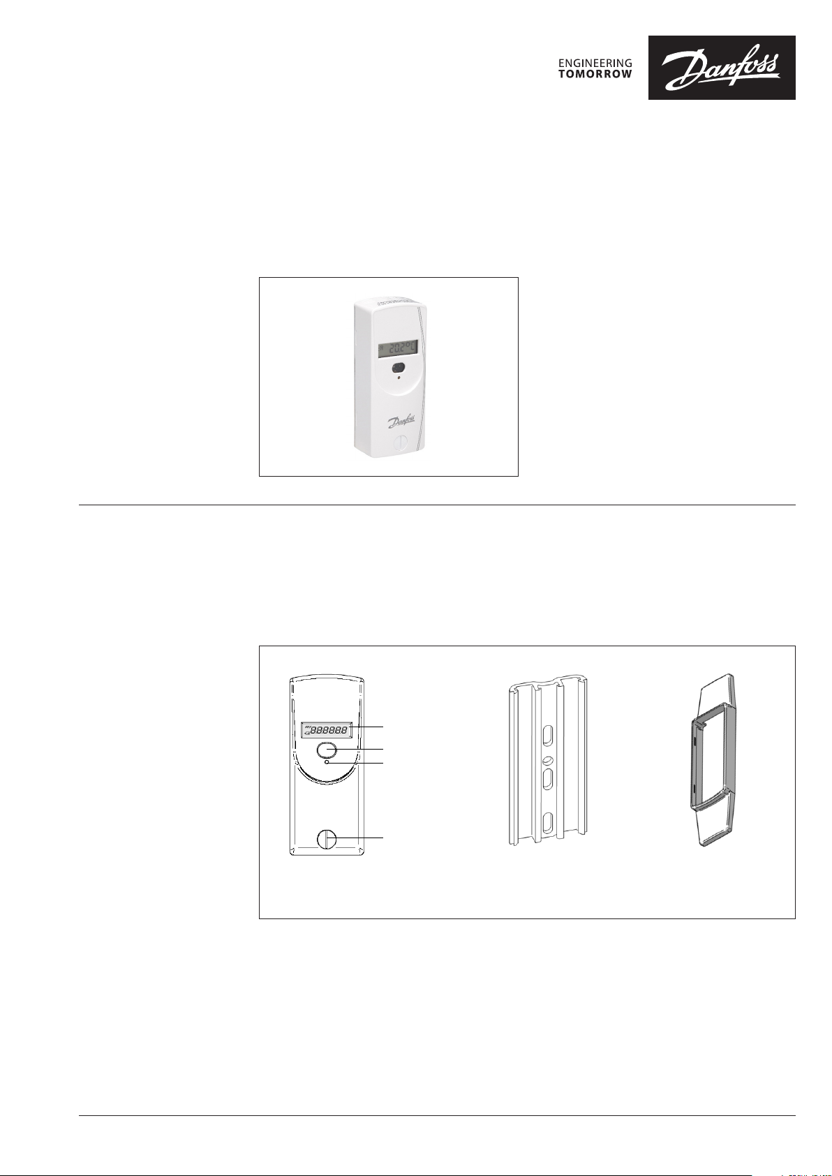
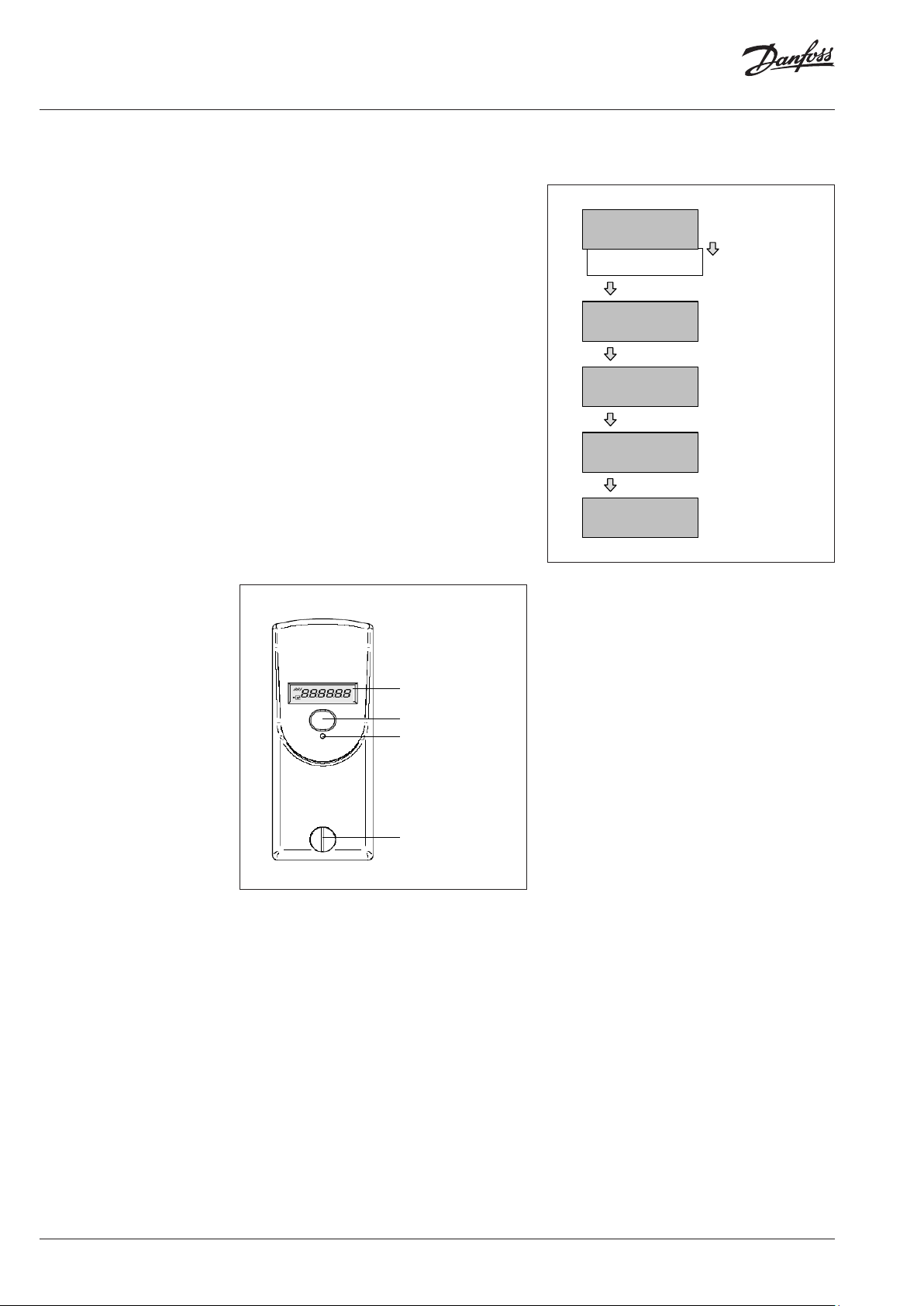
LC-Display
Optical Interface
Push Button
Seal
Electronic Heat Cost Allocator
SonoHCA
1 Specification
1.1 General Description
1.1.1 Type
1.1.2 Design
The heat cost allocator consists of a
microprocessor, a lithium battery, two
temperature sensors, a heat conducting
aluminium back plate, a multi-functional display
and a plastic housing.
The measuring circuit consists of the
temperature sensors, the analogue-digital
The electronic heat cost allocators SonoHCA
operate with the double sensor principle. The
device has been developed and approved
in accordance with the European Standard
EN 834 :2013.
conversion, the reference resistance for
standardising the measuring transformation and
the microprocessor for accessing the radiator
heat output. During each measuring the circuit
tolerances are eliminated with a reference
resistance and the heat cost allocator carries out
an automatic self-test.
Standard aluminium back plate
for nearly all existing bolts with
common dimensions and mounting
possibilities – thus easy installation
© Danfoss | 2019.05 VI.SH.R1.02 | 1
Snap-on blind to cover
colour shadows for
increased aesthetics
Page 2
Installation Guide SonoHCA
1.1.3 Characteristics
1.1.4 Display
• Measuring by two temperature sensors,
radiator and ambient temperature sensor
(NTC-resistor).
• Unit scale or product scale.
• Recording of cumulated heat consumption on
the annual set day.
• Recording of 144 monthly values and 18
half monthly values for cumulated heat
consumption.
• Recording of 18 monthly values for the
maximum radiator temperature.
• Optical interface for the readout of the data
and programming
• The radio module comprises a unidirectional
radio transmitter.
Two telegrams: short telegram, OMS
compliant and long telegram for Walk-by
reading.
• User-friendly operation by push button.
• 6-digit and high-contrast LCD display.
• Automatic commissioning during the
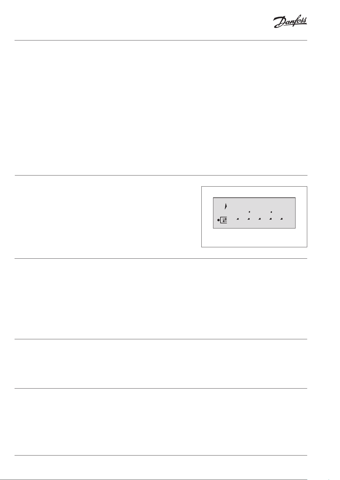
The heat cost allocator has a LCD-display with 6
large main digits on the right and 2 smaller digits
on the left as well as two special symbols and
one communication indicator. The main digits
are separated by four decimal points. Please find
the display segments:
mounting on the aluminium back plate
(available when ordering).
• Check code for postcard mail-in method
• Possibility to connect a remote sensor on each
version of heat cost allocator. The remote
sensor will be automatically detected by the
heat cost allocator.
• Remote sensor version with 2 m cable.
• Standard aluminium back plate for nearly
all existing bolts with common dimensions
and installation possibilities – thus easy
installation (no cutting and welding of bolts
necessar y).
• Snap-on blind to cover colour shadows for
increased aesthetics.
• Safe operation and fraud/manipulation
detection.
• Lithium battery with a capacity of up to 10+1
year.
• Meets EN 834:2013.
88
888888
1.1.5 E lec tronics
1.1.6 Optical Interface
Normally, the heat cost allocators are supplied
with switched-off LCD-display. On request, the
heat cost allocators can also be supplied with
permanent LCD- display.
The device has an electrical circuitry with
an 8-Bit-CMOS-micro controller of the latest
generation STM8L with extremely low current
consumption operating at a voltage as from
1.8 V.
The temperature measuring circuit with
automatic self-calibration measures the
discharging time of a capacitor. The accuracy
of the measuring circuit is independent of the
supply voltage.
With a standardised optical probe the
consumption and configuration values can
be transferred directly to a computer. All
consumption values can be readout over the
optical interface and over radio. The data are
Display with all active segments
For SonoHCA it is possible to plug the connector
of the remote sensor to an interface inside the
heat cost allocator. Refer to chapter 2.3 Mounting
the Remote Sensor.
Once equipped with a remote sensor, the heat
cost allocator will only work for an application
with remote sensor.
Remote sensor version with 2 m cable.
transmitted in M-bus-format acc. to EN136757-3.
Authorised personnel can alter the configuration
of the device over the optical interface with an
optical probe.
1.1.7 Radio Transmission
wM-Bus
2 | VI.SH.R1.02 © Danfoss | 2019.05
The radio heat cost allocator features a
transmitter circuit in the 868 MHz band with
integrated antenna.
This radio module comprises a unidirectional
radio transmitter which is used to transfer data
according to the wM-Bus (EN 13757-4) radio
communication protocol and in compliance with
the OMS (Open Metering System) Release V3.0.1.
• Please refer to chapter 1.7.4 Operation Mode
for Radio wM-Bus (SonoHCA) for the radio
reading range.
Page 3
Installation Guide SonoHCA
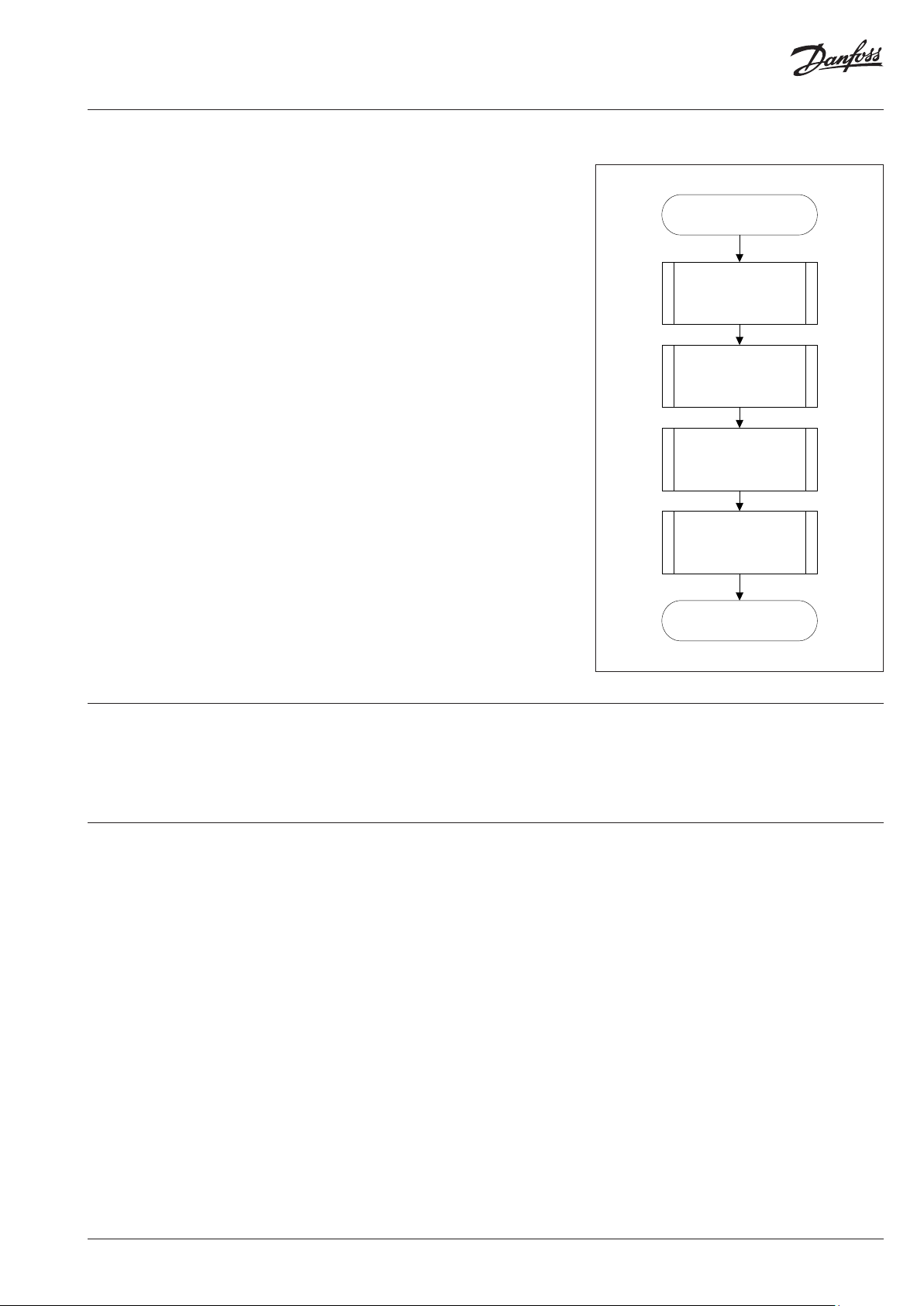
Start of cylce
Measuring and
calculation of the
temperature
Calculation of the
new consumption
value
Update time and
date
End of cycle
Update display
1.2 Operating mode
1.2.1 Cycle Time
SonoHCA operate in a cycle of 4 minutes. Most
of the time, the device is in sleeping mode. Every
4 minutes the device is set into operation and
operates according to the adjoining diagram.
The clock-pulse generator is a counter which is
completely independent from the rest of the
program. This counter is designed in a way so
that it is impossible to stall the cycle or to skip
one or more cycles.
Each cycle follows the adjoining diagram.
The measuring and calculating processes are
explained in detail later.
The tasks carried out during one cycle are taking
approx. 100 ms. This means that the device is in
sleeping mode more than 99.8 % of the time. It
can be set into operation between two cycles
over the optical probe or by pushing the button.
In this case it carries out the requested task and
then returns to sleeping mode.
In case an optical probe is connected or the
button is pushed during the course of the cycle,
the respective value is readout at the end of the
cycle.
The button can be pushed for an indefinite
period of time and the optical probe can be
left in its position since the normal function of
the device is not impaired by an influence from
outside.
1.2.2 Double Sensor real temperature, measured by the ambient
1.2.2.1 Heat Accumulation
Mode
For the double sensor version basically the
same specifications apply as for the single
sensor version with start sensor. However,
for calculating the room temperature the
In order to avoid faulty measuring due to heat
accumulation (e.g. in case the radiator is hidden
by panels), the device switches from a defined
ambient temperature (e.g. 28 °C) to the one
temperature sensor (corrected via the
corresponding radiator-dependent „K
is used as the basis.
sensor mode and calculates with an ambient
temperature of 20 °C.
-value“),
air
VI.SH.R1.02 | 3© Danfoss | 2019.05
Page 4

Installation Guide SonoHCA
NTC
1.2.3 Comparison of the
Measuring Principles
1.2.4 Temperature
Measurement and
Calculation
1.2.4.1 Measuring of a
Resistor, Principle
Double sensor measuring principle
For heating systems with tm
≥ 35 °C
min
The heat cost allocator calculates with a variable
reference temperature T
air temperature
Application:
Double sensor devices are used in areas where
precise measuring of the ambient temperature
is necessary and/or in low temperature heating
systems.
Radiators which are covered or blocked by
fixtures are detected automatically by the
double sensor system which then switches over
internally to the single sensor mode.
The temperature is measured with an NTC –
resistor. For the resistance measurement the
discharging time of the capacitor is measured.
The measurement is carried out as follows:
1. Charging of the capacitor
2. Discharging of the capacitor through the
resistance which is to be measured. At the
same time a 16+1 bit-timer starts with the
discharge to measure the discharging time
3. As soon as the voltage on the capacitor
terminals reaches a certain value, an interrupt
is induced and the timer stops. At the same
time the discharging of the capacitor is
stopped as well.
Within one billing unit, only one measuring
principle (either single sensor measuring
principle with start sensor or double sensor
measuring principle) can be used. Mixed
fitments or the use of different types of
devices in the same billing unit is therefore
also not allowed.
The processes for determining the K-value for
the single sensor device with start sensor and the
double sensor device are identical. It is only the
measuring principle that is different.
After the three mentioned stages, the timer
provides a 16-bit-value which corresponds to the
discharging time of the capacitor through the
resistance which is to be measured. In case the
resistance is known (reference resistance), the
constant ratio between discharging time and
resistance can be assessed.
1.2.4.2 Calculation of
the Value of an Unknown
Resistance (e.g. sensor
resistance)
1.2.4.3 Measuring of
the Radiator and Ambient
Temperature
The capacitor C is loaded at constant current. The
interrupt at the end of the discharge is triggered
by the same threshold voltage (a fraction of the
discharge voltage). If these two conditions are
met, the dis-charge time is directly proportional
to the resistance. With a reference resistance R
whose exact value is known, it is now possible to
ref
calculate the unknown resistance value Rx with
The following measurements are carried out
during one cycle:
1. Measuring of the reference resistance R
2. Measuring of the ambient temperature
sensor NTC
3. Measuring of the radiator temperature
sensor NTC
A
R
ref
The measuring values are calculated with the
following formula:
t
NTC
A R
R TC
= ⋅ = ⋅ N
A
t
ref
ref R
t
NTC
R
ref
t
ref
the following equation:
tRt
ref
= ⇒ = ⋅
R
refXX
From this equation the self-calibration of the
converter can be derived, which is given by
t
X
R
R
X
ref
t
ref
measuring the discharging time through the
reference resistance.
The reference resistance value is defined ex
works with a tolerance of 0.5% with 50 ppm.
The reference resistance features an excellent
temperature and long-term stability.
The capacitor value and the threshold voltage
have to remain stable over the whole cycle.
However, they can vary at the medium- or long
term without causing any failures because the
self-calibration of the con-verter is repeated
in every cycle while measuring the reference
resistance.
4 | VI.SH.R1.02 © Danfoss | 2019.05
Page 5
Installation Guide SonoHCA
= ∗∫ (
−
60
)
1.33
1.2.5 Calculation of the
Displayed Consumption
Value
1.2.6 Start of Counting
The value displayed on the heat cost allocator is
calculated as follows:
Double sensor device
Explanation: TH Temperature of the radiator surface in [°C]
TA Ambient temperature in [°C]
Q Displayed consumption value, without unit
Kc Factor that carries back the ΔT measured at a normalized value
Kq Factor Kq is a numerical value of the nominal power of the radiator
stated in [kW].
Unit scale: Kc = 1 and Kq=1.
Product scale: Kc <> 1 and Kq <> 1
The updating (increment) of the consumption
value is carried out under the following
conditions:
During winter period (heating period):
(TR ≥ 25 °C)
Or
(TR ≥ 20 °C ) E (TR - TA ≥ ΔT
MIN
)
During summer period (off heating period):
(TR ≥ 35 °C)
Or
(TR ≥ 20 °C ) E (TR - TA ≥ ΔT
MIN
)
Explanation:
TR Radiator temperature
TA Ambient temperature
ΔT
Minimum temperature difference
MIN
between radiator and room
3K for standard device (winter heating
period standard setting)
4K for remote sensor device (summer
heating period standard setting)
Note:
The thresholds of starting (25°C et 35°C) are
indicative values. These temperatures of starting are
adjust-ed according to the needs and specificities of
the customer.
VI.SH.R1.02 | 5© Danfoss | 2019.05
Page 6
Installation Guide SonoHCA
LC-Display
Optical Interface
Push Button
Seal
1.3 Display and
Additional Functions
1.3.1 The Menu
Sequences of the Digital
Display
The menu sequences
Ex factory all menu sequences are activated.
With a software the order of the menu
sequences 1 - 15 can be changed in any order.
However the order within the individual menu
sequences 1 – 15 cannot be changed. It is also
possible to hide individual menu sequences so
that they are not visible to the end-user.
When reading out over the optical interface
or via radio the complete set of data is always
readout and transferred.
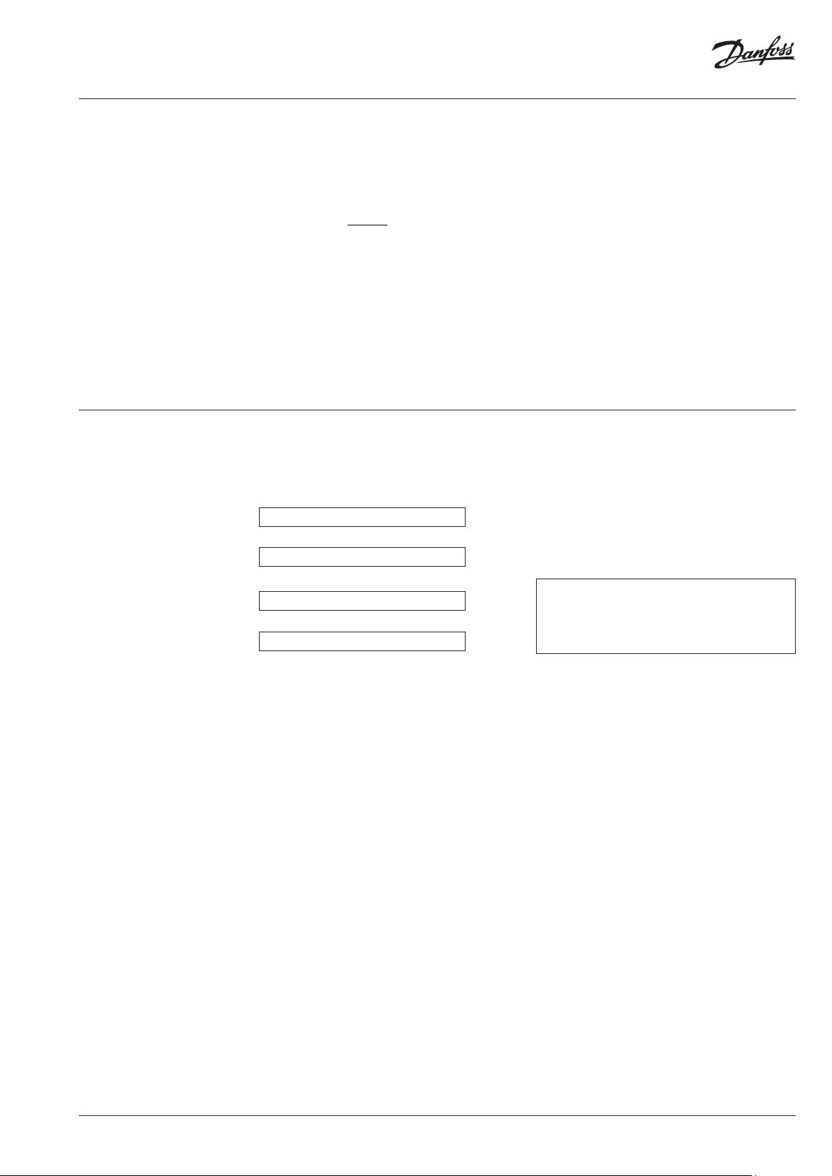
Operation of the Push Button
When pushing the button briefly the digital
display always goes to the next menu sequence.
When pushing the button in one menu sequence
for 2 seconds the individual values within the
selected menu sequence can be accessed. When
the last value within one menu sequence has
been displayed, the 1st position will be displayed
by pushing the button again.
If the button is not pushed for 2 minutes,
the digital display returns to the cumulated
consumption value.
Consumption value
36 Monthly Values
Short key press
Current time
Short key press
Current date
Short key press
Set Day value
Short key press
Radiator temperature
Display position 1
Long key press
Display position 2
Display position 3
Display position 4
Display position 5
6 | VI.SH.R1.02 © Danfoss | 2019.05
Page 7

Installation Guide SonoHCA
002345
000000
54321
290515
1.3.2 The Digital
Displays
During normal operation the display is
deactivated and can be activated by pushing the
button.
If the button is not pushed, the display will be
active for 2 minutes only.
On request, the heat cost allocator is also
available with permanent display 24h/24h or
with a rolling menu displayed.
Consumption Value Unit Scale
u
002345
Consumption Value Product Scale
Display in Euro
Eu
43725
On the display of the heat cost allocator with
unit scale an index u for unit is shown on the left
side. If the index u is not displayed, the heat cost
allocator is equipped with the product scale.
When commissioning the device this value is
000000. When reaching the value 999999, the
counting restarts automatically at 000000.
The heat cost allocators have the option to
display the heating cost in Euro.
The cost in Euro indicated on the display is only
approximate and is based on historical values
from the previous year.
The displayed cost does not necessarily
represent the charges to be paid.
Manufacturer and supplier decline any claims
concerning the use and interpretation of the
indicated values.
This option can be activated via a software.
Set day Value
Sd
002345
Sd
Check code
CC
Time
14h27
Date
With the index Sd the consumption value
recorded at midnight of the set day is displayed.
The consumption value recorded can be in unit
scale or in product scale. It’s depending of the
unit setting.
If a new device has not yet reached the
programmed set day, 000000 is displayed.
With the index CC the check code for the
plausibility check of the manual readout is
displayed.
The current time (always winter time).
The current date of the heat cost allocator.
VI.SH.R1.02 | 7© Danfoss | 2019.05
Page 8

Installation Guide SonoHCA
2905--
020615
1568
32
002345
002345
158
123456
1.3.2 The Digital
Displays (continuous)
Set Day
Sd
Date of Opening of the Device
od
290515
Data messa in funzione
Cd
Cumulated Duration of the Opening of the
Device
du
It is possible to program an annual set day on
which the cumulated consumption value as
well as the maximal radiator temperature are
recorded.
With the index Sd the programmed annual set
day is displayed.
Each heat cost allocator is equipped with a
manipulation protection which detects an
unauthorised opening of the device after
installation to the radiator. The date of the last
opening of the device is recorded and displayed
with the index od.
With the index Cd the commissioning date is
displayed, i.e. the date on which the device has
been activated by pushing the button or during
the mounting of the aluminium back plate if the
function automatic commissioning is set.
With the index du, the cumulated duration in
minutes during which the device was opened
is detected. This display turns up only after
commissioning in case the heat cost allocator
was opened or removed.
Fraud Counter
fc
Identification Number
15
Running Hours
rh
Monthly Values
01
36
This value indicates how many times the fraud /
manipulation was activated.
With the index an 8 digit identification number
is displayed. Ex factory the serial number is
identical with the identification number. The
first two digits of the identification number are
the two small digits on the left upper side of the
digital display.
With the index rh, the running hours is displayed.
This value can be compared to the battery use
duration.
The cumulated consumption values are recorded
automatically at midnight on the last day of each
month.
Number of monthly values: 36
The small digits on the upper left side show
the number of previous monthly values. Digit
01 stands for the recent full month and digit 36
stands for the least recent month. All monthly
values are set to 000000 when the device is
commissioned.
Note:
Short telegram, OMS compliant: no monthly values transmitted via radio telegram.
Long telegram for Walk-by reading, the first 18 monthly values transmitted via radio telegram.
8 | VI.SH.R1.02 © Danfoss | 2019.05
Page 9

Installation Guide SonoHCA
002345
002345
359 'c
359 'c
Fir003
1.3.2 The Digital
Displays (continuous)
Half Monthly Values The cumulated consumption values are recorded
41
58
Note:
Short telegram , OMS compliant and long
telegram for Walk-by reading: no half monthly
values transmitted via radio telegram.
Radiator Temperature
tr
automatically at midnight on the 16th of each
month.
Number of monthly values: 18
The small digits on the upper left side indicate
the number of half monthly values. Digit 41
stands for the recent half monthly value and digit
58 for the least recent half monthly value. All
half monthly values are set to 000000 when the
device is commissioned.
With the index tr the current radiator
temperature is displayed.
689 'c
Ambient Temperature
tA
With the index tA the current ambient
temperature is displayed.
257 'c
Maximum Radiator Temperature of the
Current Heating Period
With the index ΠΨ the maximum radiator
temperature of the current heating period (since
the Set Day) is displayed.
Maximum Radiator Temperature of the
Previous Heating Period
Sd
Monthly Value for Maximum Radiator
Temperature
327 'c
01
327 'c
18
327 'c
Software Version
With the index Sd the maximum radiator
temperature of the previous heating period
(before the Set Day) is displayed.
With the index ΠΠ the maximum radiator
temperature of the currently month is displayed.
Number of monthly values: 18
Recording of 18 monthly values for the maximum
radiator temperature.
The small digits on the upper left side show
the number of previous monthly values. Digit
01 stands for the recent full month and digit 18
stands for the least recent month.
All monthly values are set to 000000 when the
device is commissioned.
On the right side the software version x.x.x of the
heat cost alloca-tor is displayed.
Measuring Principle The index -- or FF indicates the type of the
--
radiator sensor:
-- = Standard device, compact sensor.
FF = Remote sensor device, remote sensor.
2 SENS = double sensor device.
VI.SH.R1.02 | 9© Danfoss | 2019.05
Page 10

Installation Guide SonoHCA
Short
1.3.2 The Digital
Displays (continuous)
1.3.3 Rolling Digital
Display
Segment Test
88
888888
Error Message
err 2
wM-Bus mode
lon6
SonoHCA also feature the possibility of a rolling
display 24h/24h.
With a software, it is possible to individualize the
rolling display.
Up to 15 parameters can be chosen optionally
from the list below. These parameters can be
combined in any order and are then shown on
the rolling display.
• Consumption value
• Time
• Date
• Set Day
• Set Day value
• 36 monthly values for cumulated
consumption
• 18 half monthly values for cumulated
consumption
• Radiator temperature
• Ambient temperature
• Identification number
• Maximum radiator temperature of the
previous heating period
• Maximum radiator temperature of the
current heating period
• 18 monthly values for the maximum radiator
temperature
• Error code
• Manipulation protection: storing of the
duration of the last manipulation with
date and the accumulated duration of all
manipulations in minutes
• Fraud Counter
• Segment test
• Software version
• Running hours
• Commissioning date
• Measuring principle, single sensor device
with start sensor or double sensor device
• Short or long telegram for radio wM-Bus
Segment test of the display.
If an error is detected, Err is displayed in the first
display sequence with the corresponding error
message.
Telegram defined into heat cost allocator.
Type of telegram must be defined when
ordering.
Short telegram (Short) used.
Long telegram (LonG) used.
The duration of the display of the values can be
chosen individually between 1 - 30 seconds.
Example:
Order and duration of display
• Pos. 0 : Error (parameter ex factory, cannot
be changed) [5 s]
(only displayed in case of an error message)
• Pos. 1 : Time [1 s]
• Pos. 2 : Segment test [5 s]
• Pos. 3 : Consumption value [10 s]
• Pos. 4 : Set Day [1 s]
• Pos. 5 : Set Day value [8 s]
• Pos. 6 : Monthly value [5 s]
• Pos. 7 : Blank (therefore no display).
• Pos. 8 – Pos 15 : Blank (therefore no display. It
is not necessary to occupy all positions)
The rolling display can also be deactivated by a
software, i.e. the device operates as in standard
menu mode except that only these values and
the values of the corresponding sub-menus that
have been defined in the rolling menu can be
displayed by pushing the button. After 2 minutes
during which the button has not been pushed,
the display goes out.
10 | VI.SH.R1.02 © Danfoss | 2019.05
Page 11

Installation Guide SonoHCA
1.3.4 Communication
Indicator and Measuring
Indicator •
1.3.5 Real Time Clock
and Calendar
The communication indicator displays if the heat
cost allocator is currently making a calculation
and/or if it communicates internally or externally
over the optical.
u
123456
u
123456
u
123456
u
123456
The device has a 24 h real time clock and a
calendar. However, the change from summer
to winter time is not taken into account. The
calendar is programmed until December 31
If the current date and time have to be updated over the optical inter face or via radio, it is necessary
to check the date of the computer first. Date and time of the device aim at those of the computer. If
the reading/programming device (computer/PDA/ Smart Phone) has a wrong time, this time will be
programmed into the heat cost allocator and suddenly no longer be reached at the usual time, because
the time of the heat cost allocator possibly is shifted by several hours.
If the arrow of the communication indicator
points inwardly internal communication takes
place over the optical.
If the arrow of the communication indicator
points outwards external communication takes
place over the optical.
If the frame of the communication indicator
appears the heat cost allocator has detected a
wake-up signal.
If the point indicator appears the heat cost
allocator is carrying out a measuring or a
calculation.
2099, including all leap years. The real time clock
as well as the date of the heat cost allocator can
be readout over the optical interface or via radio
and if necessary be updated.
1.3.6 Readout
The current and monthly values recorded by
the heat cost allocator as well as several other
parameters can be readout over the optical
interface or also over radio.
The following parameters are transmitted:
Optical Interface:
• Identification number (information in
header)
• Date and time
• Consumption value
• Set Day
• Set Day value
• Maximum radiator temperature of previous
heating period
• 36 monthly values and 18 half monthly
values for cumulated consumption
• 18 monthly values for the maximum radiator
temperature
• Rating factor K
• Rating factor K
C
Q
• Current radiator temperature
• Current ambient temperature
• Maximum radiator temperature of the
current heating period
• Manipulation protection:
- Duration of the manipulations
- Date of the last manipulation
- Manipulation counter
• Error code
• Firmware version
• Commissioning date
• State of parameters
• 36 half monthly values for the average
ambient temperature
VI.SH.R1.02 | 11© Danfoss | 2019.05
Page 12

Installation Guide SonoHCA
1.3.6 Readout
(continuous)
1.3.7 Check Code
The following parameters are transmitted by
SonoHCA via 868MHz Radio (wM-Bus):
Short telegram, OMS compliant:
• Identification number (information in
header)
• Date and time
• Consumption value
• Set Day
• Set Day value
• Error code
• Current radiator temperature
• Current ambient temperature
• State of parameters
Long telegram for Walk-by reading:
• Identification number (information in
header)
• Date and time
• Consumption value
• Set Day
• Set Day value
• 18 monthly values for the cumulated
consumption
A special additional feature of the electronic heat
cost allocator is the check code function for the
postcard mail-in method.
With especially developed algorithms a 5 digit
check code is generated out of several device
data. With this check code the values stated on
the postcards mailed-in by tenants can be cross
checked.
• Rating factor K
• Rating factor K
• Current radiator temperature
C
Q
• Current ambient temperature
• Maximum radiator temperature of the
current heating period
• Maximum radiator temperature of the
previous heating period
• Manipulation protection:
- Duration of the manipulations
- Date of the last manipulation
- Manipulation counter
• Error code
• Firmware version
• Commissioning date
• State of parameters
AES 128 bits encryption is available for all
versions.
For this check, the following parameters are
required:
• Identification number
• The date
• The current consumption value
• The check code
For the verification of the check code SonoHCA
places all necessary tools (programs, formulas) at
the disposal of the authorized personnel.
1.3.8 Change of Battery
The battery of the heat cost allocator is soldered.
The lithium battery is not rechargeable. A change
of battery is not planned. Therefore the heat cost
allocators have to be replaced after 10 years.
Disposal
It is mandatory to dispose of the heat cost
allocator environmentally friendly or to return
it after use to the manufacturer for appropriate
disposal to ensure that the components are
recycled in accordance with the battery and
electronic scrap regulations. Should you do the
disposal yourself please get information from
your local authority on the recycling possibilities
12 | VI.SH.R1.02 © Danfoss | 2019.05
Page 13

Installation Guide SonoHCA
1.3.9 Protection against
Outside Influences
1.3.9.1 Seal
The heat cost allocator is closed with a seal which
cannot be removed without damaging it. Thus it
is impossible to open the device unnoticed.
After installation, the electronic part of the
device is no longer accessible. The digital display,
the push button and the optical interface are
covered by a sight glass. It is impossible to access
the inside of the device through these openings
without damaging the sight glass.
1.3.9.2 Electronic Detector
in Case of an Opening of the
Device
1.4 Special Functions
1.4.1 Suppression of
Summer Counting
1.4.2 Annual Reset of the
Consumption Value
1.4.3 Unit Scale and
Product Scale
The electronic detector detects unauthorised
opening, removing and closing of the heat cost
allocator. As soon as the housing of the heat
cost allocator is opened and/or removed, the
electronic detector triggers an error message.
The period during which summer counting is
suppressed can be programmed by the software.
If the heat cost allocator is in the period of
summer counting suppression, consumption
The function of the annual reset of the
cumulated consumption value can be
programmed by the software over the optical
interface. One of the following options can be
chosen for the reset:
• Set Day
• Never
For the heat cost allocators SonoHCA, distinction
is made between the unit scale and the product
scale.
If heat cost allocators are used with the same
scale on all radiators, this scale is called unit
scale. The display values are the same on the
different radiators if the heat cost allocators are
The duration of each opening is counted,
cumulated and only the last date of opening
recorded.
measuring is deactivated. If an automatic
readout is carried out during this period the
temperatures can be read anyway since the
temperature measuring is still active.
Please note that only the cumulated
consumption value is reset. All other values are
not reset.
exposed to the same temperature for the same
period of time.
The evaluation of the display values is carried
out arithmetically with the rating factors of
the calculation software to receive the final
consumption values.
1.4.3.1 Advantages of the
Unit Scale
• Easy and quick installation of the heat cost
allocator, no programming necessary
• Possible errors by doing the scaling on site
are avoided due to allocation by experts
on site. The overall rating factor total (K
calculated directly in the heat cost allocator
and thus the consumption value is displayed
immediately.
Tota l
) is
With the product scale, the radiator rating data
are programmed in the heat cost allocator
1.4.3.2 Advantages of the
Product Scale
• The actual consumption of each consuming
point within one billing unit can be
compared easily and quickly on site
1.5 Parameterization ‘’installer’’ password ex-factory of the heat cost
A software allows the parameterization over the
optical interface.
To protect heat cost allocator against fraud, a
allocator is ''56781234'', and may be changed by
the user.
password has been integrated into the products,
therefore also in the software. The default
VI.SH.R1.02 | 13© Danfoss | 2019.05
Page 14

Installation Guide SonoHCA
1.6 Error
1.6.1 List of Errors
1.7 Radio Standby –
SonoHCA
The heat cost allocator displays an error message
with the 3 letters “ Err. ” and a code. If several
errors occur at the same time, the different codes
are added together.
The error is displayed in the first position of the
display menu. It will still be possible to select
all the other display menus by pressing the
• Err. 1 Manipulation (fraud)
• Err. 2 Measuring error
• Err. 32 Push button constantly pushed
• Err. 64 Measured temperature not within
temperature range (0...105°C; 0...120°C
remote sensor)
In order to achieve a user-friendly and powersaving radio standby, the radio heat cost
allocator features the following different
operating modes:
navigation button. If the navigation button is
no longer pressed for a period of 2 minutes, the
error code will automatically appear again in the
first position of a display menu.
Display of an error automatically disappears
when the error is no longer present.
* : SLEEP information w ill be displayed by
pushing the push bu tton.
Transition from sleeping mode to installation mode is achieved by two different ways:
1. Pushing the push button once the heat cost allocator is mounted on the aluminium back plate.
2. An automatic detection during the mounting on the aluminium back plate. This function must be
specified at the order.
1.7.1 Sleeping Mode Transition from sleeping to installation mode is
Ex factory the radio heat cost allocator is in
sleeping mode, but the internal clock and the
date are running.
Current consumption is reduced to a minimum
since no measuring and no calculations are
carried out. Only the optical communication
achieved by pushing the button once the heat
cost allocator is mounted on the aluminium back
plate or by an automatic commissioning during
the mounting on the aluminium back plate (must
be specified when ordering).
interface is available.
14 | VI.SH.R1.02 © Danfoss | 2019.05
Page 15

Installation Guide SonoHCA
1.7.2 Installation Mode
1.7.3 Operation Mode
for Radio wM-Bus (SonoHCA
868MHz Radio)
1.7.3.1 Readout over
the short telegram
(OMS compliant)
u
123456
The • symbol indicates that the heat cost
allocator is in installation mode.
During the installation mode all functions of the
radio heat cost allocator are carried out.
• For heat cost allocator, an installation
telegram is activated during the installation
phase. Data are transmitted each 30 seconds
(short and long telegram) till at the end of
the second day at midnight.
If heat cost allocator is removed from the aluminium back plate during the installation mode, the heat cost
allocator switches to the sleeping mode.
With this operating mode, the heat cost allocator
SonoHCA transmits data:
• Transmission interval each 120 seconds
(minimum)
• Radio reading, 24h/24h
The radio heat cost allocator switches
automatically into operating mode at the end of
the second day at midnight.
1.7.3.2 Readout over the
long telegram for Walk-by
reading
1.7.4 Short Telegram or
Long Telegram for Radio
wM-Bus (868)
2. Installation
2.1 Introduction
With this operating mode, the heat cost allocator
SonoHCA transmits data:
• Transmission interval each 120 seconds
(minimum)
• Radio reading and periods, 12h per day
(programmable), 5days/7days
Type of telegram must be defined when
ordering. There is no possibility to select the type
of telegram directly on the heat cost allocator.
To guarantee the proper functioning of the heat
cost allocator, it is of great importance that it is
installed by an expert. On one hand, a constant
heat transfer between radiator and heat cost
allocator has to be guaranteed. On the other
hand, the installation of the heat cost allocators
on a large variety of radiator types should be as
easy as possible.
The installation can be carried out in two
different ways.
• The standard device is installed directly on
the radiator.
• For the wall-mounted version the remote
sensor is installed on the radiator and the
heat cost allocator is wall-mounted.
For the installation of the heat cost allocators,
special fastening-parts kits are available. To
avoid faulty installation, we also recommend
reading the Kc-data in the data base prior to the
installation.
The heat cost allocator is an electronic device
which – like all other similar devices – has to
be handled with care. It is sensible to electric
discharge and contacting certain areas of the
PCB. Electric discharge can destroy the device
or – even worse - damage it in a way that it fails
after an indefinite period of time.
For this reason it is essential in any case to
avoid contact with the PCB.
VI.SH.R1.02 | 15© Danfoss | 2019.05
Page 16

Installation Guide SonoHCA
2.2 DIN Standard
Requirements for the
Installation
2.3 Mounting the
Remote Sensor
• Heat cost allocators can be installed
in heating systems where the mean
temperature is between the upper
operating temperature limit t
lower operating temperature limit t
and t
are stated in the technical data, see
min
chapter 4 Technical Data)
and the
max
min
(t
• The installation of the devices has to be
durable and avoid manipulations.
• The devices have to be installed in a place
where sufficient correlation between the
displayed value and the heat output of the
radiator is given over a maximum operating
range.
• Within a billing unit (in case of predistribution of the energy consumption:
within a users’ group) only heat cost
allocators of the same manufacturer and
For each version of heat cost allocator, it is
possible to plug the connector of the remote
sensor into an interface inside the heat cost
allocator.
The remote sensor will be automatically
detected by the heat cost allocator.
max
the same type with identical rating systems
may be used. Each device type has to be
identifiable as such.
• Combinations of radiators and heat cost
allocators with a measured value of c > 0.3
in basic condition are not permitted. In
exceptional cases c-values of up to 0.4
are permitted within a billing unit if the
concerned heating surface does not exceed
25 % of the overall heated surface or if the
mean ambient temperature is above 80 °C.
Heat cost allocators may only be installed to
radiators where the c-value is known at the
time of billing.
Once equipped with a remote sensor, the heat
cost allocator will only work for an application
with remote sensor.
Remote sensor version with 2 m cable. The cable
includes a stopper-knot.
Insert the remote sensor cable into the groove
Return the heat cost allocator and plug the connector of the
remote sensor into the interface inside the heat cost allocator.
Proceed to the commissioning of the heat cost
allocator on the aluminium back plate. Take care
not to stick the cable.
Respect the color code of the radiator sensor and
the remote sensor:
• Heat cost allocator SonoHCA: the
radiator sensor and the remote sensor are
manufactured with a white color.
provided up to the slot of housing.
Place the stopper-knot inside the housing. The
knot will avoid any traction on the connector.
During the commissioning of the heat cost
allocator on the aluminium back plate, there are
2 possibilities to turn on the heat cost allocator:
1. By an automatic commissioning during the
mounting on the aluminium back plate.
See chapter 3.1 Automatic commissioning
during the installation
2. By pushing the push button.
See chapter 3.2 Commissioning by pressing
push button.
Once equipped with a remote sensor, the heat cost allocator will only work for an application with remote sensor.
If the remote sensor is disconnected from the heat cost allocator, an error message will be displayed.
16 | VI.SH.R1.02 © Danfoss | 2019.05
Page 17

Installation Guide SonoHCA
2.4 General
Restrictions
2.5 Operating Range
2.6 Mounting and
Sealing
Electronic heat cost allocators cannot be used
with steam heating, floor heating, ceiling radiant
heaters, flap-controlled radiators and electrical
radiator.
In case of combined valve- and flap-controlled
radiators, the installation of an electronic heat
cost allocator is only permitted if the flap control
is dismounted or maintained in position „open“.
The SonoHCA heat cost allocators can be used
in heating systems with the following mean
heating medi-um temperatures:
For double sensor devices:
• 35°C…105° C for standard heat cost
allocators
• 55°C…120°C for wall-mounted heat cost
allocators (remote sensor)
After installation of the respective fasteningparts kit to the radiator, the heat cost allocator
can be mounted and sealed by the installer as
described below:
Convector heaters where the performance can
be altered by an electric blower as well as heat
towel racks with an electric heating cartridge
may only be equipped with an electronic
heat cost allocator if the additional electric
attachments are dismounted or shut down.
A heat cost allocator can be used in heating
systems where the suitability of the system is in
line with the operating conditions for which the
heat cost allocator has been approved.
The heat cost allocator is
placed at the upper end
of the aluminium back
plate. Move the heat cost
allocator down so that
the hooks in the housing
fit in the aluminium back
plate.
The heat cost allocator is
placed on the aluminium
back plate in the
direction of the arrow.
Push the seal preinstalled
by SonoHCA in the slot
of the housing, then
press until the seal click s
into the aluminium back
plate.
Now the heat cost
allocator can only be
opened by destroying
the seal.
VI.SH.R1.02 | 17© Danfoss | 2019.05
Page 18

Installation Guide SonoHCA
Automatic change
Pushing the push
SLEEP
3. Commissioning
3.1 Automatic
commissioning during the
installation
Ex factory the heat cost allocators are in the socalled sleeping mode. In this mode no measuring
is carried out and thus no consumption values
are calculated. Furthermore the digital display,
the radio communication options as well as the
device opening detection are deactivated. Only
Transition from sleeping to installation mode is
achieved by pushing the button once when the
heat cost allocator is mounted on the aluminium
back plate or by an automatic commissioning
during the mounting on the aluminium back
plate.
the optical communication interface is available.
The date and time are running in the
background.
After the commissioning and before leaving a new site, we recommend to per form a radio read out test and to
create an installation protocol, to ensure that all the radio communication between the heat cost allocators and
the radio central or radio modem was successful.
Once heat cost allocator is fixed with/against the
aluminium back plate, the LCD-display will show
Transition from sleeping to installation mode is
achieved automatically after 5 seconds:
the following message:
FF
SLEEP
The index FF indicates that the heat cost
allocator has recognized the remote sensor.
If the remote sensor is not detected by the
device, the index -- will be displayed.
FF
after 5 sec
SLEEP
The • symbol indicates that the heat cost
allocator is in installation mode.
u
123456
Installation ModeSleeping Mode
The index -- indicates also a standard device with
a compact sensor.
This message will be displayed during 5 seconds
and after that, the transition from sleeping mode
to installation mode will be done automatically.
Once installed on the back plate or the wall, the
heat cost allocator switches automatically from
the installation mode into the operating mode at
the second transition of midnight.
3.2 Commissioning by
pressing push button
Once heat cost allocator is fixed with/against the
aluminium back plate, the LCD-display will show
the following message:
FF
The index FF indicates that the heat cost
allocator has recognized the remote sensor.
If the remote sensor is not detected by the
device, the index -- will be displayed.
The index -- indicates also a standard device with
a compact sensor.
This message will be displayed during 2 minutes
before the LCD-display will switch off.
Transition from sleeping to installation mode
is achieved by pushing the push button during
3 seconds:
FF
button (3sec)
SLEEP
u
123456
Installation ModeSleeping Mode
The • symbol indicates that the heat cost
allocator is in installation mode.
Once installed on the back plate or the wall,
the heat cost allocator switches automatically
into operating mode at the second transition of
midnight.
18 | VI.SH.R1.02 © Danfoss | 2019.05
Page 19

Installation Guide SonoHCA
4. Technical Data
Measuring systems
For heating systems with tm
Calculation with variable ref. temperature T-air sensor
≥ 35 °C
min
Necessar y rating factors: KQ, KC, (KA, K T)
Optional scales Unit scale or product scale
Current supply 3 V-Lithium-battery
Life-span with 1 battery > 10 years
Display Liquid crystal display (LCD-display)
No. of displayed digits 6 digits (000000 ... 999999)
Sensor temperature range: 0 °C ... 120 °C
Exponent n = 1.33
Radiator – performance range 4 Watt ... 16.000 Watt
Design temperature range
(tm
… tm
min
)
max
Double sensor system
35 °C ... 105°C / 120 °C (compact- / remote sensor)
KC-values Rating fac tors see digital KC-data base
Models Compact device or remote sensor device
Set day Freely programmable
144 monthly values and 18 half monthly values for cumulated heat consumption, 18
Data storage:
monthly values for the maximum radiator temperature. Maximum temperature of
the current and previous year, all relevant consumption values
Self-test Before every measuring
Start of counting
Heating period 25°C – 4 0°C (programmable)
Off-heating period 25°C – 4 0°C (programmable)
Standard version Acc. to EN 834
Homologation acc. to H KV O: A1.0 2.20 15
DIN registry No. 291/08 E
Conformity CE
At 75% of the overall height of the radiator.
Standard mounting height
If the height of the radiator is less than (<) 470 mm, the heat cost allocator must
be installed at 50% BH. (in case of deviating mounting heights, please refer to this
manual and the digital KC-data base.
VI.SH.R1.02 | 19© Danfoss | 2019.05
Page 20

Danfoss S.r.l.
Heating Segment
Danf
Ciò vale anche per i prodotti già ordinati, a condizione che tali modiche possano essere appor
citati nel presente materiale sono di proprietà delle rispettive società. Danf
Installation Guide SonoHCA
•
heating.danfoss.it • +39 011 3000 511 • E-mail: info@danfoss.it
oss declina ogni responsabilità per eventuali errori contenuti in cataloghi, brochure o altra documentazione cartacea. Danfoss si riserva il diritto di modicare i propri prodotti senza preav viso.
oss e il logo Danfoss sono marchi registrati di Danfoss A/S. Tutti i diritti sono riservati.
tate senza rendere necessarie successive variazioni alle speciche già concordate. Tutti i marchi registrati
© Danfoss | DHS-SRMT/SI | 2019.0520 | VI.SH.R1.02
 Loading...