

Page 1
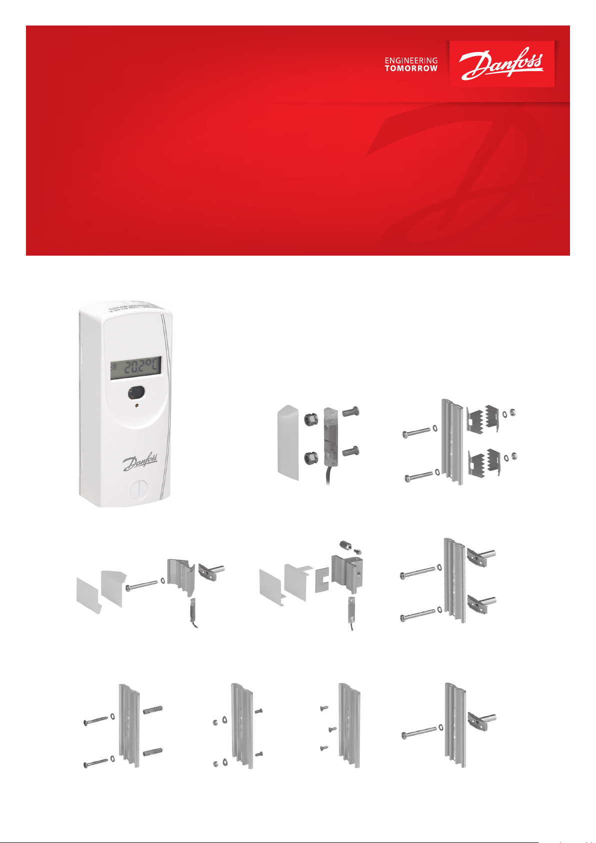
Operating Guide
SonoHCA
Fastening parts and mounting accessories
Page 2
Operating Guide SonoHCA - Fastening parts and mounting accessories
Table of Contents
1. Allocator Installation
Position – Standard
Installation
1 Allocator Installation Position – Standard Installation .......................................................... 2
2 Wall Mounting ............................................................................................................................. 4
3 Installation of Fastening Parts Kits ........................................................................................... 5
3.1 Installation to Sectional Radiator, direct mounting ................................................................................ 5
3.2 Sectional Radiator, wall mounting ................................................................................................................ 5
3.3 Installation on Folded Radiator ...................................................................................................................... 6
3.4 Folded Radiator, wall mounting ..................................................................................................................... 6
3.5 Installation to Panel Type Radiator ............................................................................................................... 7
3.6 Mounting of heat cost allocators with glue ............................................................................................... 8
3.7 Panel Type Radiator, wall mounting ............................................................................................................. 9
3.8 Installation to Panel-Type Radiator with Front Convection Plate ...................................................... 10
3.9 Bathroom radiator – Towel rails ..................................................................................................................... 10
3.10 Sectional Radiator wide .................................................................................................................................... 11
4 Overview mounting accessories ............................................................................................... 12
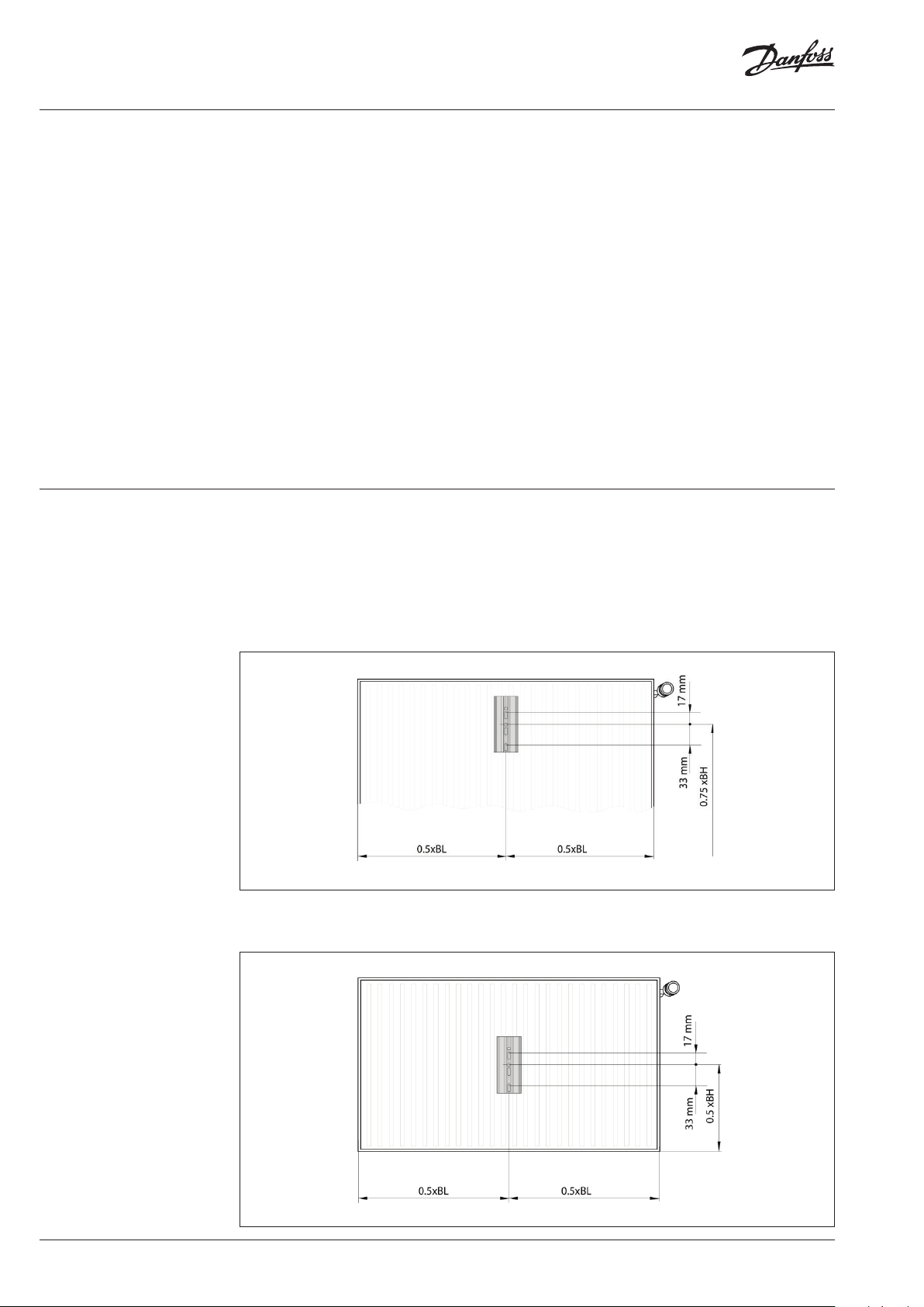
The installation position on the radiator is directly related to the type of radiator, its heating power
and the heat cost allocator. To guarantee the correct data collection, the heat cost allocators must be
installed and used in a certain position in accordance with requirements.
The radiator’s heat is transmitted directly via the installation back plate to the device’s temperature
sensor or to its remote sensor
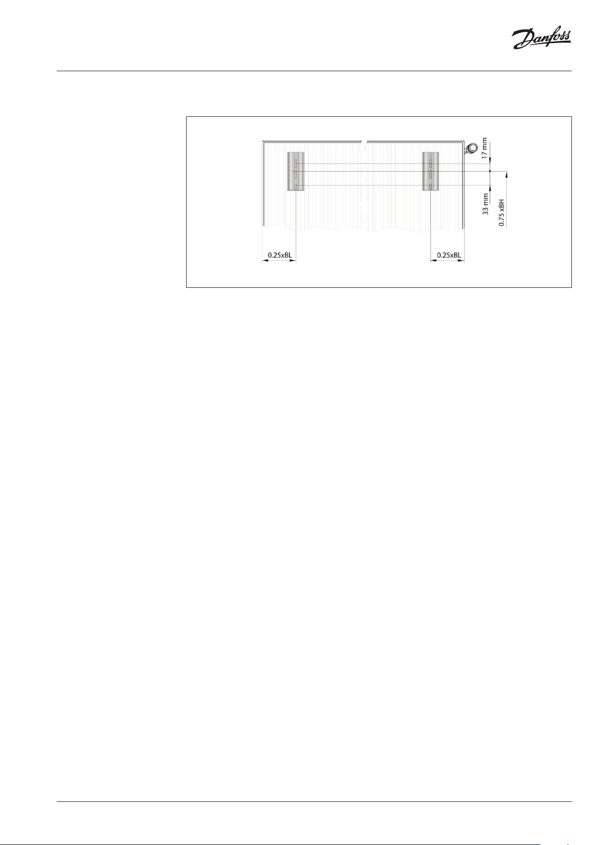
• The SonoHCA heat cost allocator is always installed in the centre of the overall length (0.5 x BL)
of the radiator, at a height of ¾ of the overall height (0.75 x BH) measured from the bottom.
• If the height of the radiator is less than (<) 470 mm, the heat cost allocator must be installed at
50% BH.
2 | AQ353735633516en-010101 © Danfoss | 2020.09
Page 3
Operating Guide SonoHCA - Fastening parts and mounting accessories
1. Allocator Installation
Position – Standard
Installation (continuous)
• If the height of the radiator is less than (<) 470 mm, the heat cost allocator must be installed at
50% BH.
General notes:
• The spacing for welding the M3 threaded bolts must be 5 cm. Before welding, the lacquer has
to be removed from the welding points. It must be ensured that the bolts are welded onto a
water-bearing area or a flute.
• Only use M3 bolts with a maximum length of 8 mm or there is a risk that the device will be
damaged.
• Welding to aluminium radiators is not permitted.
• If the radiator has an even number of sections the heat cost allocator should be installed
between the middle sections.
• If the radiator has an uneven number of sections the device should be installed next to the
valve-sided middle section.
• Mount the back plate through the 2 oval holes, adjusted to the top edge of the holes.
AQ353735633516en-010101 | 3© Danfoss | 2020.09
Page 4
Operating Guide SonoHCA - Fastening parts and mounting accessories
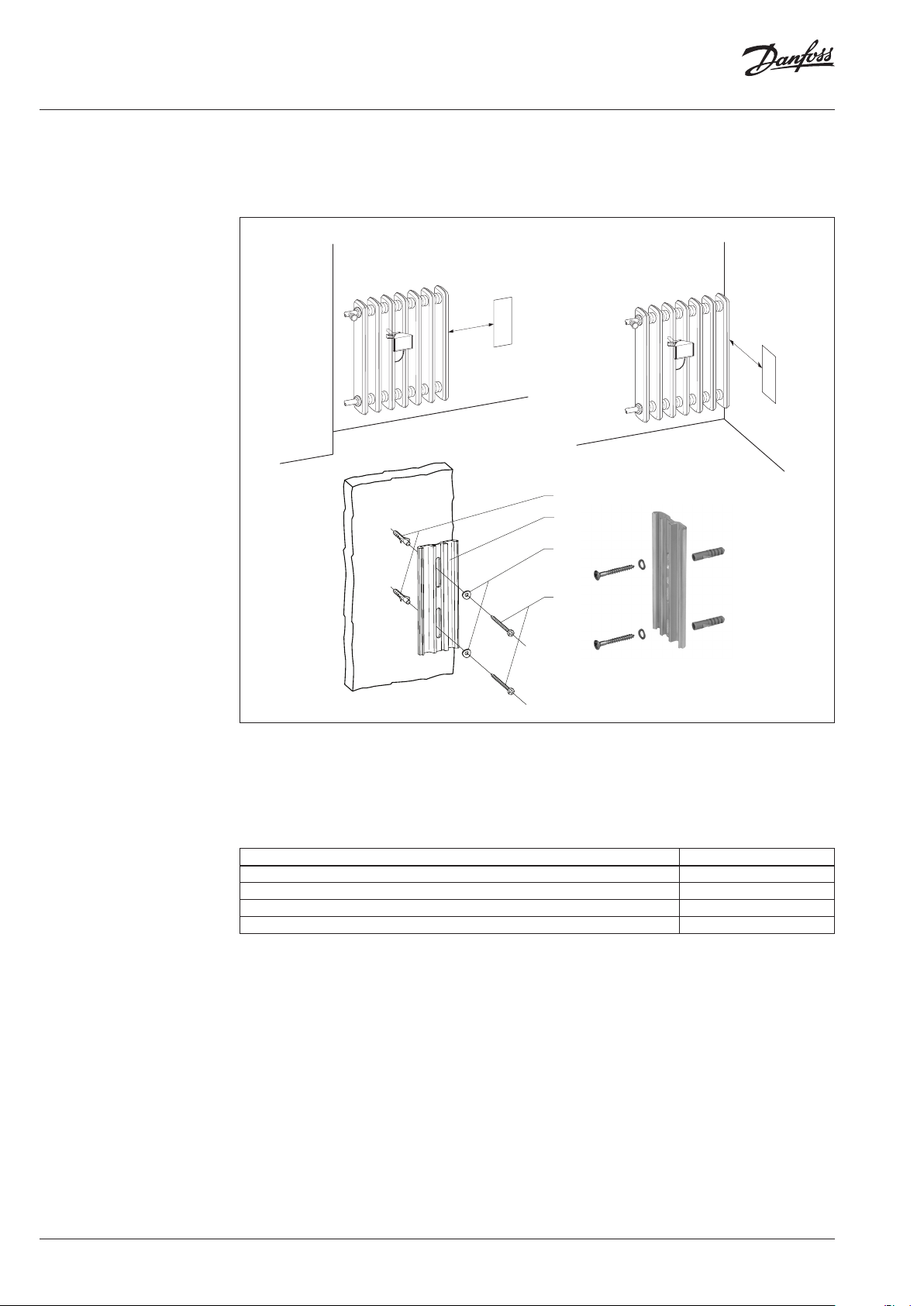
2. Wall Mounting
The heat cost allocator has to be wall-mounted if the overall height of the radiator is less than 250 mm
or if, for aesthetical reasons, the heat cost allocator cannot be mounted directly onto the radiator.
In this case, the heat cost allocator is wall-mounted on the side opposite to the valve and at a
minimum distance from the radiator of 10 cm.
at least
10 cm
088H2424
088H2345
088H2420
088H2423
at least
10 cm
• After marking and drilling the holes, the aluminium profile is fastened with 2 metal screws and
2 spring washer.
• The parts necessary for the wall-mounting are included in the corresponding fastening-parts
kits for the installation of the remote sensor.
• After installation of the device to the wall and the sensor to the radiator, the sensor cable is laid
in a cable duct.
• Mount the back plate through the 2 oval holes adjusted to the top edge of the 2 oval holes.
Mounting Accessories Code No.
2 plastic dowels Ø 5 mm 3.25 088H2424
1 aluminium back plate (supplied with SonoHCA) 088H2345
2 spring washers 088H2420
2 oval head wood screws 3 x 35 088H2423
4 | AQ353735633516en-010101 © Danfoss | 2020.09
Page 5
Operating Guide SonoHCA - Fastening parts and mounting accessories
3. Installation of Fastening
Parts Kits
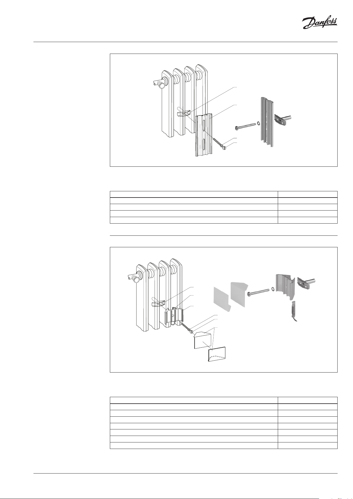
3.1 Installation to Sectional
Radiator, direct mounting
088H2408
088H2345
088H2420
088H2412
• For radiators made from cast iron it is necessary to apply heat transfer compound (Electrolube
HTS) onto the contact surfaces of the aluminium profile before installation. Mount the back
plate through the little hole in the middle.
Mounting Accessories Code No.
1 tensioning bracket 088H2408
1 aluminium back plate (supplied with SonoHCA) 088H2345
1 cylinder head screw M4 x 40 088H2412
1 spring washer B 4 088H2420
3.2 Sectional Radiator, wall
mounting
0088H2408
Remote
sensor
088H2410
088H2420
088H2412
088H2406
• The remote sensor has to be fixed in the receiver housing with adhesive to avoid loosen-ing.
• The contact surfaces of the cover angles have to be coated with adhesive before bringing them
together.
Mounting Accessories Code No.
1 tensioning bracket 088H2408
1 aluminium profile „receiver housing“ 088H2410
1 spring washer B 4, DIN 128 088H2420
1 cylinder head screw M4 x 40 (with crosshead) 088H2412
2 cover angles, white 088H2406
2 plastic dowels Ø 5 mm 3.25 (wall) 088H2424
2 oval head wood screws 3 x 35 (wall) 088H2423
AQ353735633516en-010101 | 5© Danfoss | 2020.09
Page 6

Operating Guide SonoHCA - Fastening parts and mounting accessories
3.3 Installation on Folded
Radiator
088H2413
088H2421
088H2345
088H2420
088H2411
• Mount the aluminium back plate through the small round hole
Mounting Accessories Code No.
1 hexagon nut B M4, DIN 934 088H2413
2 bracing angles 088H2421
2 spring washers B4, DIN 128 088H2420
1 oval head screw M4 x 30 088H2411
1 aluminium back plate (supplied with SonoHCA) 088H2345
3.4 Folded Radiator, wall
mounting
• If necessary use 2 x 2 bracing angles to improve more stability (photo) and, if needed, short the
screw
Mounting Accessories Code No.
2 hexagon nut B M4, DIN 934 088H2413
2 x 2 bracing angles 088H2421
4 spring washers B4, DIN 128 088H2420
2 oval head screw M4 x 30 088H2411
1 aluminium back plate (supplied with SonoHCA) 088H2345
088H2415
088H2414
088H2409
088H2405
088H2407
• The remote sensor has to be fixed in the receiver housing with adhesive to avoid loosening.
• The contact surfaces of the cover angles have to be coated with adhesive before bringing them
together.
Mounting Accessories Code No.
1 tensioning nut 088H2415
1 tensioning bolt 088H2414
1 aluminium profile «receiver housing» 088H2409
1 safety plate 088H2405
2 cover angles, white 088H2407
2 plastic dowels Ø 5 mm 3.25 (wall) 088H2424
2 oval head wood screws 3 x 35 (wall) 088H2423
6 | AQ353735633516en-010101 © Danfoss | 2020.09
Page 7

Operating Guide SonoHCA - Fastening parts and mounting accessories
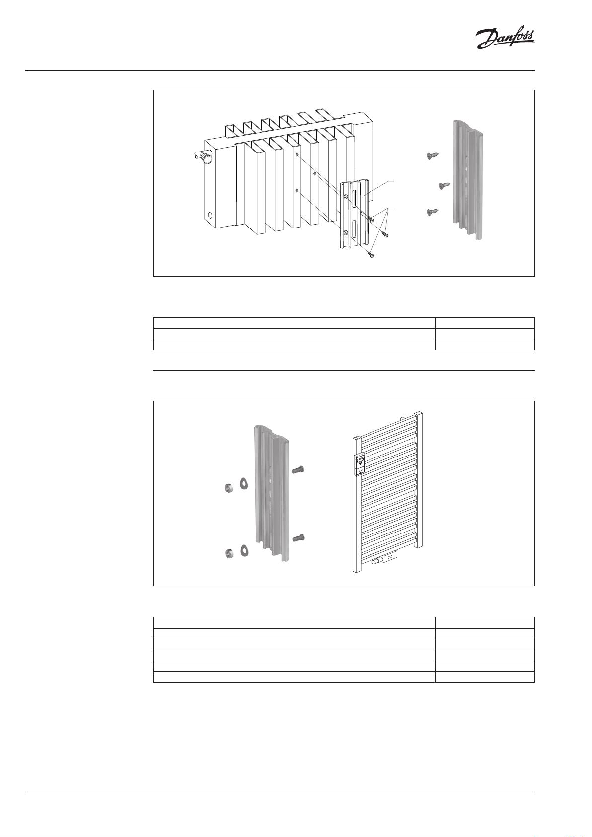
3.5 Installation to Panel
Type Radiator
• Mount the back plate through the 2 oval holes adjusted to the top edge of the 2 oval holes.
Mounting Accessories Code No.
2 threaded bolts M3 x 8 088H2422
2 spring washers B3, DIN 137 088H2418
2 slotted nuts M3, DIN 546 088H2416
1 aluminium back plate (supplied with SonoHCA) 088H2345
Tool: Screw driver size 5 for M3 -
or
Mounting Accessories Code No.
2 threaded bolts M3 x 8 088H2422
2 Nuts M3 6-kant size 5.5 with flange 1 aluminium back plate (supplied with SonoHCA) 088H2345
Tool: Socket wrench hexagonal size 5.5 -
or
Mounting Accessories Code No.
2 threaded bolts M3 x 8 088H2422
2 Nuts M3 mit 6 -kant size 5.5 1 aluminium back plate (supplied with SonoHCA) 088H2345
Tool: Socket wrench hexagonal size 5.5 -
or
Mounting Accessories Code No.
Silicone glue Pactan 6010,
(Vendor: Tremco Illbruck GmbH & Co. KG
D-92439 Bodenwöhr, T +49 (0) 9434 208 0)
1 aluminium back plate (supplied with SonoHCA) 088H2345
Tool: Acetone, Cotton wool -
088H2422
088H2345
088H2418
088H2416
088H2426
AQ353735633516en-010101 | 7© Danfoss | 2020.09
Page 8

Operating Guide SonoHCA - Fastening parts and mounting accessories
3.6 Mounting of heat cost
allocators with glue
Of using glue for t he mounting of heat cost allocat or, please refer to th e Standard EN834 .
Mounting Accessories Par t. No.
Silicone glue Pactan 6010,
(Vendor: Tremco Illbruck GmbH & Co. KG
D-92439 Bodenwöhr, T +49 (0) 9434 208 0)
1 aluminium back plate (supplied with SonoHCA) 555P005
Tool: Aceton, Cotton wool -
555P036
• Clean the aluminum back plate with Acetone soaked cotton wool
• Clean the gluing spot on the radiator with Acetone soaked cotton wool.
• Before and after the gluing, trash the first and last 10 cm of glue from the cartridge
• Assemble the heat cost allocator: Aluminum back plate to body and seal it.
• Apply 2 tracks of Pactan glue to the aluminum back plate, left and right of the channel
• Press the heat cost allocator to dedicated spot on the radiator and sway the heat cost allocator
to dispense the glue evenly.
• Press firmly and align. Wait 2-3 minutes check, align and press. Make sure the heat cost allocator
is mounted straight. The heat cost allocator must hold by itself. After 10 hours the heat cost
alloca-tor is firmly glued to radiator.
• Remove redundant glue with a screw driver. Clean the radiator with paper towels.
Removal of glued heat cost allocators
• Remove the aluminum back plate with a screw driver size 2 and a hammer: Position the screw
driver carefully in the middle channel and hammer until the aluminum plate can be removed.
• Remove glue carefully with a carpet cutter and clean glued surface with Acetone.
8 | AQ353735633516en-010101 © Danfoss | 2020.09
Page 9

Operating Guide SonoHCA - Fastening parts and mounting accessories
3.7 Panel Type Radiator, wall
mounting
088H2422
¼ BH**
or
½ BH**
20 mm
Remote
sensor
088H2417
088H2404
Remain inside sensor
Detached part
• The remote sensor has to be coated with heat transfer compound (Electrolube HTS) on the
contact surface.
• Turn on the pull-off nuts 088H2417 till it breaks. After put on the HK-sensor cover to ensure the
manipulation protection
088H2424
088H2345
088H2420
088H2423
• Mount the back plate through the 2 oval holes adjusted to the top edge of the 2 oval holes
Mounting Accessories Code No.
2 threaded bolts M3 x 8 088H2422
2 pull-off nuts M3 088H2417
1 HK-sensor cover 088H2404
2 plastic dowels Ø 5 mm 3.25 (wall) 088H2424
2 oval head wood screws 3 x 35 (wall) 088H2423
2 spring washers 088H2420
1 aluminium back plate (supplied with SonoHCA) 088H2345
AQ353735633516en-010101 | 9© Danfoss | 2020.09
Page 10
Operating Guide SonoHCA - Fastening parts and mounting accessories
3.8 Installation to PanelType Radiator with Front
Convection Plate
• The contact surfaces of the aluminium screws have to be coated with heat transfer compound
(Electrolube HTS).
• The aluminium screws have to be fastened with adhesive to avoid loosening
Mounting Accessories Code No.
3 sheet-metal screws 2.9 x 9.5 088H2419
1 aluminium back plate 088H2425
088H2425
088H2419
3.9 Bathroom radiator –
Towel rails
Heat cost allocator mounted verticaly on distributor or collector part
• Assembly with 2 threaded bolts welded on 75% BH +50mm on the side or front of the flow
distributor or return collector
Mounting Accessories Code No.
2 threaded bolts M3 x 8 088H2422
2 spring washers B3, DIN 137 088H2418
2 slotted nuts M3, DIN 546 088H2416
1 aluminium back plate (supplied with SonoHCA) 088H2345
Tool: Screw driver size 5 for M3 -
10 | AQ353735633516en-010101 © Danfoss | 2020.09
Page 11
Operating Guide SonoHCA - Fastening parts and mounting accessories
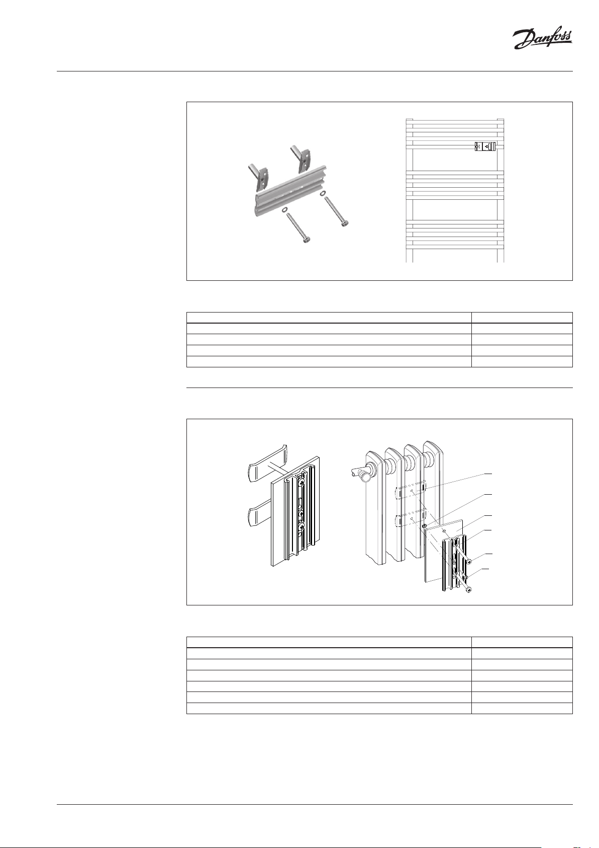
3.9 Bathroom radiator –
Towel rails (continuous)
Heat cost allocator mounted horizontally on cross tubes
• Assembly to the nearest possible place to the flow place or return place on the cross tubes on
75% BH with 2 tensioning brackets
Mounting Accessories Code No.
2 tensioning bracket 088H2408
1 aluminium back plate (supplied with EHCA) 088H2345
2 cylinder head screw M4 x 40 088H2412
2 spring washer B 4 088H2420
3.10 Sectional Radiator wide
Heat cost allocator mounted verticaly on distributor or collector part
088H2428
088H2430
088H2427
088H2345
088H2412
088H2429
• Assembly with 2 threaded bolts welded on 75% BH +50mm on the side or front of the flow
distributor or return collector
Mounting Accessories Code No.
2 tensioning bracket 50mm 088H2428
1 aluminium back plate (supplied with SonoHCA) 088H2345
1 heat conduc tor aluminium plate 60mm 088H2427
2 cylinder head screw M4 x 40 088H2412
1 cylinder head screw M3 x 10 088H2429
1 Nut M3 088H2430
AQ353735633516en-010101 | 11© Danfoss | 2020.09
Page 12
Operating Guide SonoCollect 112
SonoHCA - Fastening parts and mounting accessories
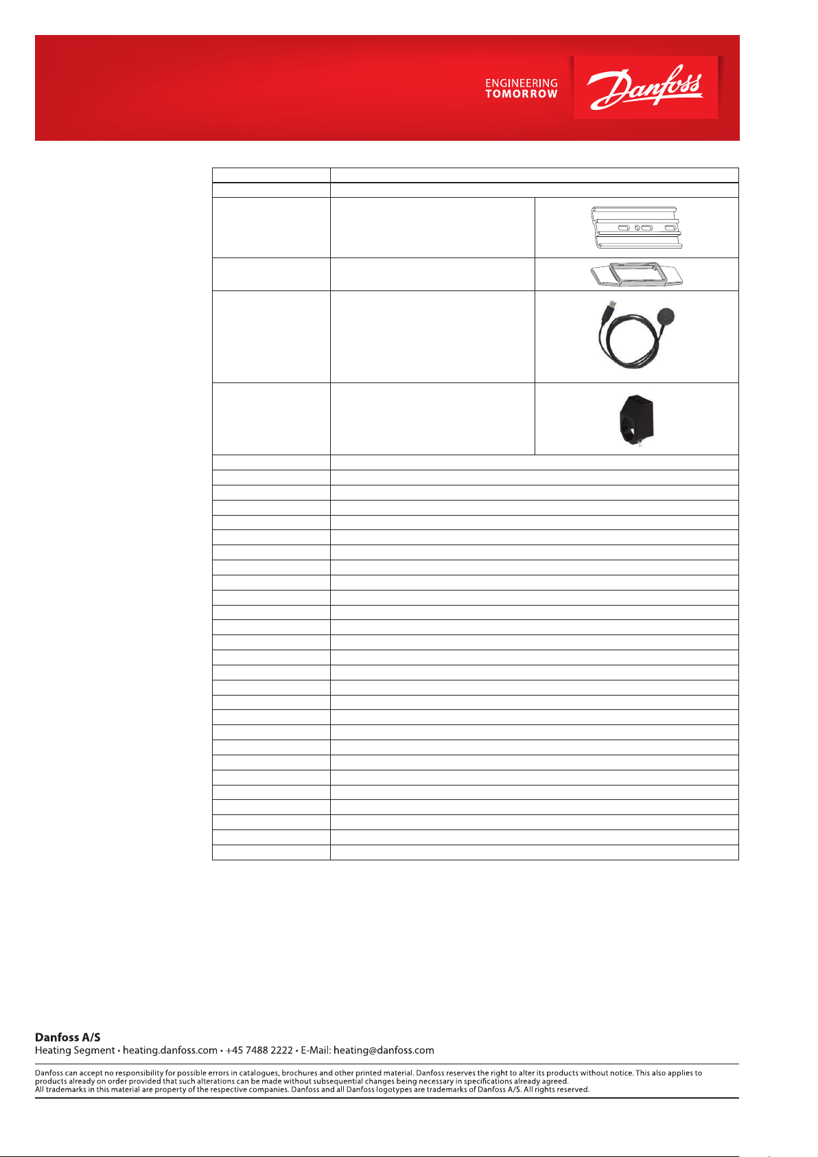
4. Overview mounting
accessories
Code No. Designation
088H2400 Replacement seal 1000 pieces
088H2345 Aluminium back plate
088H2401 Plastic cover
088H2402 Optical head USB
088H2403 Bracket for optical head
088H2404 Cover for sensor
088H2405 Safety plate
088H2406 Cover angles, white, Sectional radiator
088H2407 Cover angles, white, Folded radiator
088H2408 Tensioning bracket
088H2409 Aluminium plate case support for corrugated radiator
088H2410 Aluminium plate case support for sectional radiator
088H2411 Raised head screw M4 x 30
088H2412 Pan head screw 4 x 4 0
088H2413 Hexagon Nut B M4, DIN 934
088H2414 Tensioning bolt
088H2415 Tensioning nut
088H2416 Slotted nuts M3, DIN 546
088H2417 Pull-of f nuts M3
088H2418 Spring washers B3, DIN 137
088H2419 Tapping screw 2,9 x 9,5
088H2420 Spring washers
088H2421 Angle spreader
088H2422 Threaded bolts M3 x 8
088H2423 Oval head wood screws 3 x 35
088H2424 Plastic screw plug Ø 5 mm 3.25
088H2425 Aluminium back plate for front convection plate
088H2426 Glue Pactan 6010, 310 ml
088H2427 Heat conductor aluminium plate 60mm
088H2428 Tensioning bracket 50mm
088H2429 Cylinder screw M3 x 10
088H2430 Nut M3
© Danfoss | DHS-SMDBT/SI | 2020.0912 | AQ353735633516en-010101
 Loading...