

Page 1

SONO 3500 CT
Ultrasonic Flowmeter
Operating Instructions
Edition
11/2020
Classified as Business
Page 2

Classified as Business
Page 3

11/2020
Introduction
1
Safety notes
2
Description
3
Installing/Mounting
4
Electrical connection
5
Commissioning
6
Functions
7
Service and maintenance
8
Troubleshooting/FAQs
9
Technical data
10
Parameter lists
A
Settings
B
Ultrasonic Flowmeter SONO 3500 CT
Operating Instructions
AQ237286479555en-010402
Classified as Business
Page 4

Legal information
DANGER
indicates that death or severe personal injury will result if proper precautions are not taken.
WARNING
indicates that death or severe personal injury may result if proper precautions are not taken.
CAUTION
indicates that minor personal injury can result if proper precautions are not taken.
NOTICE
indicates that property damage can result if proper precautions are not taken.
WARNING
Danfoss products may only be used for the applications described in the catalog and in the relevant technical
ambient conditions must be complied with. The information in the relevant documentation must be observed.
Warning notice system
This manual contains notices you have to observe in order to ensure your personal safety, as well as to prevent
damage to property. The notices referring to your personal safety are highlighted in the manual by a safety alert
symbol, notices referring only to property damage have no safety alert symbol. These notices shown below are
graded according to the degree of danger.
If more than one degree of danger is present, the warning notice representing the highest degree of danger will
be used. A notice warning of injury to persons with a safety alert symbol may also include a warning relating to
property damage.
Qualified Personnel
The product/system described in this documentation may be operated only by personnel qualified for the specific
task in accordance with the relevant documentation, in particular its warning notices and safety instructions.
Qualified personnel are those who, based on their training and experience, are capable of identifying risks and
avoiding potential hazards when working with these products/systems.
Proper use of Danfoss products
Trademarks
Note the following:
documentation. If products and components from other manufacturers are used, these must be recommended
or approved by Danfoss. Proper transport, storage, installation, assembly, commissioning, operation and
maintenance are required to ensure that the products operate safely and without any problems. The permissible
All names identified by ® are registered trademarks of Danfoss A/S. The remaining trademarks in this publication
may be trademarks whose use by third parties for their own purposes could violate the rights of the owner.
Disclaimer of Liability
We have reviewed the contents of this publication to ensure consistency with the hardware and software
described. Since variance cannot be precluded entirely, we cannot guarantee full consistency. However, the
information in this publication is reviewed regularly and any necessary corrections are included in subsequent
editions.
Local Importer name and address
For goods delivered to UK, importer name and address is:
Danfoss Ltd.
Oxford Road
UB9 4LH Denham
UK
SONO 3500 CT
Operating Instructions, 11/2020, AQ237286479555en-010402
Page 5

5
SONO 3500
Legal information
Table of contents
1
Introduction ............................................................................................................................................. 9
1.1
1.2
1.3
1.4
1.5
2
Safety notes .......................................................................................................................................... 14
2.1
2.2
2.3
2.4
2.5
3
Description ............................................................................................................................................ 17
3.1
3.2
3.3
3.4
3.5
Items supplied ........................................................................................................................... 9
Checking the consignment ..................................................................................................... 10
Device identification ................................................................................................................ 10
Further Information ................................................................................................................. 12
Transportation and storage ..................................................................................................... 13
General safety instructions ..................................................................................................... 14
Manufacturer's design and safety statement ......................................................................... 14
Conformity with European directives ..................................................................................... 15
Lithium batteries...................................................................................................................... 15
Installation in hazardous area ................................................................................................. 16
Overview ................................................................................................................................. 17
System components ............................................................................................................... 17
Design ..................................................................................................................................... 17
Features .................................................................................................................................. 18
Principle of operation .............................................................................................................. 19
4
5
Operating Instructions, 11/2020, AQ237286479555en-010402
Installing/Mounting ................................................................................................................................ 21
4.1
4.2
4.2.1
4.2.2
4.2.3
4.3
4.3.1
Flowmeter installation ............................................................................................................. 21
Sensor installation .................................................................................................................. 21
Inlet/Outlet conditions ............................................................................................................. 21
Reduction ................................................................................................................................ 25
Insulation ................................................................................................................................. 26
Transmitter installation (compact/remote versions) ................................................................ 26
Installation wall mounting kit (remote transmitter) .................................................................. 27
Electrical connection ............................................................................................................................. 28
5.1
5.2
Backup battery ........................................................................................................................ 28
Connecting battery (battery-powered versions and mains-powered versions with back-up
battery) .................................................................................................................................... 28
5.3
5.4
5.4.1
5.4.2
Connecting sensor link cable .................................................................................................. 29
Connecting power supply cable (main-powered systems only) ............................................. 30
Connecting pulse output signal cable(s) ................................................................................. 31
Finishing connection ............................................................................................................... 32
CT
Classified as Business
Page 6

Legal information
SONO 3500 CT
010402
6
5.4.2.1 Connecting battery (battery-powered versions and mains-powered versions with back-up
battery) ................................................................................................................................. 33
5.5
Compact and remote transmitters: Connecting output and power supply ............................. 33
5.6
5.6.1
5.6.2
5.6.3
5.7
5.8
5.8.1
5.8.2
6
Commissioning ...................................................................................................................................... 39
6.1
6.2
6.3
6.4
6.5
6.5.1
6.5.2
6.5.3
6.5.4
6.5.5
6.5.6
6.5.7
6.5.8
7
Functions ............................................................................................................................................... 50
Optional current output module .............................................................................................. 35
Finishing connection ............................................................................................................... 36
Connecting .............................................................................................................................. 37
Finishing connection ............................................................................................................... 37
Wiring energy calculator type INFOCAL 9 ............................................................................. 38
Sealing of SONO 3500 CT .................................................................................................... 38
User sealing ............................................................................................................................ 38
Verification sealing .................................................................................................................. 38
Introduction ............................................................................................................................. 39
Operating the local display ..................................................................................................... 39
Navigating the menu structure ................................................................................................ 40
Start-up routine ....................................................................................................................... 41
Commissioning via PDM......................................................................................................... 42
Installing and connecting the IrDA interface adapter .............................................................. 43
Installing EDD files .................................................................................................................. 43
Adding the device to the network ........................................................................................... 44
Configuring the device ............................................................................................................ 44
Optimizing the system ............................................................................................................ 46
Output A, terminals 56/57: ...................................................................................................... 47
Output B, terminals 66/67: ...................................................................................................... 48
Checking the operation readiness .......................................................................................... 48
7.1
7.2
7.3
7.4
8
Service and maintenance ....................................................................................................................... 53
8.1
8.2
8.3
8.4
8.5
8.6
8.7
8.8
Unit selection .......................................................................................................................... 50
Number of decimal digits ........................................................................................................ 50
Password-protected data ........................................................................................................ 51
Hardware key .......................................................................................................................... 51
Maintenance ........................................................................................................................... 53
Battery replacement ................................................................................................................ 53
Service menu .......................................................................................................................... 56
Technical support ................................................................................................................... 57
Application-specific data - Qualification certificate ................................................................. 57
Qualification certificate............................................................................................................ 59
Return procedures .................................................................................................................. 61
Battery disposal ...................................................................................................................... 62
Operating Instructions, 11/2020, AQ237286479555en-
Classified as Business
Page 7

7
SONO 3500
Legal information
9
Troubleshooting/FAQs ........................................................................................................................... 63
9.1
9.2
10 Technical data ....................................................................................................................................... 68
10.1 SONO 3500 CT ...................................................................................................................... 68
10.2
10.3
10.4
10.5
A
Parameter lists ...................................................................................................................................... 73
A.1
A.2
A.3
A.4
A.5
A.6
B
Settings ................................................................................................................................................ 85
B.1
Error codes ............................................................................................................................. 63
Diagnosing with PDM ............................................................................................................. 64
Battery .................................................................................................................................... 69
Sensor for SONO 3500 CT ..................................................................................................... 70
Dimensional drawings for SONO 3500 CT ............................................................................. 71
Pipe dimensions for SONO 3500 CT ...................................................................................... 71
Identification ............................................................................................................................... 73
Output ......................................................................................................................................... 74
Diagnostic ................................................................................................................................... 76
Meter setup ................................................................................................................................ 81
Human Interface ......................................................................................................................... 83
Unit conversion table .................................................................................................................. 83
Factory settings .......................................................................................................................... 85
B.2
Factory settings for Modbus communication ............................................................................. 86
Operating Instructions, 11/2020, AQ237286479555en-010402
CT
Classified as Business
Page 8

Legal information
SONO 3500 CT
010402
8
Classified as Business
Operating Instructions, 11/2020, AQ237286479555en-
Page 9

SONO 3500 CT
Operating Instructions, 11/2020,
9
Introduction
1.1 Items supplied
Compact system
1
These instructions contain all information required to commission and use the device. It is
your responsibility to read the instructions carefully prior to installation and commissioning. In
order to use the device correctly, first review its principle of operation.
The instructions are aimed at persons mechanically installing the device, connecting it
electronically, configuring the parameters and commissioning it, as well as service and
maintenance engineers.
The device can be delivered as either a compact or a remote system.
• Sensor
• Transmitter
• Connection PCB
• DVD with documentation and cerificates
• Safety note
• Calibration report
• Sensor link cable
• Connection accessories
AQ237286479555en-010402
Classified as Business
Page 10

10
CT
010402
Remote system
• Sensor
• Transmitter
• Connection PCB
• DVD with documentation and cerificates
• Safety note
• Calibration report
• Mounting kit with bracket and terminal box
• Sensor link cable
• Connection accessories
Note
Scope of delivery may vary, depending on version and add-ons. Make sure the scope of
delivery and the information on the nameplate correspond to your order and the delivery
note.
1.2 Checking the consignment
1.
Check the packaging and the device for visible damage caused by inappropriate handling
during shipping.
2.
Report any claims for damages immediately to the shipping company.
3.
Retain damaged parts for clarification.
4.
Check the scope of delivery by comparing your order to the shipping documents for
correctness and completeness.
1.3 Device identification
The SONO 3500 CT flowmeter is delivered with different labels (nameplates) on the
transmitter and sensor. The transmitter and sensor are matched paired.
The transmitter has two nameplates. One (silver) is placed on the front of the transmitter.
The transmitter system nameplate (white) is placed on the right side of the transmitter. Both
provide valuable information about the device and system. The sensor system nameplate
(white) is placed on middle of the sensor.
Note Identification
Identify your device by comparing your ordering data with the information on the product and
specification nameplates.
Operating Instructions, 11/2020, AQ237286479555en-
Classified as Business
SONO 3500
Page 11

SONO
Operating Instructions, 11/2020,
11
①
System number (order code identifying selected options and system serial number)
②
Transmitter production code and serial number
③
Sensor production code and serial number
④
Maximum flow value (qs), Nominal flow value (qp), Minimum flow value (qi)
⑤
Pulse value (output A)
⑥
Pulse width (output A)
⑦
⑧
⑨
⑩
⑪
⑫
⑬
Transmitter system nameplate
Cable length (one transducer cable); Software version
Calibration factor; Production year
Ambient temperature range
Type approval number
Accuracy class
Environmental class
Verification markings
Figure 1-1 Transmitter system nameplate
3500 CT
AQ237286479555en-010402
Page 12

CT
010402
12
①
②
③
④
⑤
⑥
⑦
⑧
Water temperature range
⑨
Production year
⑩
System number (order code identifying selected options and system serial number)
⑪
⑫
Accuracy class
⑬
Environmental class
⑭
Verification markings
⑮
PED marking
Sensor system nameplate
Sensor production code and serial number
Dimension (nominal size ordered)
Pressure rating (nominal pressure rate ordered)
Maximum flow value (qs), Nominal flow value (qp), Minimum flow value (qi)
Cable length (one transducer cable)
Calibration factor
Ambient temperature range
Type approval number
Figure 1-2 Sensor system nameplate
Note
The matched paired transmitter and sensor shall be mounted together
Please check that the system nameplates of transmitter and sensor have the same system
serial number.
1.4
Product information on the Internet
Further Information
The Operating Instructions are available on the Danfoss homepage, where further
information on the range of Danfoss flowmeters may also be found: Product information
(https://www.danfoss.com/en/products/energy-metering/dhs/energy-metering/)
SONO 3500
Operating Instructions, 11/2020, AQ237286479555en-
Page 13

SONO 3500
13
NOTICE
● Provide additional packaging as necessary.
1.5
1.3.1 Keep the original packaging for subsequent transportation.
1.3.2 Devices/replacement parts should be returned in their original packaging.
1.3.3 If the original packaging is no longer available, ensure that all shipments are properly
Transportation and storage
To guarantee sufficient protection during transport and storage, observe the following:
packaged to provide sufficient protection during transport. Danfoss cannot assume liability
for any costs associated with transportation damages.
Insufficient protection during storage
The packaging only provides limited protection against moisture and
infiltration.
Operating Instructions, 11/2020, AQ237286479555en-010402
CT
Page 14

CT
010402
14
Safety notes
2
CAUTION
Correct, reliable operation of the product requires proper transport, storage, positioning and
assembly as well as careful operation and maintenance.
Note
Alterations to the product, including opening or improper modifications of the product are not
permitted.
If this requirement is not observed, the CE mark and the manufacturer's warranty will expire.
2.1 General safety instructions
Only qualified personnel should install or operate this instrument.
2.2 Manufacturer's design and safety statement
● Responsibility for the choice of flowmeter pipe material as regards abrasion and corrosion
resistance lies with the purchaser. The effect of any change in process medium during
operation of the meter should be taken into account. Incorrect selection of flowmeter pipe
material could lead to failure of the flowmeter.
● Stresses and loading caused by earthquakes, traffic, high winds and fire damage are not
taken into account during flowmeter design.
● Do not install the flowmeter such that it acts as a focus for pipeline stresses. External
loading is not taken into account during flowmeter design.
● Please be aware of the risk of installing the sensor in a highly vibrating environment.
Parts may shake loose and the complete system must be monitored in that case.
● Flanges and joints as well as related pressure/temperature (p/t) classification has been
described in EN 1092-1. See ferrite steel group 1E1: table 15.
● During operation do not exceed the pressure and/or temperature ratings indicated on the
data label or in these operating instructions.
● It is recommended that all installations include an appropriate safety valve and adequate
means for draining.
● Under the „Pressure Equipment Directive" (PED), this product is a pressure accessory
and not approved for use as a safety accessory, as defined by the PED.
Environmental conditions according MID (Directive 2014/32/EU)
● Environment class: E2 (electromagnetic), M1 (mechanical)
● Climatic class: -10°C - +55°C, condensing, closed
Operating Instructions, 11/2020, AQ237286479555en-
SONO 3500
Page 15

15
WARNING
Potential hazard
–
Do not expose contents to water.
2.3 Conformity with European directives
The CE marking on the device symbolizes the conformity with the following European directives:
Electromagnetic compatibility EMC 2014/30/EU
Directive of the European Parliament and of the Council on the harmonization of the laws of the
Member States relating to electromagnetic compatibility
Low voltage directive LVD 2014/35/EU
Directive of the European Parliament and of the Council on the harmonization of the laws of the
Member States relating to the making available on the market of electrical equipment designed
for use within certain voltage limits
Pressure equipment directive PED EMC 2014/68/EU
Directive of the European Parliament and of the Council on the harmonization of the laws of the
Member States relating to electromagnetic compatibility
Radio equipment directive RED 2014/53/EU
Directive of the European Parliament and of the Council on the harmonization of the laws of the
Member States relating to the making available on the market of radio equipment and repealing
Directive 1999/5/EC
2.4 Lithium batteries
Measuring instruments directive MID 2014/32/EU
Directive of the European Parliament and the Council on the harmonization of the laws of the
Member States relating to the making available on the market of measuring instruments
Restriction of Hazardous Substances RoHS 2011/65/EU
Directive of the European Parliament and the Council on the restriction of the use of certain
hazardous substances in electrical and electronic equipment
The applicable directives can be found in the EU declaration of conformity of the specific device.
Lithium batteries are primary power sources with high energy content designed to represent
the highest possible degree of safety.
Lithium batteries may present a potential hazard if they are abused electrically or
mechanically.
• Observe the following precautions when handling and using lithium batteries:
–
Do not short-circuit, recharge or connect with false polarity.
–
Do not expose to temperature beyond the specified temperature range or incinerate
the battery.
–
Do not crush, puncture or open cells or disassemble battery packs.
–
Do not weld or solder to the battery’s body.
SONO 3500 CT
Operating Instructions, 11/2020, AQ237286479555en-010402
Page 16

CT
010402
16
WARNING
NOT allowed for use in hazardous areas!
2.5 Installation in hazardous area
Equipment used in hazardous areas must be Ex-approved and marked accordingly!
This device is NOT approved for use in hazardous areas!
SONO 3500
Operating Instructions, 11/2020, AQ237286479555en-
Page 17

17
Description
3
Sensor type
Transmitter
Flowmeter system
DN 100 to DN 1200
SONO 3500 CT transmitter
3.1 Overview
The SONO 3500 CT ultrasonic flowmeter systems consist of a sensor and a transmitter. The
transmitter is type-approved with the custody transfer (CT) approval for use in energy
metering systems. The transmitter is designed to measure flow water applications.
The ultrasonic flowmeter transmitter comes as a mains-powered version with battery backup.
The following table shows the ultrasonic flowmeter systems with these transmitter types:
SONO 3500 CT (2-path)
3.2 System components
The flowmeter system includes:
●
Mains-powered transmitter with battery backup
●
The sensor is a 2-path sensor with flanges and inline transducers wet-calibrated from
factory together with the transmitter (DN 100 (4") to DN 1200 (48"))
3.3 Design
The transmitter is designed with fiberglass reinforced polyamide enclosure for remote or
compact installation in normal areas. The remote versions are available with up to 30 meter
distance from flowmeter to transmitter. When ordered as a compact version in the series
SONO 3500 CT the transducer cables are pre-mounted at the sensor.
incl SONO 3500 CT
SONO 3500 CT
Operating Instructions, 11/2020, AQ237286479555en-010402
SONO 3500 CT display
The transmitter is available in an IP67/NEMA 4X/6 enclosure.
For spare part cases the transmitter is always ordered as part of a complete flowmeter
system.
The transmitter can be ordered preprogrammed with the given sensor data (system serial
number).
Page 18

CT
010402
18
3.4 Features
The following features are available:
●
Mains-powered transmitter
●
Battery backup with 3.6 V Lithium single D-cell battery
●
Suitable for sensor pipe diameters from DN 100 (4") up to DN 1200 (48")
●
IP67 (NEMA 4X/6) rated polyamide transmitter enclosure
●
Factory preset to the nominal dimensions of pipe type and pipe size
●
Programming via SIMATIC PDM
●
Local control panel with single push button, 8-digit display and IrDA optical interface for
communication with SIMATIC PDM
●
Display showing accumulated volume as well as instantaneous flow rate. The displayed
units are m
●
Two digital outputs for volume pulse or alarm
3
/h and m
3
●
4-20mA output (optional)
Applications
The main application for the type-approved SONO 3500 CT flowmeters is measurement of
water flow in district heating plants, local networks, boiler stations, substations, chiller plants,
irrigations plants, and other general water applications.
Integration
The flowmeter pulse output is often used as input for an energy meter or as input for digital
systems for remote reading. The transmitter has two pulse outputs, with functions that can
be individually selected, and integrated IRDA (optical eye) communication interface (Modbus
RTU).
The settings of the transmitter, for example flow and pulse output rate, are defined when
ordering the complete flowmeter. If the flowmeter forms part of an energy meter system for
custody transfer, no further approvals are needed, except possible local approvals.
Transmitter communication solutions
The transmitter supports Modbus RTU communication via the optical IrDA interface at the
display, enabling the change of different transmitter settings using the SIMATIC PDM
software tool.
The transmitter is configured in a combination of hardware (HW) and firmware (FW). For the
communication and parametrization via SIMATIC PDM a firmware-specific device
description (EDD) is needed.
Operating Instructions, 11/2020, AQ237286479555en-
SONO 3500
Page 19

19
3.5 Principle of operation
Physical principle
Figure 3-1 Velocity distribution along sound path
A sound wave travelling in the same direction as the liquid flow arrives at point B from point
A in a shorter time than the sound wave travelling against the flow direction (from point B to
A).
SONO 3500 CT flowmeters
The difference in sound transit time indicates the flow velocity in the pipe.
Since delay time is measured at short intervals both in and against flow direction,
temperature has no influence on measurement accuracy.
In SONO 3500 CT flowmeters the ultrasonic transducers are placed at an angle θ in relation
to the pipe axis. The transducers function as transmitters and receivers of the ultrasonic
signals. Measurement is performed by determining the time the ultrasonic signal takes to
travel with and against the flow. The principle can be expressed as follows:
v = K × (t
B,A
A,B
) / (t
A,B
× t
B,A
) = K × Δt/t²
– t
where
v = Average flow velocity
t = Transit time
K = Proportional flow factor
This measuring principle offers the advantage that it is independent of variations in the actual
sound velocity of the liquid, i.e. independent of the temperature.
The mechanical/geometrical pipe data is transducer angle (θ), distance between sensors (L)
and pipe dimension (D
and Du) shown in the figure below.
i
SONO 3500 CT
Operating Instructions, 11/2020, AQ237286479555en-010402
Page 20

CT
010402
20
Figure 3-2 Measuring principle
The ultrasonic signal is sent directly between the transducers. The advantage gained
sending signals from point to point is an extremely good signal strength.
Operating Instructions, 11/2020, AQ237286479555en-
SONO 3500
Page 21

21
Installing/Mounting
4
CAUTION
Direct sunlight
4.1 Flowmeter installation
The flowmeter installation is done in two steps:
1.
Sensor installation
2.
Transmitter installation
Environment
SONO 3500 CT flowmeters are suitable for indoor and outdoor installations.
●
Make sure that temperature and ambient specifications indicated on the device type
plate/label are not exceeded.
Device damage.
The device can overheat or materials become brittle due to UV exposure.
Protect the device from direct sunlight.
Make sure that the maximum permissible ambient temperature is not exceeded.
Refer to the information in Technical data (Page 68).
Ambient temperature for transmitter:
●
-10 °C to +55 °C (14 to 131 °F)
●
Non-MID versions -10 to +60°C (14 to 140°F)
●
The enclosure rating of the transmitter is IP67 (NEMA 4X/6) or better.
4.2 Sensor installation
4.2.1
SONO 3500 CT
Operating Instructions, 11/2020, AQ237286479555en-010402
Inlet/Outlet conditions
Requirement for straight inlet before flowmeter
In order to maximize performance it is necessary to have straight inlet and outlet flow
conditions before and after the flowmeter.
Furthermore, a minimum distance between flowmeter and pumps and valves must be
respected.
It is also important to centre the flowmeter in relation to flanges and gaskets.
Page 22

CT
010402
22
Make sure that flowmeter is positioned as low as possible to prevent air from being trapped
in flowmeter at transducers.
Find a position on the pipeline where inlet pipe to flowmeter has a straight length as
specified below.
Single bend
1 x 90° bend
L2: Min. 10 x pipe diameter
L1: 3 x pipe diameter
Operating Instructions, 11/2020, AQ237286479555en-
SONO 3500
Page 23

23
Dual bend
2 x 90° bends in the same plane
L2: Min. 10 x pipe diameter
L1: 3 x pipe diameter
Triple bend
3 x 90° bends in two planes
L2: Min. 20 x pipe diameter
L1: 3 x pipe diameter
SONO 3500 CT
Operating Instructions, 11/2020, AQ237286479555en-010402
Page 24

CT
010402
24
Valves and pumps
Orienting the sensor
Valves
L2: Min. 10 x pipe diameter, fully open valve
L1: 3 x pipe diameter
Pumps:
L2: Min. 20 x pipe diameter
L1: 3 x pipe diameter
Horizontal orientation, terminal box upwards or downwards
Precautions
In horizontal installation avoid any upward/downward position of the transducers.
Avoid installation at the highest point in the system because air bubbles will be trapped in
flowmeter.
Avoid installation at a point where there is a free outlet after flowmeter.
Operating Instructions, 11/2020, AQ237286479555en-
SONO 3500
Page 25

25
Note
To obtain maximum battery lifetime with the Lithium Thionyl Chloride battery pack. it is
Flowmeter pipe section may be installed in either a horizontal or vertical position.
recommended to install the flowmeter transmitter in an upright position.
4.2.2
Reduction
SONO 3500 CT
Operating Instructions, 11/2020, AQ237286479555en-010402
Page 26

CT
010402
26
4.2.3
Installation in large pipes
The flowmeter can be installed between two reducers as shown. At 8° reducing angles the
below pressure drop curve applies.
Delta-P example:
A water flow velocity of 3 m/s (V) in a sensor with a diameter reduction from DN 200 to DN
100 (D
= 0.5) gives a pressure drop of 9 mbar.
1/D2
L2: Min. 10 x pipe diameter
Insulation
Both versions can be insulated.
We always recommend insulation of sensor in the compact or remote version. For compact
versions the insulation can prevent heat transfer to transmitter.
4.3 Transmitter installation (compact/remote versions)
The transmitter is packed separately - ready for plug-in into base part.
There are two mounting versions of the transmitter (as shown in figures below):
●
remote transmitter
●
compact transmitter
Remote transmitter Compact transmitter
Note
The matched paired transmitter and sensor shall be mounted together. At installation, please
check that the system nameplates of transmitter and sensor have the same system serial
number.
Operating Instructions, 11/2020, AQ237286479555en-
SONO 3500
Page 27

27
4.3.1 Installation wall mounting kit (remote transmitter)
Mount wall/pipe mounting bracket in an appropriate place.
Wall mounting
Pipe mounting
Note
Take coaxial cable length into consideration and allow adequate space for cable inlets
underneath and on both sides.
SONO 3500 CT
Operating Instructions, 11/2020, AQ237286479555en-010402
Page 28

010402
28
Electrical connection
5
WARNING
Skills
WARNING
Danger of electric shock!
The transmitter is mains-powered with battery backup
Important:
On compact versions, all transducer cables are pre-mounted from factory.
Mounting of output pulse cables is identical for compact and remote versions.
Only qualified personnel may carry out work on the electrical connections.
Never install the device with the mains voltage switched on!
5.1 Backup battery
The mains-powered transmitter is supplied with a single backup lithium battery.
In the event of power failure battery will take over power supply of unit.
The battery is not of a rechargeable type and must be replaced latest after 6 years.
Note
Male battery plug is not connected to plug female socket connection upon delivery. This
connection must be made to enable backup battery power supply.
5.2 Connecting battery (battery-powered versions and mains-powered
versions with back-up battery)
Plug in male battery plug. Ensure that the wire is inserted into the small channel leading
from plug to battery.
SONO 3500 CT
Operating Instructions, 11/2020, AQ237286479555en-
Page 29
29
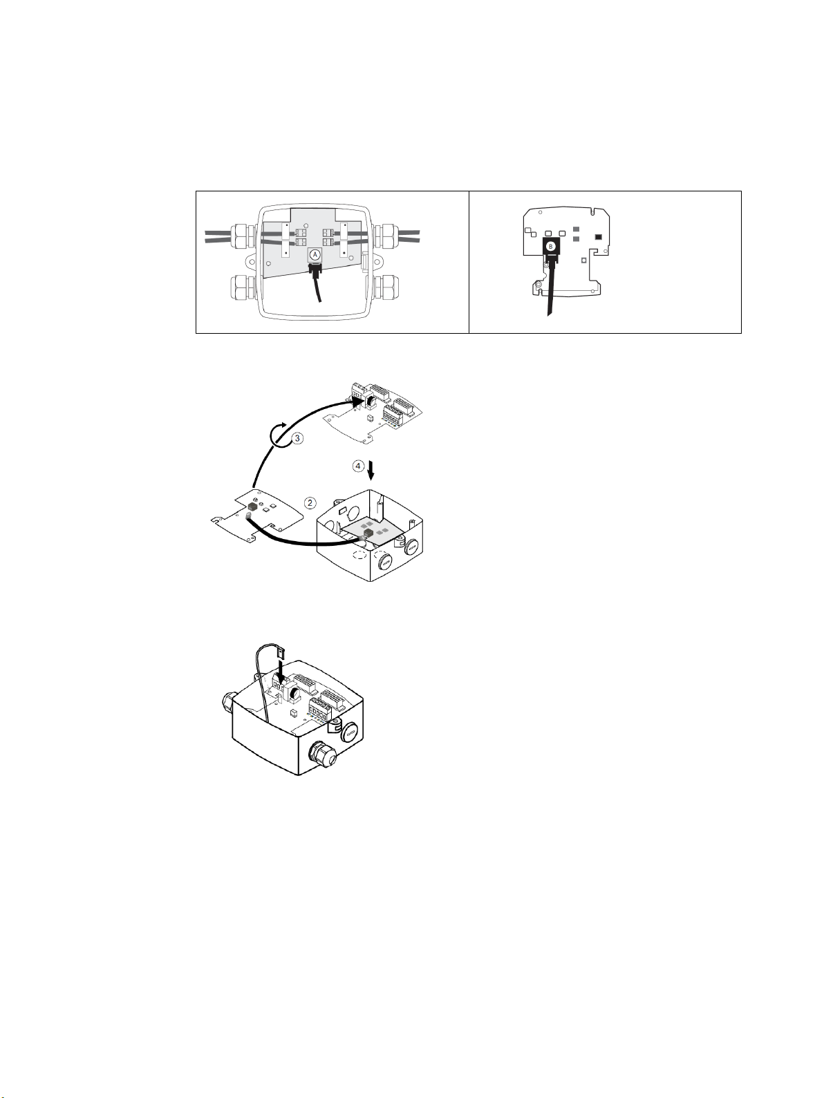
5.3 Connecting sensor link cable
1. Remove the plastic lid from the terminal box.
2. Click the sensor link cable onto sensor connection board (A) and onto transmitter
connection board (B).
3. Turn the transmitter connection board so that the connection cable is facing
downwards.
4. Click the transmitter connection board into the terminal box.
5. Connect protective earth wire.
SONO 3500 CT
Operating Instructions, 11/2020, AQ237286479555en-010402
Page 30

010402
30
WARNING
Power supply requirements
WARNING
Wire insulation
National Installation Code
the flowmeters are installed is met.
Note
Conductor terminal
The wire size for the output
.
5.4 Connecting power supply cable (main-powered systems only)
Make sure the power supply requirements stated on the nameplates are met!
The insulation between the connected mains supply and the low voltage supply for the
flowmeter must be rated with at least double or reinforced insulation at mains voltage.
For field wiring installation: Ensure that the
of the country in which
terminals are AWG24 to AWG16 or 0.205 mm2 to 1.500 mm²
1. Replace blind plug with cable gland.
2. Push power supply cable through open gland.
3. Connect power supply to L1, N and protective earth (PE) and tighten cable strap (C).
5.
Tighten cable gland for power supply cable (approx. 20 Nm).
SONO 3500 CT
Operating Instructions, 11/2020, AQ237286479555en-
Page 31
31
CAUTION
Pulse output
isolation.
Note
Cables with voltage
Keep the output signal cable(s) separated from cables with voltages > 60 V.
Note
Ingress protection
To guarantee the IP67 (NEMA 4X/6) degree of protection, use
specifications.
Note
Protected terminal
Keep the output signal cable(s) separated from cables with voltages > 60 V.
5.4.1 Connecting pulse output signal cable(s)
If no output signals are needed, proceed with "Finishing connection".
The pulse output must be connected to equipment complying with Low-Voltage Directive in
order to be considered safe. The isolation within FUS080 pulse output is only a functional
1. Replace blind plug with cable gland (if two output signals are required, use a double
entry cable gland).
2. Push output cable(s) through open gland.
3. Connect output cable(s).
SONO 3500 CT
Operating Instructions, 11/2020, AQ237286479555en-010402
4. Tighten cable gland for output cable(s) (approx. 20 Nm).
cables with the required
Page 32

010402
32
Note
EMC performance
Incorrect fixing of the output cable shield will affect the EMC performance.
Note
Optional current output module
If you want to install the optional current output module, proceed with chapter Installing
and connecting optional current output module (Page 35) before mounting the transmitter.
Note
Grounding
To ensure identical potential for sensor and transmitter, a direct grounding of transmitter
and sensor is recommended.
Note
Aligning the gasket
Please ensure that the gasket between terminal box and transmitter is well
tightening the screw (Min. torque 0.5 Nm).
5.4.2 Finishing connection
Mount the transmitter.
aligned before
Operating Instructions, 11/2020, AQ237286479555en-
SONO 3500 CT
Page 33

33
WARNING
Power supply requirements
5.4.2.1 Connecting battery (battery-powered versions and mains-powered versions with
back-up battery)
Plug in male battery plug. Ensure that the wire is inserted into the small channel leading from
plug to battery.
5.5 Compact and remote transmitters: Connecting output and power supply
The wiring of output and power supply is done in three steps:
1.
Wiring power supply
2.
Wiring pulse output (if relevant)
3.
Mounting transmitter
Step 1: Wiring power supply
Make sure the power supply requirements stated on the nameplates are met!
SONO 3500 CT
Operating Instructions, 11/2020, AQ237286479555en-010402
Page 34

CT
010402
34
Note
Cable straps
It is recommended to use cable straps.
Note
Sensor grounding
To ensure identical potential for sensor and transmitter, a direct grounding of transmitter and
sensor is recommended.
CAUTION
Pulse output
functional isolation.
1.
Connect power supply to L1, N and protective earth (PE).
Figure 5-2 Output and power supply connection
2.
Fix the power supply cable to the terminal housing with the clamp.
3.
Ground transmitter and sensor.
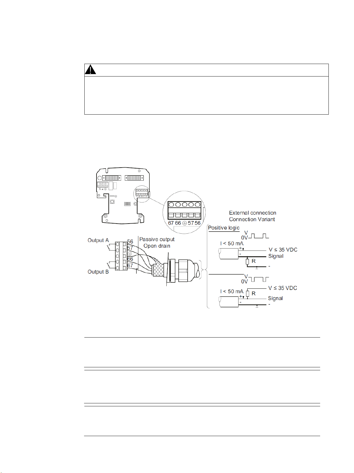
Step 2: Wiring pulse output
The pulse output must be connected to equipment complying with Low Voltage Directive in
order to be considered safe. The isolation within the transmitter pulse output is only a
1.
Prepare the cable ends as shown in the figure above.
2.
Connect output cables to terminals 56 and 57 (Output A) and to 66 and 67 (Output B)
according to use.
The output functions are used as shown in the figure above.
3.
Ground the cable shielding by fixing it with the clamp.
Operating Instructions, 11/2020, AQ237286479555en-
SONO 3500
Page 35

connection
5.4 Wiring energy calculator type INFOCAL 9
Operating Instructions, 11/2020,
35
Note
Current output range during start up
bled (default setting) the output is 3.6 mA during start
up. When the current output module is disabled the output is fixed to 4 mA.
Note
Restricted use of the optional current output module
signal is not approved for custody transfer use.
Electrical
CAUTION
EMC performance
Incorrect fixing of the cable shield will affect the EMC performance!
Step 3: Mounting Transmitter
1.
Tighten the power supply and pulse output cable glands.
2.
Mount the transmitter.
Figure 5-3 Mounting transmitter on terminal box
5.6 Optional current output module
The optional current output module converts the flow signal into a 4-20 mA output signal. The
4 mA always equals 0 flow rate and the 20 mA equals the Qp value selected via the order code.
The default Qp can be found on the transmitter nameplate.
The current output module is passive and therefore needs an external power supply.
When the current output module is ena
The module can be used with all mains-powered SONO3500 CT versions, but the output
SONO 3500 CT
Page 36

CT
Operating Instructions, 11/2020, AQ237286479555en-010402
36
WARNING
Danger of electric shock!
CAUTION
EMC performance
affect the EMC performance!
Note
Power supply
power supply.
Note
Current output module
(Page 85).
CAUTION
Protective earth
5.6.1 Finishing connection
Never install the device with the mains voltage switched on!
Current output cable shield must be connected. Incorrect fixing of the cable shield may
Installing
The current output module is a passive module and should only be used with external
To support the function with current output module the default communication settings for
the transmitter is recommended. See Factory settings for Modbus communication
1.
Remove transmitter/terminal box lid.
2.
Carefully mount current output module on the eight pins.
3.
Fasten module to transmitter connection board by use of a M3x5 screw (0.5 Nm).
The M3x5 screw also functions as earth conductor (EMC).
See also
Optional current output module (Page 35)
SONO 3500
Page 37

37
Note
Grounding
and sensor is recommended.
Note
Aligning the gasket
tightening the screw (Min. torque 0.5 Nm).
5.6.2 Connecting
The output terminals are marked 31 and 32 with corresponding polarity + and - on the
terminal strip. The connector is for shielding.
The requirements for the current output cable, for example max. load can be found in
AUTOHOTSPOT.
1. Replace blind plug with cable gland (if two output signals are required, use a double entry
cable gland).
2. Push output cable through open gland.
3. Connect output cable to terminals 31, 32 and .
4.
Tighten cable gland for current output cable (approx. 20 Nm).
5.6.3 Finishing connection
Mount the transmitter.
To ensure identical potential for sensor and transmitter, a direct grounding of transmitter
Please ensure that the gasket between terminal box and transmitter is well aligned before
SONO 3500 CT
Operating Instructions, 11/2020, AQ237286479555en-010402
Page 38

CT
Operating Instructions, 11/2020, AQ237286479555en-010402
38
SONO 3500 CT in supply pipe
Infocal 9 terminal
57 (ground)
11 (q1-)
56 (flow pulse)
52 (q2+)
Transmitter
Sensor
Remote version
Under transmitter display frame
On bottom of transmitter
On sensor body
On side of transmitter
5.7 Wiring energy calculator type INFOCAL 9
Energy calculator is typically connected via the pulse output A of the transmitter.
Wiring to flow meter SONO 3500 CT:
56 (flow pulse) 10 (q1+)
SONO 3500 CT in return pipe Infocal 9 terminal
57 (ground) 11 (q2-)
5.8 Sealing of SONO 3500 CT
5.8.1 User sealing
After finishing the installation and electrical connection, it is recommended to seal the
flowmeter as shown. Drill through marked drilling holes in terminal box and
transmitter/lid. Seal the transmitter on both sides with either one or two wires.
5.8.2 Verification sealing
This illustration shows how the device is verification sealed.
Note
For type-approved and verified SONO3500 CT flowmeters
The HW key is located behind the display and is thereby protected by the display sealing.
The verification sealing may only be broken with the acceptance of the local authorities.
SONO 3500
Page 39

39
Commissioning
6
Symbol
Description
6.1 Introduction
Commissioning the device includes the following steps:
1.
2.
3.
It is recommended to read the basic guide to the local display and the menu structure in
Operating the local display (Page 39) and Navigating the menu structure (Page 40) before
commissioning the device.
Resetting the battery lifetime (see Start-up routine (Page 41)).
Checking values in the service menu.
Configuring the device via SIMATIC PDM (see Commissioning via PDM (Page 42)).
6.2 Operating the local display
The local display is divided into 3 areas:
1.
Top area with symbols for status information
2.
Mid area with actual readings
3.
Lower area with index number of the shown menu
Activate the push button to go the next index menu and related information.
Figure 6-1 Operating the local display
Table 6-1 Status information symbols
SONO 3500 CT
Operating Instructions, 11/2020, AQ237286479555en-010402
Mains power supply connected
Battery charge status
Warning
Service menu
Page 40

CT
010402
40
Symbol
Description
Menu
Parameter
Display example
Comments
Battery status
There are two symbols for battery charge status:
4.
"Battery full" indicates battery charge above the warning level (6-year hour counter).
5.
"Battery low" indicates battery charge below the warning level and that the battery should
be replaced.
Note
"Battery low" only indicates that battery charge is below a pre-set level, not that charge is
zero.
Flow measurement continues uninterrupted until the battery is completely drained.
Table 6- 2 Battery status information symbols
6.3 Navigating the menu structure
Use the push button to navigate between the following menu items:
Table 6- 3 Menu items
Menu 1 Flow volume totalizer 1
Menu 2 Flow volume totalizer 2
Battery status, full
Battery status, low
Factory preset is forward
volume flow.
The battery symbol shows
full.
Factory preset for reverse
flow.
Negative values indicate
reverse flow calculation.
Menu 3 Actual flow rate
Menu 4 Alarm codes
Menu 5 Display test
Negative values indicate
reverse flow calculation.
Each code refers to a specific alarm.
Check of all segments. Display toggles between all
segments on/off.
SONO 3500
Operating Instructions, 11/2020, AQ237286479555en-
Page 41

41
Menu
Parameter
Display example
Comments
Service menu (Page 56).
Table 6-4 Service menu
Service menu
6.4 Start-up routine
1.
Power-up device.
2.
Reset battery status indicator as described below.
Resetting the battery counter
Note
The reset can also be carried out via SIMATIC PDM.
When a new battery is installed and the plug is connected, the transmitter start-up
routine begins. The display shows the active software version, e.g. 2.04.
The service menu is
accessible from all menus by
pressing push button for
minimum 2 seconds. For
more information on the
complete service menu, see
After ten seconds the message "reset.bat" will appear.
1.
Press push button within six seconds to reset the internal battery counter. The message
"accept" will appear.
2.
Press push button again within six seconds in order to reset the internal battery counter.
The battery indicator now shows full. If the push button is not pressed again, the battery
indicator will show "Low".
Figure 6-2 Reset internal battery counter
* Firmware version, here version 2.03
SONO 3500 CT
Operating Instructions, 11/2020, AQ237286479555en-010402
Page 42

CT
42
Note
For instructions on installation and operation of SIMATIC PDM, refer to the SIMATIC PDM
Getting Started (included in the documentation package that comes with PDM).
Note
PDM version
Note
Default password
Any data change in PDM requires a password. The default password is 1000. For further
information, see Password-protected data (Page 51).
Note
For type-approved and verified SONO 3500 CT flowmeter the settings are HW key protected
and
verification
sealing. The
local authorities.
6.5 Commissioning via PDM
SIMATIC PDM (Process Device Manager) is a software package for configuring,
parameterizing, commissioning, and maintaining field devices (for example transducers).
Among other features, SIMATIC PDM contains a simple process for monitoring process
values, interrupts and status/diagnosis signals of a field device.
required is SIMATIC PDM V6.1
can only be read, but not changed via PDM. This HW key is protected via the
verification sealing can only be broken by the user with the acceptance of the
In the following it is described how the device is commissioned using SIMATC PDM.
The commissioning is divided into the following steps:
1.
Installing and connecting the IrDA interface adapter (Page 43)
2.
Installing EDD files (Page 43)
3.
Adding the device to the network (Page 44)
4.
Configuring the device (Page 44)
5.
Optimizing the system (Page 46)
6.
Checking the operation readiness (Page 48)
Operating Instructions, 11/2020, AQ237286479555en-010402
SONO 3500
Page 43

SONO 3500 CT
Operating Instructions, 11/2020,
43
6.5.1 Installing and connecting the IrDA interface adapter
Note
IrDA driver installation
For installation of the IrDA driver, refer to the instructions delivered with the adapter.
1.
Connect IrDA adapter to PC
2.
Mount adapter on the transmitter
When the IrDA adapter is connected correctly, a small icon appears on the taskbar of your
PC. When the mouse is placed on this icon, the device information will be shown (e.g.
"SN1033 is in range").
6.5.2 Installing EDD files
Install the PDM device driver as follows:
1. Download update from the Internet on http://www.danfoss.com. (www.danfoss.com
Check that the EDD (electronic device descriptions) is the version valid for the device.
2. Open "Manage Device Catalog" from Start → SIMATIC → SIMATIC PDM.
3. Navigate to PDM device driver, select device and click "OK". The driver is installed on
the PC.
)
AQ237286479555en-010402
Page 44

CT
010402
44
6.5.3 Adding the device to the network
It is recommended to configure the project in PDM before setting the parameters.
Add device to SIMATIC Modbus network:
1. Select [File → New]
Type in a project name, e.g. SONO 3500 CT
2. Right click on your new project, select [Insert New Object → Networks].
3. Right click on your Networks, select [Insert New Object → Communication Network].
4. Click on [Assign Device Type] and select Networks → MODBUS → MODBUS networks
→ MODBUS network.
5. Click [OK] and click [OK] again.
6. Right click on MODBUS network and select [Insert New Object → Object]
7. Click on [Assign Device Type] and assign the MODBUS device to SITRANS
FUS/E080 [Devices → MODBUS → Sensors → Flow → Ultrasonic → SIEMENS AG →
SITRANS FUS/ E080] and click [OK].
Name device according to application requirements (max. 32 characters) and click [OK].
Set up communication parameters for SIMATIC MODBUS network.
8. Select Networks → MODBUS network.
9. Right click on Modbus network and select Object Properties.
10. On the Communication tab, select MODBUS communication to activate IrDA.
6.5.4 Configuring the device
In the following it is described how to configure the device by defining all sensor specific
parameters.
Note
Measurement accuracy
A correct flowmeter installation is required to ensure optimum measurement accuracy.
SONO 3500
Operating Instructions, 11/2020, AQ237286479555en-
Page 45

45
Read all parameters
Read, write device data
Before any parameterization is done it is necessary to read all parameters from the device
into the offline table of SIMATIC PDM. The offline table merely contains default data.
1. Open PDM device driver.
2. Select "Upload to PC/PG .." Select "Execute even if the device TAG does not match the
project data TAG.", and click "OK" to read all parameters to the offline table.
After closing the dialog box, all loaded parameters should show "Loaded" in the status of
the PDM table. For a complete parameter list, see Parameter lists (Page 73).
3. Store factory set default values on your local PC ("File" → "Export") in order to be able to
retrieve default settings.
Note Status field
• "Changed" indicates off-line data not yet stored in the device.
Only parameters (data) shown with white background can be changed.
• "Loaded" indicates actual device data.
To view possible settings, right-click and select "Help".
SONO 3500 CT
Operating Instructions, 11/2020, AQ237286479555en-010402
Page 46

CT
010402
46
SONO 3500 CT
Preset: Alarm
Pulse width
Preset: 5 ms
6.5.5 Optimizing the system
After storage of the settings, the parameters can be set according to use.
The following shows how to set Pulse Output A and Qmax. For other parameters, refer to
"Parameter list" in the appendix.
Setting Pulse Output and Maximum Flow (Q
1. In SIMATIC PDM navigate to menu "Device" → "Pulse guide"
The "guide" calculates the pulse-frequency at the max flow condition and tells you how
close you are on over-speeding the pulse-output.
The volume per pulse is freely scalable from 0.000001 to 10000 units per pulse. It also
calculates the minimum volume per pulse you can choose to avoid pulse over-speeding.
The maximum output frequency depends on the pulse selected; e.g. maximum output
frequency at 5 ms is 100 Hz. Increasing the pulse width lowers the maximum output
frequency.
2. Select maximum flow rate (never to be exceeded).
3. Select an appropriate pulse width, e.g. 5 ms.
4. Enter a value in "Amount per pulse A", e.g. 100, to define the volume/pulse with respect
to the "Minimum amount per pulse value".
5. Press "Apply Change of Pulse" to apply the settings.
6. If needed, proceed with setting Pulse Output B according to application specific
requirements (Default setting = Alarm).
Output A and B setting
For SONO 3500 CT, output A and B settings depend on the ordering: Recommended
settings, see the following table. The SONO 3500 CT settings cannot be changed according
approval requirements, and are therefore read only.
) via SIMATIC PDM
max
Output A
Output B
Pulse value A & B
(depending on DN value)
Forward or reverse pulses
Preset: Forward
Forward or reverse pulses, alarm, call-up
Preset: See scheme for SONO 3500 CT or the
following settings for INFOCAL 9 energy calculator.
Note
For type-approved and verified SONO 3500 CT flowmeter the settings are HW key protected
and therefore read only. This HW key is protected via the verification sealing. The verification
sealing can only be broken by the user with the acceptance of the local authorities.
SONO 3500
Operating Instructions, 11/2020, AQ237286479555en-
Page 47

47
DN
Pulse setting (liter/pulse)
100
2.5
125
2.5
150
2.5
250
10
350
10
500
50
600
100
700
100
800
100
1000
100
6.5.6 Output A, terminals 56/57:
Pulse rate can be seen on transmitter side label (system nameplate).
The settings are depending on the ordering. The following table shows the recommended
pulse output settings (pulse width 5 ms), which can be adapted to heat calculator INFOCAL 9.
200 10
300 10
400 50
900 100
1200 100
Note
For use with a energy calculator the pulse value must correspond to pulse setting of energy
calculator.
SONO 3500 CT
Operating Instructions, 11/2020, AQ237286479555en-010402
Page 48
CT
010402
48
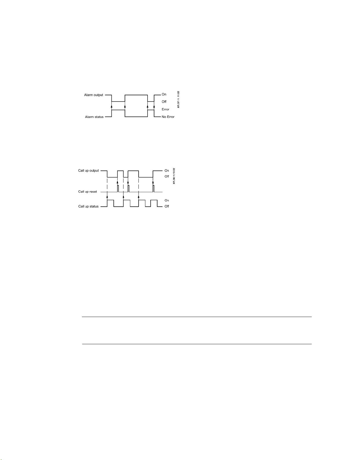
6.5.7 Output B, terminals 66/67:
The output B setting must be selected according to application specific requirements (Default
setting = Alarm).
Preset to alarm indication:
Example: If track 1 is not measuring, a "triangle" alert appears on display. Failure code "F1"
appears in display menu 4, and relay output terminals switch to "off".
Call up indication:
When output B is configured as "call-up", the output is activated by an alarm condition and
remains on until it is manually reset via communication interface and the PDM program (or
via manually power down of the device).
A new alarm will not activate a "call-up" function if the "call-up" function is still active from a
previous alarm.
6.5.8 Checking the operation readiness
All parameters are now set and defined according to the application.
1. Select: "Device" → "Download to device..." to download the parameters to the device.
Note
Before downloading the parameters, check that all listed data are loaded or changed and
in accordance with the application requirements.
2. Select "Execute even if the device TAG does not match the project data TAG." and click
"OK" to download all changes from the table to the device.
Operating Instructions, 11/2020, AQ237286479555en-
SONO 3500
Page 49

49
View process values
The system is now ready for normal operation.
1.
Select "View" → "Display" to see all measured process values.
2.
Verify that the fields show the expected values.
Store settings on the PC
Note
Measured Track Values
The "Measured Track Values" should show stable values within the normal range, i.e. the
gains should be stable values between 3 and 12 (smaller sizes low values and larger sizes
high values) and the actual velocities for the paths should be stable, constant and smoothly
changing values between 0 and 10 m/s.
Store the device settings after verifying the values.
●
Choose: "Read" → "Upload to PC" to get all the settings.
●
Store the complete settings on your PC via "File" → "Export".
SONO 3500 CT
Operating Instructions, 11/2020, AQ237286479555en-010402
Page 50

CT
010402
50
Functions
7
7.1 Unit selection
The device is delivered with totalizer and flow rate units in m and m3/h, respectively, as
standard. However, it is possible to manually configure the device to operate with other units.
Changing the units
Go via PDM menu "Device" → "Unit guide". Select the new unit from the list and click on
"Apply Change of Units". The change should be stored into the transmitter via "Device" →
"Download to Device" afterwards
.
7.2 Number of decimal digits
Figure 7-1 Unit selection
Note
The display is only able to show m3 and m3/h
If the units are changed to units other than m3 and m3/h, the display will not show any unit
indication after the measured value on the display. To show the new customer unit on the
display, a sticker can be used to show units. This sticker should be affixed to the transmitter
display.
For the display values (totalizers in menu 1 and 2 and flow in menu 3) "Auto adjust decimal
point" is the default setting. This means that the number of digits after the decimal point
automatically will be reduced with increasing number of digits before the decimal point.
SONO 3500
Operating Instructions, 11/2020, AQ237286479555en-
Page 51

51
7.3 Password-protected data
In the MODBUS communication via SIMATIC PDM, the flowmeter information is protected
by a password. The default password is "1000" and it can be changed after gaining access
to the flowmeter or via the PDM menu "Device" → "Change Password". The password can be
changed without the use of the HW key.
Figure 7-2 Change password
Click "Write new password to the device" and "Close"
7.4 Hardware key
To gain access to protected parameters of the transmitter, a hard-ware jumper (HW key)
must be installed as shown below. The HW key place is located internally on the right top
part of PCB behind the display as shown.
Note
For type-approved and verified SONO 3500 CT flowmeter the HW key is protected by a
verification sealing on the display frame (see Sealing of SONO 3500 CT (Page 38)). The
verification sealing can only be broken by the user with the acceptance of local authorities.
SONO 3500 CT
Operating Instructions, 11/2020, AQ237286479555en-010402
Page 52

CT
010402
52
Figure 7-3 HW key behind the display (placed on the right pins)
Note
Important
In this mode, with the HW key installed, many parameters in PDM are opened. If these
parameters are changed, it can seriously affect the meter accuracy and operation. Be careful
when writing new parameters.
Changing the HW-protected parameters
1.
Disconnect power supply to transmitter, i.e. battery plug and the mains power supply
2.
Remove frame and display from transmitter.
3.
Insert HW key vertically on right pins as shown in figure above.
4.
Remount display and frame on transmitter.
5.
Restart device.
6.
Make parameter changes via PDM.
7.
Download parameter changes to device.
8.
Remove HW key by following the steps above.
Operating Instructions, 11/2020, AQ237286479555en-
SONO 3500
Page 53

53
Service and maintenance
8
NOTICE
Repair and service
Note
The flow sensors are defined as non-repairable products.
NOTICE
Battery replacement interval
8.1 Maintenance
The device is maintenance-free. However, a periodic inspection according to pertinent
directives and regulations must be carried out.
An inspection can include check of:
●
Ambient conditions
●
Seal integrity of the process connections, cable entries, and cover screws
●
Reliability of power supply, lightning protection, and grounds
Repair and service must be carried out by Danfoss authorized personnel only.
8.2 Battery replacement
It is recommended to replace the battery pack at the latest after 6 years.
SONO 3500 CT
Operating Instructions, 11/2020, AQ237286479555en-010402
Page 54

CT
010402
54
Battery lifetime
The battery lifetime depends on the frequency of mains supply failure. Under normal
temperature and working conditions a battery can have an operation lifetime up to 6 years.
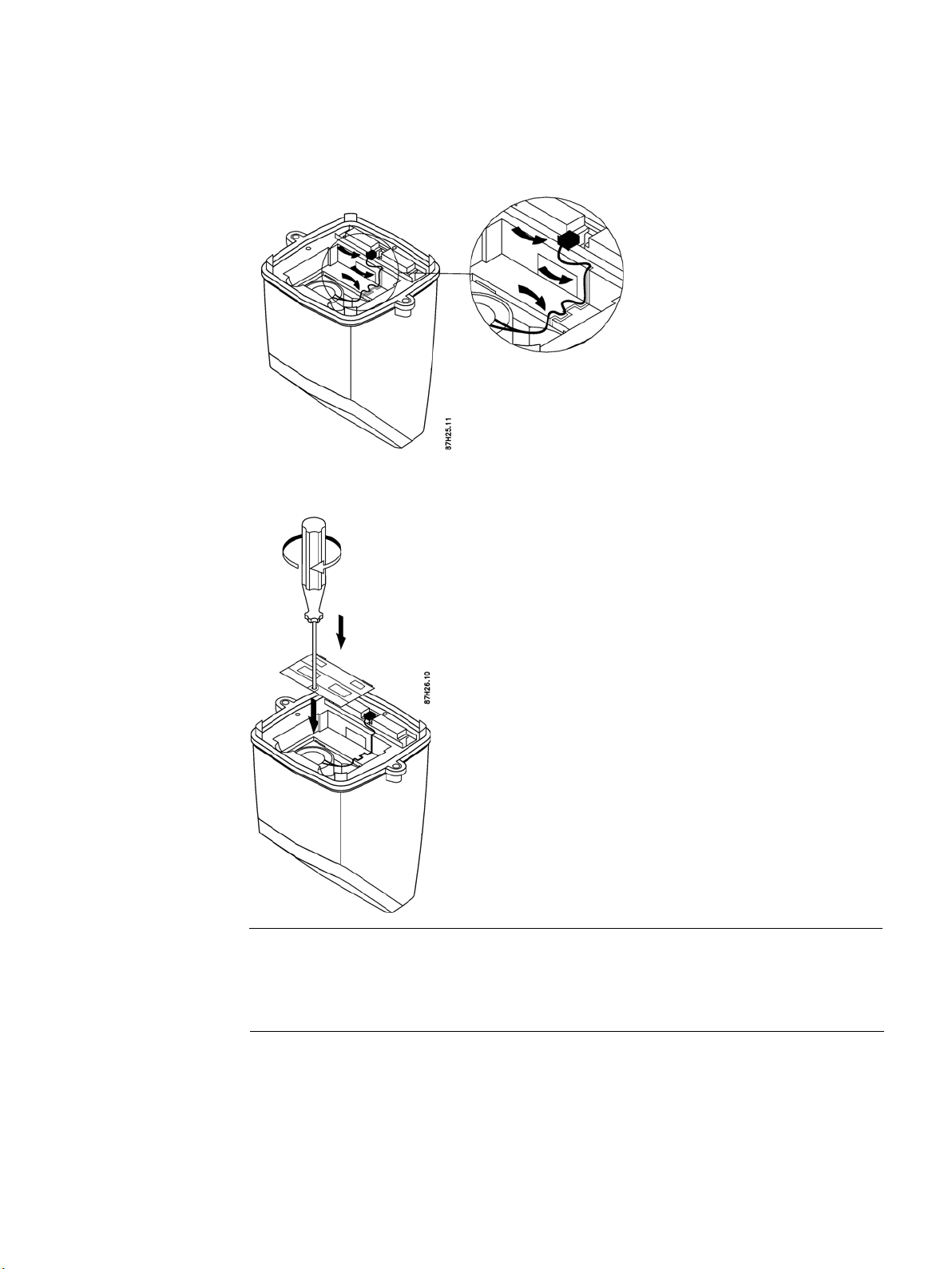
1.
Unscrew battery cover and remove old battery pack.
2.
Fit new battery pack in transmitter.
Operating Instructions, 11/2020, AQ237286479555en-
SONO 3500
Page 55
SONO 3500 CT
Operating Instructions, 11/2020,
55
3.
Connect battery.
Ensure that wire is inserted into small channel leading from plug to battery.
4.
Remount battery cover.
Note
Every time a battery is fitted and connected, the unit runs a start-up routine.
A battery replacement does not influence the transmitter settings and accumulated
process values.
AQ237286479555en-010402
Page 56

CT
010402
56
Menu
Parameter
Display example
Comments
Sensor distance (Page 66).
Resetting the internal battery counter
After replacing the batteries, reset the internal battery counter in order to indicate the power
capacity correctly.
Note
Battery capacity
The transmitter setting for the battery capacity is pre-configured by the ordered version. To
ensure the correct battery status calculation the replacement battery shall be the same type
and have the specific capacity. The capacity setting can be controlled via SIMATIC PDM.
8.3 Service menu
The service menu ( ) is accessible from all menus by pressing the push button for minimum
2 seconds. To return back to the main menu you need to press the push button for a minimum
of 2 seconds again. If no action is taken you will be taken back to the main menu after 10 min
if back-up battery powered or after 2 min if mains-powered.
Table 8-1 Service menu
1 Gain path 1 and path 2
2 Signal level AB and BA of path 1
3 Signal level AB and BA of path 2
4 Transition time (μs) AB of path 1
5 Transition time (μs) AB of path 2
Gain for path 1 and path 2 ranging
from 0 to 15. The optimal gain values
are explained in Figure 9-2 SI‐ TRANS
FUS080 Gain step vs.
Signal level for Downstream and
Upstream Sensor for path 1 typically
between 230 and 380
Signal level for Downstream and
Upstream Sensor for path 2 typically
between 230 and 380
Time of Flight Downstream, from Sensor A
to B for path 1
Time of Flight Downstream, from Sensor
A to B for path 2
6 Transition time (μs) BA of path 1
Time of Flight Upstream ,from Sen‐ sor B
to A for path 1
SONO 3500
Operating Instructions, 11/2020, AQ237286479555en-
Page 57

SONO 3500 CT
Operating Instructions, 11/2020,
57
Menu
Parameter
Display example
Comments
7 Transition time (μs) BA of path 2
8 Delta time (ns) of path 1
9 Delta time (ns) of path 2
10 Velocity (m/s) path 1
11 Velocity (m/s) path 2
Time of Flight Upstream from Sensor B
to A for path 2
Delta Time Of Flight for path 1,
difference between Down and upstream TOF
Positive value equals positive flow
Delta Time Of Flight for path 2,
difference between Down and upstream TOF
Positive value equals positive flow
Measured flow velocity for path 1
Measured flow velocity for path 2
See also
Optional current output module (Page 35)
8.4 Technical support
Additional Support
Contact your local Danfoss representative and offices if you have additional questions about
the device.
Find your local contact partner at: www.danfoss.com (www.danfoss.com
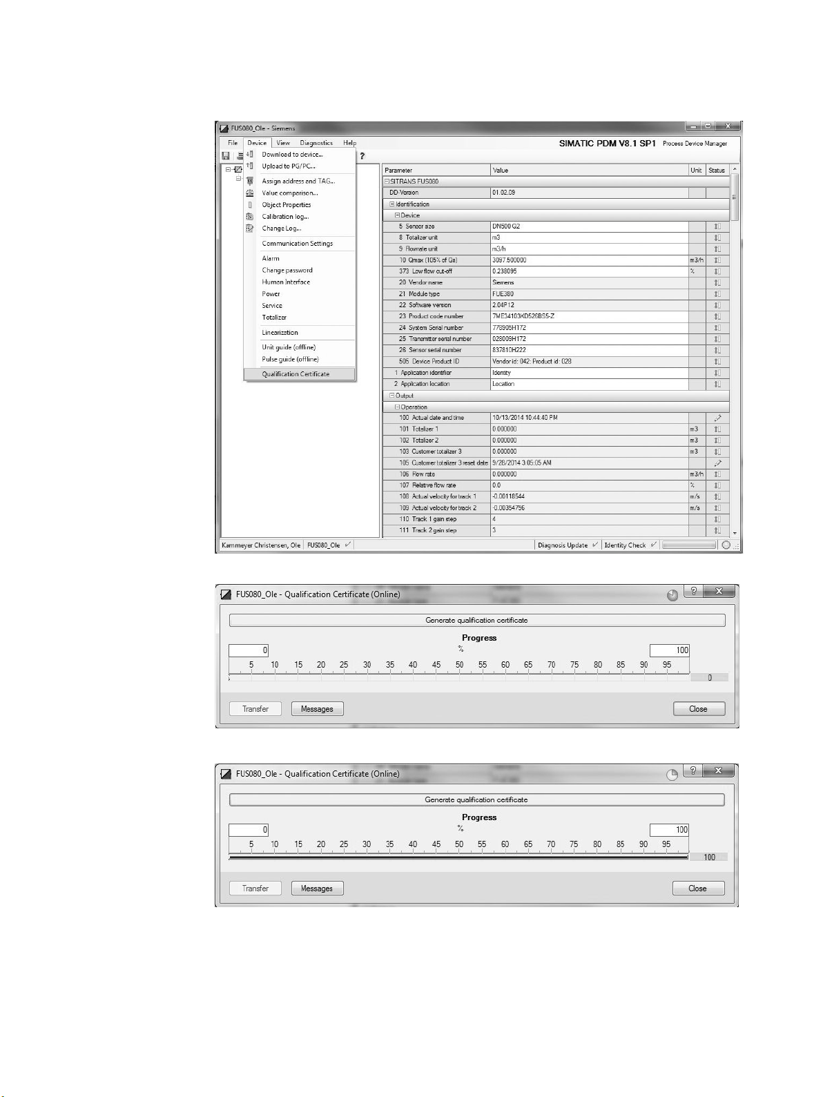
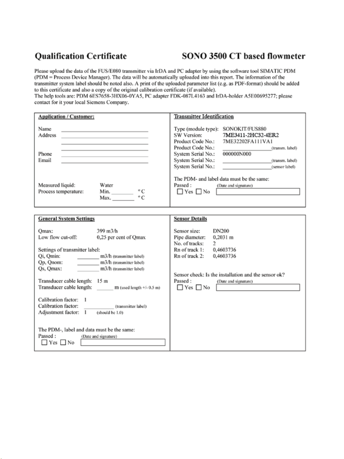
8.5 Application-specific data - Qualification certificate
In case the device needs service, the technical support team will typically request
information about the application and the flowmeter.
)
●
Prepare a sketch of the installation/application.
●
For your convenience you may create a qualification certificate via SIMATIC PDM
AQ237286479555en-010402
Page 58
CT
010402
58
1.
In PDM click on "Device" → "Qualification Certificate".
2.
Click on "Generate qualification certificate".
3.
Click on "Close".
The Qualification Certificate is now available via Microsoft Word. In it add the required
application information (see Figure 8-1 Qualification certificate - page 1 (Page 59), Figure 8-
2 Qualification certificate - page 2 (Page 60) and Figure 8-3 Qualification certificate - page 3
(Page 61).
Operating Instructions, 11/2020, AQ237286479555en-
SONO 3500
Page 59
59
8.6 Qualification certificate
Figure 8-1 Qualification certificate - page 1
SONO 3500 CT
Operating Instructions, 11/2020, AQ237286479555en-010402
Page 60

CT
010402
60
Figure 8-2 Qualification certificate - page 2
SONO 3500
Operating Instructions, 11/2020, AQ237286479555en-
Page 61

61
Figure 8-3 Qualification certificate - page 3
8.7 Return procedures
Enclose the delivery note, the cover note for return delivery together with the declaration of
decontamination form on the outside of the package in a well-fastened clear document
pouch.
SONO 3500 CT
Operating Instructions, 11/2020, AQ237286479555en-010402
Page 62

CT
010402
62
Required forms
●
Delivery Note
●
Cover Note for Return Delivery with the following information
–
product (ordering number)
–
number of devices or spare parts returned
–
reason for the return
●
Declaration of Decontamination
With this declaration you certify
carefully cleaned and are free from any residues.
If the device has been operated together with toxic, caustic, flammable or waterdamaging products, clean the device before return by rinsing or neutralizing. Ensure that
all cavities are free from dangerous substances. Then, double-check the device to ensure
the cleaning is completed.
We will not service a device or spare part unless the declaration of decontamination
confirms proper decontamination of the device or spare part. Shipments without a
declaration of decontamination will be cleaned professionally at your expense before
further proceeding.
You can find the forms on the Internet.
Note
Return of products with Lithium batteries
Lithium batteries are certified as dangerous goods according to the Regulation of Dangerous
Goods, UN 3090 and UN 3091. Special transport documentation is required to observe
these regulations.
that the returned products/spare parts have been
Therefore it is recommended to remove lithium batteries prior to shipment.
If the battery is important for the examination of the product and it cannot be removed, the
product has to be returned according to the Regulation of Dangerous goods.
8.8 Battery disposal
In accordance with EU directive 2006/66/EC, batteries are not to be disposed of using
municipal waste disposal services.
Waste industrial batteries are accepted back by Danfoss or by the local Danfoss
representative. Talk to your local Danfoss contact or follow the return procedures of Danfoss
SONO 3500
Operating Instructions, 11/2020, AQ237286479555en-
Page 63
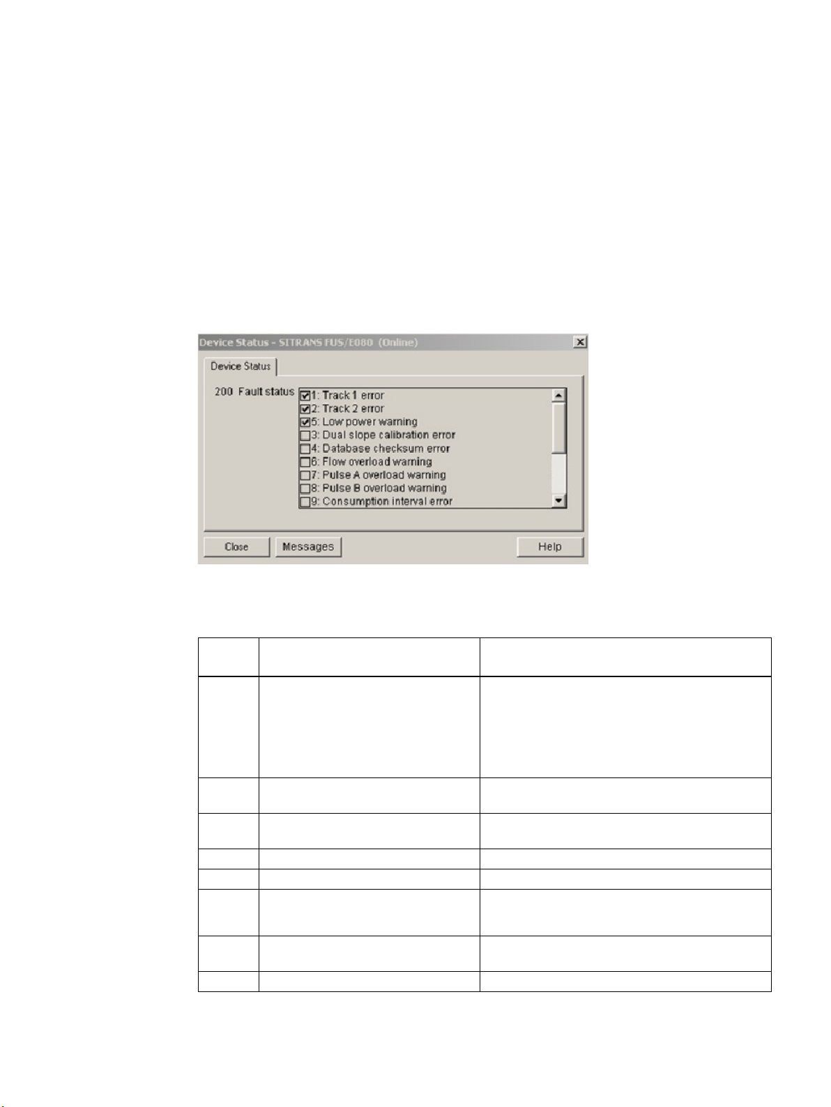
63
Troubleshooting/FAQs
9
Error
code
Error
Remedy/Cause
transducer 1A or 1B defective
F 4
Internal software failure
Contact your customer support
(max. speed 10 m/s)
9.1 Error codes
A list of errors is available in SIMATIC PDM (active errors are check-marked). Access to this
list is gained via "Device" → "Device Status". In the figure below, error codes F 1, F 2 and F 5
are active.
Figure 9-1 List of errors shown in PDM
Table 9- 1 Error codes shown in the display and in PDM
Blank
display
F 1 Path 1 (upper path) not measuring
F 2 Path 2 (lower path) not measuring
F 3 Internal software failure Contact your customer support
F 5 Power supply warning
F 6
F 7 Pulse output A overflow Pulse output exceeds 100 Hz or 50% duty cycle
Battery plug not connected, or battery
empty, mains power interrupted
Flow exceeds preset flow rate in unit
• Check flowmeter version. Battery version not
able to run on mains power
• Battery empty: Replace battery pack
• Battery plug not plugged into the transmitter,
see Battery replacement (Page 53)
No water in upper part of pipe and/or cables or
No water in lower part of pipe and/or cables or
transducer 2A or 2B defective
• Mains power fails
• Replace battery pack
Flowrate too high
SONO 3500 CT
Operating Instructions, 11/2020, AQ237286479555en-010402
Page 64

CT
010402
64
Error
code
Error
Remedy/Cause
(via PDM parameter 602)
F 8 Pulse output B overflow Pulse output exceeds 100 Hz or 50% duty cycle
F 9 Datalogger warning/alarm
Errors "F 1" to "F 4" affect the performance of the meter and the flowmeter may stop
measuring.
Errors "F 1" and "F 2" disappear when the alarm condition is corrected.
Errors "F 5" to "F 9" are only warnings and do not affect the measurement, but they will
influence the outputs.
The error indications disappear when the alarm conditions are corrected and a reset via the
communication interface has been carried out.
Datalogger warning monitors whether actual consumption on Totalizer 1 is on end of log interval or
above/below the limit settings.
The warning has no influence on the flowmetering.
Check data logger values and consumption limit
Example
Error code "F 1 2" in the display indicates a combination of error codes "F 1" and "F 2".
Possible causes:
●
Empty pipe
●
Path 1 and path 2 cables defective
●
Path 1 and path 2 cables not connected
●
Transducers defective
9.2 Diagnosing with PDM
SIMATIC PDM is a suitable tool for diagnosing the device. You can use SIMATIC PDM to
read all parameters available in the transmitter to a table for analyzing offline, view
online/actual process values and online/actual diagnostic information.
Requirements
The following procedure must be completed before diagnosing:
●
Connection of Modbus interface via PC and IrDA, see Commissioning via PDM (Page 42)
●
Installation of PDM and transmitter PDM driver, see Installing EDD files (Page 43)
Operating Instructions, 11/2020, AQ237286479555en-
SONO 3500
Page 65

65
Diagnosing with PDM
Online process values are available under menu "View" → "Display".
The "Measured Track Values" tab shows the gain steps and the flow velocities for path 1 and
path 2. For 1-path applications the values for path 2 (track 2) are "0".
The gain steps depend on the pipe size and the conditions of the measuring media.
The flow velocities depend on the flow in the pipe.
SONO 3500 CT
Operating Instructions, 11/2020, AQ237286479555en-010402
Page 66
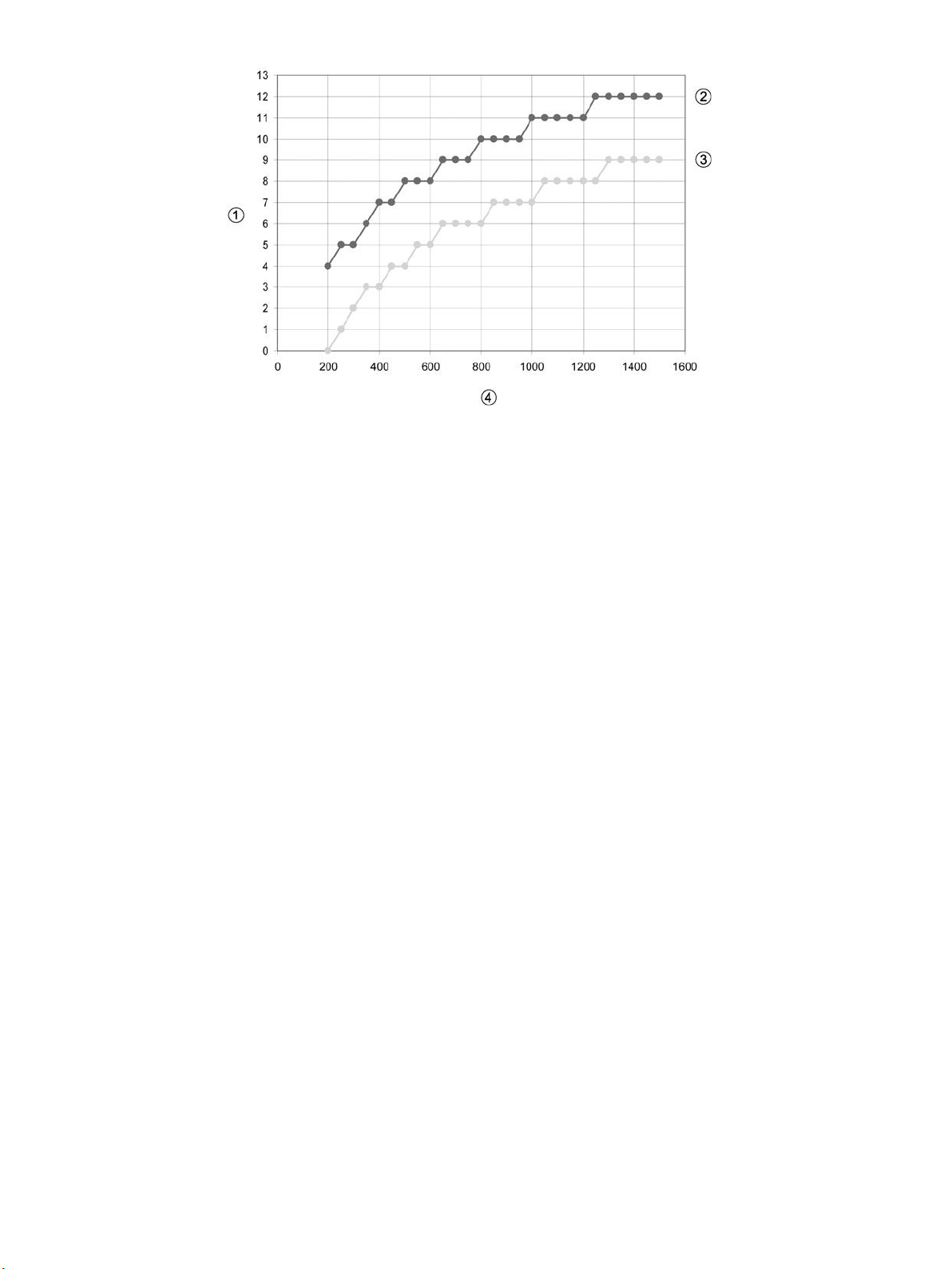
CT
010402
66
①
Gain step
②
Gain step max
③
Gain step min
④
Sensor distance [mm]
Figure 9-2 Transmitter gain step vs. Sensor distance
SONO 3500
Operating Instructions, 11/2020, AQ237286479555en-
Page 67

67
Condition
Cause
Angular misalignment
Gain step increase
2°
1
4°
3
Gain step
The graph above shows which gain step to expect for a particular transducer distance (face
to face distance). The upper curve indicates the upper limit and the lower curve indicates the
lower limit.
The graph applies to perfectly aligned transducers in clean water, but takes into account the
expected variance from the converter and the transducers.
Gain step error conditions
15
• No transducer (e.g. defective cable)
• Empty pipe
High values
• High damping (e.g. inhomogeneous media)
• Unsuitable medium
• Path angular misalignment
Unstable/fluctuating values
• Air bubbles or solids in medium
• Bad inlet conditions
Δ gain step between path 1 and path 2 > 1
(2-path systems only)
• Bad inlet conditions
• Inhomogeneous medium
• Path angular misalignment
In case of angular misalignment between transducer faces, the gain step will increase as
shown in the table below:
3° 2
5° 5
Flow velocity error conditions
Condition Cause
Δ flow velocity values (between path 1 and path
2) > 1
(2-path systems only)
Unstable/fluctuating values
• Bad inlet conditions (the higher the delta, the
worse the inlet conditions)
• Disturbances in the pipe (bad flow profile)
• Air bubbles or solids in media
• Bad inlet conditions
SONO 3500 CT
Operating Instructions, 11/2020, AQ237286479555en-010402
The actual velocities for the paths should be stable, constant and smoothly changing values
between 0 and 10 m/s.
Page 68

CT
010402
68
Technical data
10
Description
Specification
bles) and a stainless steel bracket for wall or pipe mounting
Mechanical vibration
2 g, 1 to 800 Hz sinusoidal in all directions according to IEC 68-2-6
Push button
One push button for toggling between display information
15 Hz (mains-powered)
IrDA on display panel (Modbus RTU protocol)
10.1 SONO 3500 CT
Table 10- 1 SONO 3500 CT
Enclosure design/material Fiber glass reinforced polyamide in light-gray color
Enclosure IP67 according to EN 60529 and DIN 40050 (NEMA 4X/6)
Wall mounting kit
Cable glands In wall mounting kit:
Ambient temperature -10 °C to +55 °C (14 °F to 131 °F)
Storage temperature −40 °C to + 85 °C (−40 °F to +185 °F)
Transducer/sensor cables
Power supply
Display
Terminal box made of fiber glass reinforced polyamide in light-gray
color with 2 + 2 cable glands (output, supply and transducer ca-
• 4 x M20 PA plastic cable glands (2 for mains and output cable,
2 for the transducer coaxial cables)
1)
• Coaxial cable, impedance 75 Ohm, ∅ app. 6 mm;
• Cable length: Max. 30 meter between transmitter and trans-
ducer (5 m (16.4 ft), 10 m (32.8 ft), 20 m (65.6 ft), or 30 m (98.4
ft) available)
Mains with single battery backup (always store a replacement 3.6
V LiSOCl (Lithium Thionyl Chloride) battery
• 87 to 265 V AC (50 to 60 Hz)
• LCD, 8 digits, additional 2 digits and symbols for status infor-
mation
• Units: Volume unit: m
(default display unit)
• Alarm codes (F 1 to F 9) for: path 1 or 2 not measuring, internal
failure, power supply failure, flow overload, pulse output frequency overload, data logger warning
3
(default display unit), Flow unit: m3/h
2)
):
Measuring function
Communication
• 0.5 Hz (battery mode)
•
•
SONO 3500
Operating Instructions, 11/2020, AQ237286479555en-
Page 69

69
Description
Specification
EMC performance
EN/IEC 61326-1 (Industry)
Transmitter weight
1.5 kg (3 lb)
Outputs (standard)
1)
2)
originally marketed the battery, or by the producer or importer, where the new industrial
battery is purchased.
10.2 Battery
Battery type
• Two passive, galvanically isolated open drain-mos outputs
(output A and B)
• Max. ±35 V, 50 mA
• Output A: Preset to pulse output for forward flow (default:
100 l/pulse)
• Output B: Preset to alarm for present failure
• Pulse with: 5, 10, 20, 50, 100, 200, 500 ms (default: 5 ms)
• Max. pulse frequency: 100 Hz at Qmax setting (105% of Qs)
MID: environment class -10°C to +55°C (14°F to 131°F)
Waste industrial batteries are accepted back by the producer or importer, who has
Note
Replaceable 3.6 V LiSOCl (Lithium Thionyl Chloride) single battery (16 Ah)
The battery is not rechargeable; it should be replaced at least every 6 years.
Consumption and battery operation time calculation
Every 5 minutes the advanced power management system of the transmitter calculates the
battery consumption and the remaining battery operation time.
The ambient temperature of the transmitter its also influence the battery capacity.
The typical operation time up to 6 years is based on only 80% battery capacity, low pulse
output frequency, seldom use of communication and an operation time/temperature profile of
5% at 0 °C (32 °F), 80% at 15 °C (59 °F) and 15% at 50 °C (122 °F).
The effect of other temperatures is shown in the figure below.
A variation in temperature from 15 °C to 55 °C (59 °F to 131 °F) reduces the capacity by
17% (in the figure from 15 Ah to 12½ Ah).
SONO 3500 CT
Operating Instructions, 11/2020, AQ237286479555en-010402
Page 70

CT
010402
70
Description
Specification
from factory
1000, 1200
Pressure rate
PN 16, PN 25, PN 40, EN 1092-1
Pipe materials
Carbon Steel EN 1.0345 / p235 GH, painted in light gray
Transducer design
Integrated version and welded onto the pipe
Transducer material
Stainless steel (AISI 316 / 1.4404) / brass (CuZn36Pb2As)
Media temperature
Remote: 2 to 200 °C (35.6 to 392 °F)
Note
The installation orientation of the battery may influence the battery capacity. Optimal battery
capacity is achieved with the battery in an upright position.
10.3 Sensor for SONO 3500 CT
Table 10- 2 Technical data
Pipe design
Nominal size
1)
MID: minimum temperature 15 °C (59 °F)
2-track sensor with flanges and integrated transducers wet-calibrated
DN 100, 125, 150, 200, 250, 300, 350, 400, 500, 600, 700, 800, 900,
1)
SONO 3500
Operating Instructions, 11/2020, AQ237286479555en-
Page 71

71
Size
PN 16
PN 25
PN 40 Material
A1
(mm)
Lift hug
DN
L (mm)
Weight
(kg)
L (mm)
Weight (kg)
L (mm)
Weight
(kg)
100
350 +0/-2
15 -
350 +0/-2
18
Steel
375
No
350
550 +0/-3
94
550 +0/-3
121 - -
Steel
495
Yes
400
600 +0/-3
124
600 +0/-3
153 - -
Steel
507
Yes
500
625 +0/-3
194
625 +0/-3
231 - -
Steel
558
Yes
600
750 +0/-3
303
750 +0/-3
365 - -
Steel
609
Yes
700
875 +0/-3
361
875 +0/-3
565 - -
Steel
660
Yes
800
1000 +0/-3
494
1000 +0/-3
770 - -
Steel
710
Yes
900
1230 +6/-6
475
1300 +6/-6
835
- Steel
810
Yes
1000
1300 +6/-6
594
1370 +6/-6
1078
- - Steel
910
Yes
1200
1360 +6/-6
732
- - Steel
1110
Yes
10.4 Dimensional drawings for SONO 3500 CT
Transmitter IP67/NEMA 4X/6, wall mounting
10.5 Pipe dimensions for SONO 3500 CT
125 350 +0/-2 18
150 500 +0/-3 28
200 500 +0/-3 38 500 +0/-3 47 500 +0/-3 55 Steel 414 No
250 600 +0/-3 60 600 +0/-3 76 600 +0/-3 91 Steel 440 No
300 500 +0/-3 66 500 +0/-3 81 - - Steel 466 Yes
350 +0/-3 24 Steel 380 No
500 +0/-3 34 Steel 390 No
SONO 3500 CT
Operating Instructions, 11/2020, AQ237286479555en-010402
Page 72

CT
72
Size
PN 16
PN 25
PN 40
Material
A1
(inch)
Lift hug
inch
L (inch)
Weight
(lb)
L (inch)
Weight
(lb)
L (inch)
Weig
ht (lb)
4
13.78 +0/-0.08
33 - -
13.78+0/-0.08
40
Steel
14.76
No
5
13.78 +0/-0.08
40 - -
13.78+0/-0.08
53
Steel
14.96
No 6 19.68 +0/-0.12
62 - -
19.68+0/-0.12
75
Steel
15.35
No 8 19.68 +0/-0.12
84
19.68 +0/-0.12
104
19.68+0/-0.12
121
Steel
16.30
No
10
23.62 +0/-0.12
132
23.62 +0/-0.12
168
23.62+0/-0.12
201
Steel
17.32
No
12
19.68 +0/-0.12
146
19.68 +0/-0.12
179 - -
Steel
18.35
Yes
14
21.65 +0/-0.12
207
21.65 +0/-0.12
267 - -
Steel
19.49
Yes
16
23.62 +0/-0.12
273
23.62 +0/-0.12
337 - -
Steel
19.96
Yes
20
24.61 +0/-0.12
428
24.61 +0/-0.12
509 - -
Steel
21.97
Yes
-
24 29.53 +0/-0.12 668 29.53 +0/-0.12 805 - - Steel 23.98 Yes
28 34.45 +0/-0.12 796 34.45 +0/-0.12 1246 - - Steel 25.98 Yes
32 39.37 +0/-0.12 1089 39.37 +0/-0.12 1698 - - Steel 27.95 Yes
36 48.43 +/-0.24 1047 51.18 +/-0.24 1841 -
40 51.18 +/-0.24 1310 53.94 +/-0.24 2205 - - Steel 35.83 Yes
48 53.54 +/-0.24 1614 -
Steel 31.89 Yes
Steel 43.70 Yes
Weight for transmitter/electronics 1.5 kg (3.3 lb)
For flange values - see norm EN 1092-1
- means not available.
SONO 3500
Operating Instructions, 11/2020, AQ237286479555en-010402
Page 73

73
Parameter lists
A
Parameter
Default value
Value range
Access
level
Description
mation (max 16 characters)
(max 16 characters)
Device
at pipe date in parameter 306
Note:
online via PDM
The following tables show the various parameters available via SIMATIC PDM.
The parameters are accessible at three different levels:
●
Read: Maintenance level
●
Read/Write (R/W): Specialist level (write access is only permitted after entering the user
password; default password is 1000)
●
Hardware locked (HW key): The parameter is only accessible when a HW key is mounted
Note
For type-approved and verified SONO 3500 CT flowmeter the settings are HW key protected
and therefore read only. This HW key is protected via the verification sealing. The verification
sealing can only be broken by the user with the acceptance of the local authorities.
A.1 Identification
Table A- 1 Identification parameters (FW 2.03 and EDD 1.02.07-01)
1 Application identifier Identity
2 Application location Location
5 Sensor size
Product dependent
R/W
R/W
R/W
Customer application identification infor-
Customer application location information
Pipe diameter of the sensor. It is only a
text field for measurement system information. The value has no influence on the
measurement. Please see inner diameter
8 Totalizer unit m
SONO 3500 CT
Operating Instructions, 11/2020, AQ237286479555en-010402
3
See Unit conversion table
(Page 83)
R/W
Totalizer unit as text for volume. Change
the unit in parameter table if the device
menu "Unit guide (offline)" does not list the
wanted unit.
The device display can show "m3"
unit only - other units cannot be shown on
the display, but will be used and shown
Page 74

CT
010402
74
Parameter
Default value
Value range
Access
level
Description
online via PDM.
10
Maximum flow
Qmax
R/W
Maximum flow
plate)
pendent
system number on the nameplate
ber
pendent
pendent
Qmax, then the flow value is set to zero
Parameter
Default
value
Value range
Access
level
Description
dependent
and hours:minutes:seconds)
+2000000001
+2000000001
set up
104
Reset customer totalizer 3
No
No, Yes
R/W
Reset of customer totalizer
date
date
hh:mm:ss
has been reset
9 Flowrate unit m3/h
See Human
Interface
(Page 83)
R/W
Flow unit as text for actual flowrate.
Change the unit in parameter table if the
device menu "Unit guide (offline)" does not
list the wanted unit.
Note: The device display can show "m
unit only - other units cannot be shown on
the display, but will be used and shown
373 Low flow cut-off 0.25 0 ... 10 R/W
If the flow comes below this percentage of
Qmax, then the flow value is set to zero
20 Vendor name Danfoss A/S
Read Danfoss A/S, Denmark
21 Module type 11 0 ... 14 Read Type of flowmeter
22 Software version 2.03
23 Product code number
Product dependent
24 System Serial number
25
Transmitter serial num-
26 Sensor serial number
Product de-
Product de-
Product de-
R/W
HW key Serial number of the electronics
373 Low flow cut-off 0.25 0 ... 10 R/W
Software version of the flowmeter
Production sales code number (the first
part of the system number on the name-
Production number (the second part of the
Serial number of the sensor
If the flow comes below this percentage of
3
/s"
A.2 Output
Table A- 2 Output parameters
100 Actual date and time
101 Totalizer 1 0
102 Totalizer 2 0
103 Customer totalizer 3 0
Customer totalizer 3 reset
105
Product
last reset
-2000000001 ...
-2000000001 ...
dd-mm-yyyy,
R/W
Actual date and time (day-month-year
Read Volume for totalization register 1
Read Volume for totalization register 2
Read
Customer totalizer 3 based on totalizer 1
Date and time when customer totalizer
SONO 3500
Operating Instructions, 11/2020, AQ237286479555en-
Page 75

75
Parameter
Default
value
Value range
Access
level
Description
107
Relative flow rate
0 Read
Actual flow value in relation to Qmax
(SI-unit)
Valid for 2-path solutions only
110
Path 1 gain step
15
1 to 15
Read
Amplifier setting when measuring path 1
Valid for 2-path solutions only
Pulse A B
Valid if pulse output A is enabled
Valid if pulse output A is enabled
440
Output B enable
Yes
No, Yes
R/W
Select "Yes" to enable output B
pulse function selected
pulse function selected
pulse function selected
Communication
dress
selectable address up to 247
592
Baudrate
4
0 ... 5
Read
Communication port speed
(bytes x 10)
to its response
106 Flow rate
108 Actual velocity for path 1 0
109 Actual velocity for path 2 0
Read Actual flow value
Read
The actual flow velocity for path 1 in m/s
The actual flow velocity for path 2 in m/s
(SI-unit).
111 Path 2 gain step 15 1 to 15 Read
Amplifier setting when measuring path 2.
430 Output A enable Yes No, Yes R/W Select "Yes" to enable output A
431 Pulse A function Forward
432 Amount per pulse A
1.000000
3
(m
)
433 Pulse width for pulse A 5 ms
Forward, Reverse, Forward
net, Reverse net
0.000001 ...
1000000000
5, 10, 20, 50,
R/W
R/W
R/W
Pulse output calculation on pure forward
flow or pure reverse flow - or net flow for
forward and reverse pulse flow.
Volume per pulse and selected unit
Valid if pulse output A is enabled.
Pulse length when the pulse is active.
100, 200, 500 ms
441 Pulse B function Alarm
Pulse, Alarm,
Call up
R/W
Configuration of output B as pulse alarm or call up function.
Valid if pulse output B is enabled
442 Pulse B direction Reverse
Forward, Reverse, Forward
net, Reverse net.
R/W
Pulse output calculation on pure forward
flow or pure reverse flow - or net flow for
forward and reverse pulse flow.
Valid if pulse output B is enabled and
443 Amount per pulse B
444 Pulse width for pulse B 5 ms
For editing the communication settings, use PDM device menu "Communication Setting"
Device Communication Ad-
591
593 Parity 0 0 ... 3 Read Communication port parity
594 Interframe space 35 35 ... 255 Read
595 Response delay 5 1 ... 50 Read
SONO 3500 CT
Operating Instructions, 11/2020, AQ237286479555en-010402
1.000000
3
(m
)
0.000001 ...
1000000000
5, 10, 20, 50,
R/W
R/W
100, 200, 500 ms
1 1 ... 247 Read
Volume per pulse.
Valid if pulse output B is enabled and
Pulse length when the pulse is active.
Valid if pulse output B is enabled and
Meter has default address value 1 with
Minimum space between two messages
Minimum time from receiving a request
Page 76

CT
010402
76
Parameter
Default
value
Value range
Access
level
Description
Data logger
Monthly
and the selected unit
and the selected unit
Periodic log Totalizer 1
2000
totalizer 1 is stored
2000
izer 1 was stored
2000
totalizer 1 was stored
164
Previous totalizer 1 value
0
dd-mm-yyyy
Read
Previously stored value of totalizer 1
Parameter
Default
value
Value
range
Access
level
Description
Diagnostic
er up
er-up.
600 Log interval Monthly
601 Day of week, if weekly log Sunday
Limit for too high consump-
602
tion
Limit for too low consump-
603
tion
604 Reset log
160 Next settling date
161 Latest settling date
162 Latest totalizer 1 value 0
163 Previous settling date
1E+09
No
01-01-
01-01-
01-01-
Daily, Weekly,
Monday to Sunday
R/W Log interval
R/W
When log interval is set to weekly logging, this parameter defines what weekday the logging is performed.
Valid if weekly log interval is activated
-3.4E+38 ...
+3.4E+38
-3.4E+38 ...
+3.4E+38
R/W
R/W
Limit for too low consumption during
current log interval. Based on totalizer 1
Limit for too low consumption during
current log interval. Based on totalizer 1
No, Yes HW key Reset data logger
dd-mm-yyyy R/W
dd-mm-yyyy Read
Next settling date where actual value of
Latest settling date where value of total-
Read Latest stored value of totalizer 1
Read
Previous settling date where value of
A.3 Diagnostic
Table A- 3 Diagnostic
500 Latest service date 01-01-2000
501
503 Numbers of power up 0 0 ... 65535 Read
Operating hours since pow-
dd-mmyyyy
R/W
Latest service date (can also be used for
date of installation)
0 3.4E+38 h Read Total operation hours since last power up
Total number of power-ups since first pow-
SONO 3500
Operating Instructions, 11/2020, AQ237286479555en-
Page 77

77
Parameter
Default
value
Value
range
Access
level
Description
Alarm
hh:mm:ss
faults
205
Call up acknowledge
No
No, Yes
R/W
Select "Yes" to reset active call-up
in the log interval
alarm output / call-up
211
Path 1 fault hours
e.g. 36 h
Read;
Total hours fault active
hh:mm:ss
date
hh:mm:ss
Select "Yes" to enable active alarm on alarm
Valid only for 2-path solutions
200 Fault status
202 Date of fault log reset
204
Reset the fault log and
One or
more of the
following
values: 1, 2,
3, 4, ... up
to 16
Last reset
date
No No, Yes R/W Reset the fault log and faults
dd-mmyyyy,
Read
Read Date of last fault log reset
Fault status
1: Path 1 error
2: Path 2 error
3: Dual slope calibration error
4: Database checksum error
5: Low power warning
6: Flow overload warning
7: Pulse A overload warning
8: Pulse B overload warning
9: Consumption interval error
10: Not used
11: Not used
12: Not used
13: Not used
14: Not used
15: Not used
16: Not used
209 Reset consumption log fault No No, Yes R/W
210 Path 1 alarm output enable Yes No, Yes R/W
212 Path 1 fault counter e.g. 4 0 ... 65535 Read
213 Path 1 fault appears
214 Path 1 fault disappears
215 Path 2 alarm output enable Yes No, Yes R/W
216 Path 2 fault hours e.g. 36 h Read; Read
Last fault
appear date
Last fault
disappear
dd-mmyyyy,
dd-mmyyyy,
Read
Read
Reset the consumption fault.
Caused by too low or too high consumption
Select "Yes" to enable current alarm on
Total number of faults.
Valid only if alarm is enabled
Last time the fault appeared.
Valid only if alarm is enabled
Last time the fault disappeared.
Valid only if alarm is enabled
output / call-up.
Total hours fault active.
Valid only for 2-path solutions and if alarm is
enabled
SONO 3500 CT
Operating Instructions, 11/2020, AQ237286479555en-010402
Page 78

CT
010402
78
Parameter
Default
value
Value
range
Access
level
Description
enabled
enabled
enabled
enable
output / call-up
Valid only if alarm is enabled
output enable
output / call-up
Valid only if alarm is enabled
counter
enabled
Valid only if alarm is enabled
enable
output / call-up
Valid only if alarm is enabled
Valid only if alarm is enabled
Flow overflow alarm output
enable
Select "Yes" to enable active alarm on alarm
output / call-up
217 Path 2 fault counter e.g. 4 0 ... 65535 Read
218 Path 2 fault appears
219 Path 2 fault disappears
220
221 Dual slope fault hours e.g. 0 h 0 ... 65535 Read
222 Dual slope fault counter e.g. 0 0 ... 65535 Read
223 Dual slope fault appears e.g. 0 h 0 ... 65535 Read
224 Dual slope fault disappears e.g. 0 0 ... 65535 Read
225
226
Dual slope alarm output
Parameter checksum alarm
Parameter checksum fault
hours
Last fault
appear date
Last fault
disappear
date
Yes No, Yes R/W
Yes No, Yes R/W
e.g. 0 h 0 ... 65535 Read
dd-mmyyyy,
hh:mm:ss
dd-mmyyyy,
hh:mm:ss
Read
Read
Total number of faults.
Valid only for 2-path solutions and if alarm is
First time the fault appeared.
Valid only for 2-path solutions and if alarm is
Last time the fault disappeared.
Valid only for 2-path solutions and if alarm is
Select "Yes" to enable active alarm on alarm
Total hours fault active.
Valid only if alarm is enabled
Total number of faults.
Valid only if alarm is enabled
First time the fault appeared.
Last time the fault disappeared.
Valid only if alarm is enabled
Select "Yes" to enable active alarm on alarm
Total hours fault active.
227
228
229
230
231 Low power fault hours e.g. 0 h 0 ... 65535 Read
232 Low power fault counter e.g. 0 0 ... 65535 Read
233 Low power fault appears e.g. 0 h 0 ... 65535 Read
234 Low power fault disappears e.g. 0 0 ... 65535 Read
235
236 Overflow fault hours e.g. 0 h 0 ... 65535 Read
Parameter checksum fault
Parameter checksum fault
appears
Parameter checksum fault
disappears
Low power alarm output
e.g. 0 0 ... 65535 Read
e.g. 0 h 0 ... 65535 Read
e.g. 0 0 ... 65535 Read
Yes No, Yes R/W
Yes No, Yes R/W
Total number of faults. Valid only if alarm is
First time the fault appeared.
Password to change parameters in the
flowmeter.
Valid only if alarm is enabled
Select "Yes" to enable active alarm on alarm
Total hours fault active.
Valid only if alarm is enabled
Total number of faults.
First time the fault appeared.
Valid only if alarm is enabled
Last time the fault disappeared.
Total hours fault active.
Valid only if alarm is enabled
SONO 3500
Operating Instructions, 11/2020, AQ237286479555en-
Page 79

79
Parameter
Default
value
Value
range
Access
level
Description
Valid only if alarm is enabled
output enable
output / call-up
Valid only if alarm is enabled
Valid only if alarm is enabled
Valid only if alarm is enabled
output enable
output / call-up
Valid only if alarm is enabled
Valid only if alarm is enabled
enable
output / call-up
Valid only if alarm is enabled
Valid only if alarm is enabled
ble
output / call-up
Valid only if alarm is enabled
237 Overflow fault counter e.g. 0 0 ... 65535 Read
238 Overflow fault appears e.g. 0 h 0 ... 65535 Read
239 Overflow fault disappears e.g. 0 0 ... 65535 Read
240
241 Pulse A overload fault hours e.g. 0 h 0 ... 65535 Read
242
243
244
245
246 Pulse B overload fault hours e.g. 0 h 0 ... 65535 Read
247
Pulse A overload alarm
Pulse A overload fault counter
Pulse A overload fault appears
Pulse A overload fault disappears
Pulse B overload alarm
Pulse B overload fault counter
Yes No, Yes R/W
e.g. 0 0 ... 65535 Read
e.g. 0 h 0 ... 65535 Read
e.g. 0 0 ... 65535 Read
Yes No, Yes R/W
e.g. 0 0 ... 65535 Read
Total number of faults.
Valid only if alarm is enabled
First time the fault appeared.
Last time the fault disappeared.
Valid only if alarm is enabled
Select "Yes" to enable active alarm on alarm
Total hours fault active.
Total number of faults.
First time the fault appeared.
Last time the fault disappeared.
Valid only if alarm is enabled
Select "Yes" to enable active alarm on alarm
Total hours fault active.
Valid only if alarm is enabled
Total number of faults.
248
249
250
251 Consumption fault hours e.g. 0 h 0 ... 65535 Read
252 Consumption fault counter e.g. 0 0 ... 65535 Read
253 Consumption fault appears e.g. 0 h 0 ... 65535 Read
254
255
256 Leakage fault hours e.g. 0 h 0 ... 65535 Read
257 Leakage fault counter e.g. 0 0 ... 65535 Read
Pulse B overload fault appears
Pulse B overload fault disappears
Consumption alarm output
Consumption fault disappears
Leakage alarm output ena-
e.g. 0 h 0 ... 65535 Read
e.g. 0 0 ... 65535 Read
Yes No, Yes R/W
e.g. 0 0 ... 65535 Read
Yes No, Yes R/W
First time the fault appeared.
Last time the fault disappeared.
Valid only if alarm is enabled
Select "Yes" to enable active alarm on alarm
Total hours fault active.
Valid only if alarm is enabled
Total number of faults.
First time the fault appeared.
Valid only if alarm is enabled
Last time the fault disappeared.
Select "Yes" to enable active alarm on alarm
Total hours fault active.
Valid only if alarm is enabled
Total number of faults.
SONO 3500 CT
Operating Instructions, 11/2020, AQ237286479555en-010402
Page 80

CT
010402
80
Parameter
Default
value
Value
range
Access
level
Description
Valid only if alarm is enabled
enable
output / call-up
Valid only if alarm is enabled
Valid only if alarm is enabled
Valid only if alarm is enabled
Valid only if alarm is enabled
Service
Always manually reset the value to "No"
Valid if pulse output is enabled
Power
er up
er-up.
date
hh:mm:ss
cannot be changed.
258 Leakage fault appears e.g. 0 h 0 ... 65535 Read
259 Leakage fault disappears e.g. 0 0 ... 65535 Read
260
261 Empty pipe fault timer e.g. 0 h 0 ... 65535 Read
262 Empty pipe fault counter e.g. 0 0 ... 65535 Read
263 Empty pipe fault appears e.g. 0 h 0 ... 65535 Read
264 Empty pipe fault disappears e.g. 0 0 ... 65535 Read
510 Fixed flow mode enable Yes No, Yes R/W
511 Fixed flow value 0
515 Controlling output A and B Auto
Empty pipe alarm output
Yes No, Yes R/W
-1E+09 ...
1E+09
Auto,
Forced
R/W Fixed flow value for enabled fixed flow
HW key
First time the fault appeared.
Valid only if alarm is enabled
Last time the fault disappeared.
Select "Yes" to enable active alarm on alarm
Total hours fault active.
Total number of faults.
First time the fault appeared.
Last time the fault disappeared.
Select "Yes" to force the device to show a
fixed flow value
Default must be "No"
Control of output A and B is used to stop or
force the output A and/or B.
For editing, use device menu "Service".
130 Consumed battery capacity
501
503 Numbers of power up e.g. 4 0 ... 65535 Read
540 Battery change enable No No, Yes R/W
541 Battery installation date
542 Power supply mode Battery only
Operating hours since pow-
e.g.
2.054239
Ah
1105 h 3.4 E+38 Read Total operation hours since first power up
last battery
installation
dd-mmyyyy;
Battery
only, Mains
only, Mains
with backup
battery.
Read
Read
Read
Operating Instructions, 11/2020, AQ237286479555en-
The amount of energy consumed since last
time the battery was replaced.
Valid only for battery-powered versions
Total number of power-ups since first pow-
Select "Yes" to set battery installation date
to current date and reset remaining battery
operation capacity to maximum.
Valid only for battery-powered versions
Latest installation date of batteries.
Valid only for battery-powered versions
The flowmeter is either powered by battery
only, mains only or by mains with battery
backup.
The type is defined by the order code and
SONO 3500
Page 81

81
Parameter
Default
value
Value
range
Access
level
Description
Valid only for battery-powered versions
Parameter
Default
value
Value
range
Access
level
Description
Meter Setup
m/s
flow rate
dependent
signal.
the device menu "Linearization"
543 Actual battery capacity 25.000000 0 ... 50 R/W**
544 Battery alarm limit 80 0 ... 90 R/W
** Maintenance = Read only
A.4 Meter setup
Table A- 4 Meter setup parameters
307 Flow velocity offset 0 m/s
310 Calibration factor 1.0 0 ... 2 R/W
311 Adjustment Factor 1 - 2 ... 2 R/W
-10 ... 10
The capacity of the battery in Ah
- Single 12.5 Ah
- Dual battery pack 25.0 Ah
Valid only for battery-powered versions
Present an alarm when the consumed energy exceeds this percentage of the battery
capacity.
HW key Velocity added to measured flow velocity
This calibration factor will be calculated at
the factory with wet-calibration.
Meter correction factor for customer adjustment of the calculated flow value. Can
be used at installations where a reference
meter is used to get reference to the true
312 Transducer cable length
372 Filter time constant
380
Protect linearization from
user access.
SONO 3500 CT
Operating Instructions, 11/2020, AQ237286479555en-010402
Product
Product
0 ... 200 m R/W Cable length (m) from sensor to transmitter
0 ... 100 s R/W
dependent
No No, Yes Read
General time filter for flow measurement.
Filter constant is the time that must pass
before the filter's output value is at 70% of
the change of its input value. Higher number gives a slower and more stable flow
Protection of the linearization parameters. It
is decided by the order number and cannot
be changed.
The linearization parameters are listed in
Page 82

CT
010402
82
Parameter
Default
value
Value
range
Access
level
Description
Totalizer
Net
hh:mm:ss
Net
hh:mm:ss
Pipe data
dependent
ment
ured
dependent
dependent
dependent
1.200 m
400 Flow direction totalizer 1 Forward
401 Totalizer 1 change date
410 Flow direction totalizer 2 Reverse
411 Totalizer 2 change date
300 Number of paths
302 Max sample frequency 15 15 Read
303 Sample frequency 0.5 15 HW key
304 Rn for path 1
305 Rn for path 2
306 Inner pipe diameter
Last change
date
Last change
date
Product
Product
Product
Product
Forward,
Reverse,
dd-mmyyyy;
Forward,
Reverse,
dd-mmyyyy;
2 R/W Number of paths on the sensor
3.4E+38 m Read R-factor for path 1.
3.4E+38 m Read R-factor for path 2.
0.05 ...
R/W
Read
R/W
Read
Read Inner pipe diameter in meters.
Calculation principle on flow direction for
forward, reverse or net flow
Date and time when totalizer 1 function was
changed
Calculation principle on flow direction for
forward - reverse or net flow
Date and time when totalizer 2 function was
changed
The maximum frequency for flow measure-
The frequency at which the flow is meas-
SONO 3500
Operating Instructions, 11/2020, AQ237286479555en-
Page 83

83
Parameter
Default
value
Value range
Access
level
Description
adjust.
1. Totalizer 1
2. Totalizer 2
3. Actual flow rate
4. Error menu
For editing, use device menu "Human
Interface"
Unit
Correction factor
Gallon (US)
264.1721
G*1000 (1000*Gallon)
0.2641721
AI (Acre Inches)
0.009728558
CF*100 (100*ft3)
0.3531467
CF*1000 (1000*ft3)
0.03531467
I*100 (liter)
10
kI (1000*liter)
1
MI (Mega liter)
0.001
A.5 Human Interface
Table A- 5 Human Interface parameters
420 Decimal point
Automatic
point adjust
422 Operator Menu 1 All 1 to 5
A.6 Unit conversion table
The following tables show examples of totalizer and flow rate units. More are available via
SIMATIC PDM tool
Table A- 6 Totalizer units
No point; One
digit after
point; Two
digits after
point; Three
digits after
point; Automatic point
R/W
Read
only
Decimal numbers for displayed totalized
value
Menu setup
5. Display test menu
SONO 3500 CT
Operating Instructions, 11/2020, AQ237286479555en-010402
Default 1 m
3
m3*100 0.01
G*100 (100*Gallon) 2.641721
MG (1000000*Gallon) 0.0002641721
AF (Acre ft) 0.0008107132
Page 84

CT
010402
84
Flow rate
Correction factor parameter
m3/min (m3/minute)
60
m3/d (m3/day)
86400
GPS (Gallon/second)
264.1721
GPM (Gallon/minute)
15850.32
GPH (Gallon/hour)
951019.4
GPD (Gallon/day)
22824465
MGPD (1000000*Gallon/day)
22.824465
CFS (ft3/second)
35.31467
I/s (liter/second)
1000
I/h (liter/hour)
3600000
Table A- 7 Flow rate units
Default 1 m3/s
m3/h (m3/hour) 3600
CFM (ft3/minute) 2118.882
CFH (ft3/hour) 127132.8
I/min (liter/minute) 60000
MI/d (1000000lLiter/day) 86.4
SONO 3500
Operating Instructions, 11/2020, AQ237286479555en-
Page 85

85
Settings
B
1200)
Application location
-
Free text 15 characters
Pipe data
Number of paths
2
1 or 2
configured according the order code
ing the selection via the order code.
nameplate).
used)
configured according the order code
gram in PDM
configured according the order code
gram in PDM
Correction factor
Costumer correction factor
1
0.5 … 1.5
B.1 Factory settings
The transmitter is from factory configured according to the order specification.
For the calibration / configuration of the flowmeter the application specific pipe dimensions
and the specific transducer locations can require an update.
Note
For type-approved and verified SONO 3500 CT flowmeter the settings are HW key protected
and therefore read only. This HW key is protected via the verification sealing. The verification
sealing can only be broken by the user with the acceptance of the local authorities.
Table B- 1 Factory settings
Identification
Meter identification - Free text 15 characters
Display menu Menu 1 – 5 (all) Menu 1 – 5, min one of the five
Inner pipe diameter (m)
Q max
Low flow cut-off (% of Qmax)
Filter time constant
2-path factory settings (DN 50 to DN
for SONO 3500 CT factory pre-
Qmax is 105% of Qs (Qs is shown on
the system nameplate). For SONO
3500 CT factory pre-configured accord-
0.25 %
For SONO 3500 CT factory pre-
configured. It is %-value related to the
Qmax setting. The %-value is equal to
50% of Qi (Qi is shown on the system
Factory pre-configured to typical 5 s
(for larger pipe size higher values are
Possible settings
may not be changed
Adjustable
Adjustable between 0 … 10%
Adjustable between 5 … 1000 s
Geometry factor path 1
Geometry factor path 2
SONO 3500 CT
Operating Instructions, 11/2020, AQ237286479555en-010402
For SONO 3500 CT factory pre-
For SONO 3500 CT factory pre-
Auto set from pipe geometry help pro-
Auto set from pipe geometry help pro-
Page 86

CT
010402
86
Measuring unit and factors
Totalizer volume unit factor
1
Auto set from unit guide
can be shown on display
can be shown on display
Totalizer directions
net
net
Digital output 1
Active
On
On/off
net
Value freely selectable
Pulse width
5 ms
5, 10, 20, 50, 100, 200, 500 ms
Digital Output 2
Active
On
On/off
net
Pulse width
No influence, while "Alarm"
5, 10, 20, 50, 100, 200, 500 ms
Parameter
Default setting
Flow unit factor 3600 (for flow unit m3/h) Auto set from unit guide
3
Flow unit text m3/h
Auto set from unit guide, but only m
/h
3
Totalizer unit text
m
Totalizer 1 direction Forward
Totalizer 2 direction Reverse
Direction Forward
Amount per pulse 0.1 m
3
Auto set from unit guide, but only m
Forward/Reverse/Forward net/Reverse
Forward/Reverse/Forward net/Reverse
Forward/Reverse/Forward net/Reverse
Unit: The same as Totalizer unit
Function Alarm Pulse/Alarm/Call up
Direction No influence, while "Alarm"
Amount per pulse No influence, while "Alarm"
Forward/Reverse/Forward net/Reverse
Unit: The same as Totalizer unit
Value freely selectable
3
B.2 Factory settings for Modbus communication
Slave device address 1
Data transmission rate 19 200 baud
Parity Even
Stop bit 1
Response timeout 10000 ms
Response delay 5 ms
Interframe space 35 bits
The settings can be changed by way of SIMATIC PDM or through the Modbus communication. To
support the option with current output module the s in the preceding table are recommended.
SONO 3500
Operating Instructions, 11/2020, AQ237286479555en-
Page 87

87
SONO 3500 CT
Operating Instructions, 11/2020, AQ237286479555en-010402
Page 88

For more information
www.danfoss.com
Danfoss A/S
Heating Segment • heating.danfoss.com • +45 7488 2222 • E-Mail: heating@danfoss.com
Danfoss can accept no responsibility for possibl e errors in cata logues, brochures and other prin ted material. Danfoss reserves t he right to alter its products withou t notice. This also applies to
products already on order provided that such alterations can be made without subsequential changes being necessary in specifications already agreed.
 Loading...