

Page 1
Application Note
Siemens S7 PLC and FC 300 Profibus
VLT® AutomationDrive FC 300
Page 2
Siemens S7 PLC and FC 300 Profibus
www.infoPLC.net
Introduction
This application note describes how to set
up a PROFIBUS system between a Danfoss
Drives FC 300 frequency converter and S7
PLC 315-2 from Siemens.
It is assumed that you are already familiar
with the Simatic S7 system.
Only the steps which are required in order
to establish communication between the FC
300 Profibus and the Simatic S7-315-2 DP
PLC are shown.
NOTE!:
The examples do not describe all the
functions needed for a real application, for
example error handling.
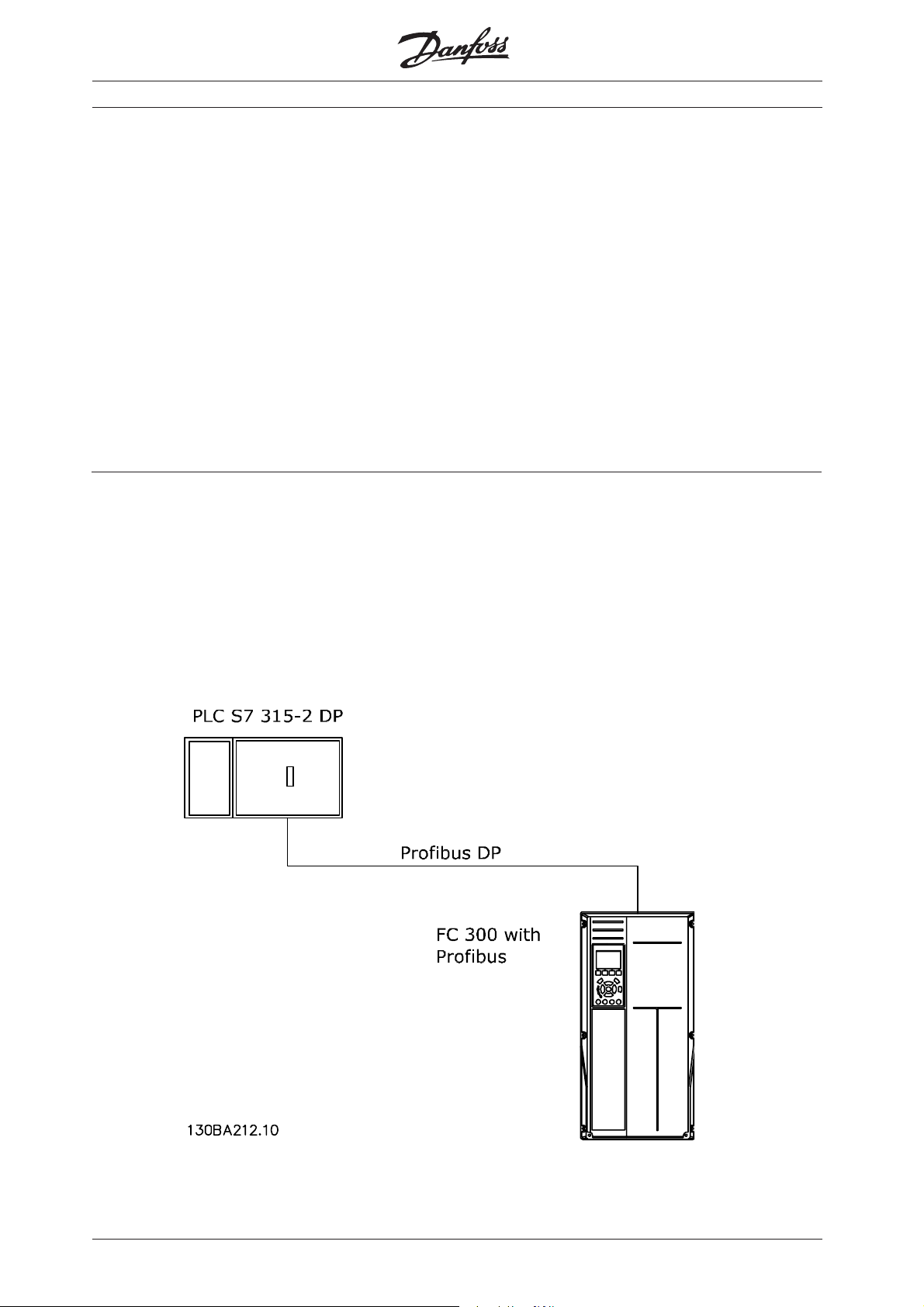
System description
The drawing shows the system in this
application note.
On the PROFIBUS network the stations are
programmed in the following way:
S7 PLC 315-2 DP: Address number 1.
FC 300: Address number 5 PPO Type 2
Module consistent.
This note describes:
System description
Configuring the Profibus network
Downloading and troubleshooting
Check of communication
Simatic project for download
Details of some of the components/
software:
FC 300 with PROFIBUS interface - sw.
version 2.xx.
FC 300 GSD version 2.00
PLC S7-315-2 DP (6ES7 315-2AG10-0AB0 /
V2.0)
SIMATIC Manager version 5.3 + SP1
MN.33.A1.02 - VLT is a registered Danfoss trademark
1
Page 3

Configuring the Profibus network
www.infoPLC.net
Start the SIMATIC Manager and create a
new project.
Open Hardware configuration in S7 Manager
to configure the system.
Siemens S7 PLC and FC 300 Profibus
In order to configure a PROFIBUS system,
the configuration tool needs a GSD file for
each type of slave on the network. The
GSD file is a PROFIBUS DP "standard" text
file containing the necessary communications setup data for a slave.
Download the necessary GSD files at
http://www.danfoss.com/BusinessAreas/
DrivesSolutions
The first step in configuration of the
PROFIBUS Master is to import the GSD file in
the configuration tool. The steps outlined
below show how to add a new GSD file to
the Simatic Manager software tool. For
each drive series, a GSD file is typically
imported once only, following the initial
installation of the software tool.
Using the browser for the GSD file, choose
to install the needed GSD files. Both the
GSD file and a bitmap for the device will be
imported into the Hardware catalogue.
2
MN.33.A1.02 - VLT is a registered Danfoss trademark
Page 4
Configuring the Profibus network
www.infoPLC.net
The GSD file is now imported and will be
accessible via the following path in the
Hardware catalogue.
Note that the GSD revision should display a
revision higher than 2.00.
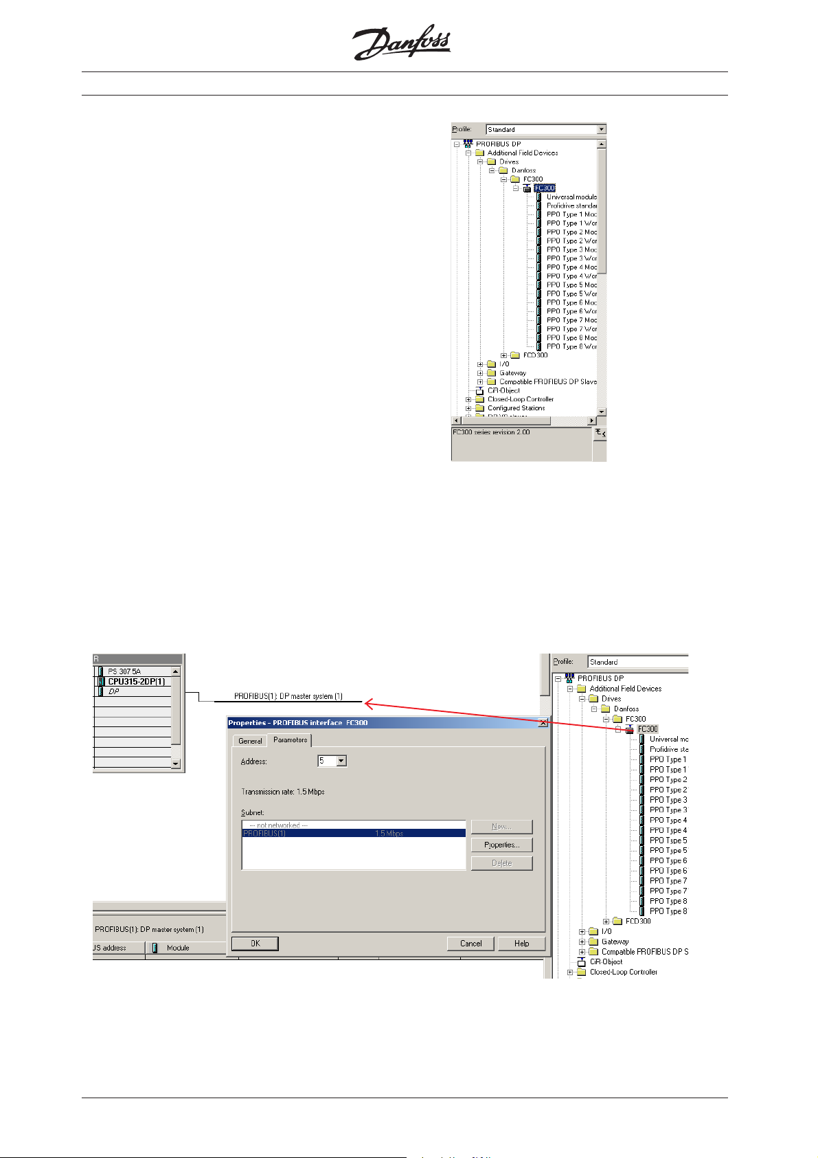
Insert a Profibus network and add a
PROFIBUS Master system. Setup the
Profibus network to a baud rate from 9.6
kbaud to 12 Mbaud.
Select FC 300 from the Hardware catalogue
and drag and drop it to the PROFIBUS
network.
A window for the address of the FC 300
now appears. Select the address from the
scroll-down list. Note that this address
setting must match the address setting in
par. 9-18 Node address.
Siemens S7 PLC and FC 300 Profibus
MN.33.A1.02 - VLT is a registered Danfoss trademark
3
Page 5

Siemens S7 PLC and FC 300 Profibus
www.infoPLC.net
Configuring the Profibus network
The next step is to set up the peripheral
input and output data via a PPO type. In
the peripheral area data is transmitted
cyclically via PPO types. In the example
below, a PPO type 2 Module consistent is
dragged and dropped to the first slot.
The choice of PPO type is made in the
master configuration, and is then automatically recorded in the frequency converter.
No manual setting of PPO types in the FC
300 is required.
The current PPO type can be read in par.
9-22 Telegram selection.
In addition, all PPO types can be set up as
word consistent or module consistent.
For FC 300, the process data area can be
word or module consistent, whereas the
parameter channel must always be module
consistent. Module consistent data is
transmitted as sets of interrelated words
transferred simultaneously between the PLC
program and the Profibus master. Word
consistent data is transmitted as individual
independent words between the PLC and
the Profibus master.
4
MN.33.A1.02 - VLT is a registered Danfoss trademark
Page 6

Siemens S7 PLC and FC 300 Profibus
www.infoPLC.net
Configuring the Profibus network
The system is now set up to use the PPO
type 2 in the following peripheral I/O area:
Process data, i.e. write a Control word and
Parameter Characteristic (PCA), i.e. read
and write to parameters.
Master to Slave
Parameter channel (PCA) Process channel (PCD)
PCD 1 PCD 2 PCD 3 PCD 4 PCD 5 PCD 6
PCA Index High
PVA
PQW
256
PQW
258
PQW
260
Low
PVA
PQW
262
Control
word
PQW 264 PQW 266 PQW 268 PQW
Reference Torque
Reference and receiving a Status word and
Main Actual Value.
limit
Ramp 1
up time
270
Empty Empty
PQW
272
PQW
274
Slave to Master
Parameter channel (PCA) Process channel (PCD)
PCD 1 PCD 2 PCD 3 PCD 4 PCD 5 PCD 6
PCA Index High
PVA
PIW
256
PIW
258
PIW
260
Low
PVA
PIW
262
Status
word
PIW 264 PIW 266 PIW
Main Actual
Value
Motor
current
268
Frequency Digital
input
PIW 270 PIW
272
Empty
PIW
274
PQW means the data from the Master to
the Slave. By PCA the output data will
contain the request of a parameter read or
write. By Process data the first word of
output data is the Control word of the FC
300 and the next is the Reference. The rest
of the words can be freely configured to
transmit different kind of data to the FC
300 in parameter 915 PCD Write Configu-
ration.
PIW means the data from the Slave to the
Master. By PCA the input data will contain
the response of a parameter read or write.
By Process data the first word of input data
is the Status word of the FC 300 and the
next is the Main Actual Value. The rest of
the words can be freely configured to
transmit different kind of process data in
parameter 916 PCD Read Configuration. See
example on next page.
MN.33.A1.02 - VLT is a registered Danfoss trademark
5
Page 7

Configuring the Profibus network
www.infoPLC.net
Normally the setup of the PCD area is done
in parameter 915 PCD Write Configuration
and 916 PCD Read Configuration via the LCP
or the MCT 10 Setup Software. In FC 300 it
is possible to automatic configure the PCD
area in the PLC via the GSD file in Simatic
Manager. The configuration of parameter
915 and 916 is done when either the PLC or
the VLT is being power up via the
parameterise telegram.
Siemens S7 PLC and FC 300 Profibus
Note that to configure the PCD area via the
PLC the FC 300 and the GSD file need to
have a software version higher than 2.00.
Double click on the FC 300 and the click on
Parameter assignment:
By Device-specific parameters it is possible
to use the Scroll down list to setup the PCD
area. Remember to chose "Enable
Autoconfig" for automatic configuration of
PCD data.
P915/0 to P915/9 is process data written
from the PLC to the FC 300, PQW area.
P916/0 to P916/9 process data from the FC
300 to the PLC, PIW area.
6
MN.33.A1.02 - VLT is a registered Danfoss trademark
Page 8

Configuring the Profibus network
www.infoPLC.net
The Parameter channel can only be access
as consistent data and there for System
Function Call (SFC) are needed. In Simatic
you should use SFC 14 for reading data and
SFC 15 for writing data.
The Process channel can be access as
module or word consistent. In this example
module consistent is used and therefore
again SFC 14 / 15 is needed.
If a PPO type 2 Word consistent was
chosen the peripheral I/O area can be
access in each word.
Siemens S7 PLC and FC 300 Profibus
MN.33.A1.02 - VLT is a registered Danfoss trademark
7
Page 9

Siemens S7 PLC and FC 300 Profibus
www.infoPLC.net
Downloading and troubleshooting
Set the PLC in stop with the key on the PLC
processor and download the program.
Note that the FC 300 will show a Fieldbus
fault while the PLC is in Stop mode.
Before the PLC can be set in RUN mode
ensure that the node address in par. 918
match the corresponding address in the
program. Note that a change of parameter
918 is first active at next power up.
After the download of the PLC program the
LED marked as "NS" on the Profibus card
should be solid green when the key on the
S7 master is set in RUN. This indicate that
the master and slave is communicating.
The LED marked "MS" indicates the module
status, i.e. acyclical DP V1 communication
from either a PROFIBUS master class 1
(PLC) or a master class 2 (MCT 10, FDT
tool). When this light shows constant
green, then DP V1 communication from
master classes 1 and 2 is active.
If the "NS" LED on the FC 300 Profibus card
isn't solid green the fault could be:
- Wrong address setting in parameter 918
Node address according to the master.
- After changing the parameter 918 Node
address the power hasn’t been cycle.
- Wrong cable connection, check the cable
by the master and the FC 300.
62 = RxD/TxD-P Red cable
63 = RxD/TxD-N Green cable
- The termination of the Profibus network
isn't correct done.
- Wrong GSD file. Check that the used GSD
file is for FC 300.
Check of the communication
To easily check the communication between
a Master and the FC 300 in the Simatic
Manager a Variable Table (VAT) can be
created.
Go to S7 Programs and Blocks and create a
VAT table.
See the FC 300 Profibus Operating
Instruction for a more comprehensive
troubleshooting.
8
MN.33.A1.02 - VLT is a registered Danfoss trademark
Page 10

Check of the communication
www.infoPLC.net
Open the VAT table and insert a range of
variable from PIW 256 of 10 words and
range of variable from PQW 256 of 10
words.
Now the peripheral input data from PIW
256 – 274 can be monitored by clicking on
the glasses.
Siemens S7 PLC and FC 300 Profibus
In this example the peripheral input data will
show the following:
- PIW 256 shows the PCA response of a
parameter transfer double word
(parameter 351).
- PIW 262 shows the data of parameter
351 (300)
- PIW 264 shows the FC 300 Status word
- PIW 266 shows the Main actual Value
- PIW 268 shows the actual Motor current
(1.55 Amp)
- PIW 270 shows the frequency (12.6 Hz)
- PIW 272 shows the status of the digital
inputs (terminal 19 = 1)
MN.33.A1.02 - VLT is a registered Danfoss trademark
9
Page 11

Simatic project
www.infoPLC.net
A Simatic project is available for
downloading on
BusinessAreas/DrivesSolutions. This project
contains a Function Block 50 which can be
used to parameterise and control a FC 300
via PP0 type 2 Module consistent. Download
the zip file ???.
http://www.danfoss.com/
Siemens S7 PLC and FC 300 Profibus
10
MN.33.A1.02 - VLT is a registered Danfoss trademark
Page 12

www.danfoss.com/drives
175R1023 MN33A102
Rev. 2005-04-28
*MN33A102*
 Loading...