How it Works
Log In / Sign Up
Buy Points
How it Works
FAQ
Contact Us
Questions and Suggestions
Users
Danfoss
Loading...
#
Šildymo kabelius
Šildymo sistemų modernizavimas
S
SFD
SFD/SD
3
SFV
2
SFV 15
SFV 20
6
SFV 20-25
SFV 25
6
SG
7
SGC
3
SGCI
2
SGCM
3
SGH
SGI
3
SGM
2
SGM2
SGM3
SGN
4
SGP
SGP I
2
SGP N
2
SGP RI
2
SGP RN
2
SGP RX
2
SGP X
2
SGR
4
SGRH
SGRI
2
SGRN
4
SGTZC
SGTZCM
3
SGTZM
3
SH090
2
SH105
SH120
SH140
SH161
SH180
SH184
2
SH240
SH295
SH300
SH380
SH485
Shaft seal replacement procedure
2
shaft synchronization application apfiff11
SH-E01
23
shhark
ShowerPower
2
SH Series
Shut off knob for high pressure
Shut-off valves
Shuttle Valves
Sichere Kühlung für Ihren VLT
Side cover seal nut replacement procedure
Siemens S7 PLC
Signalo stiprintuvas Danfoss Icon
Signalo stiprintuvas Danfoss Zigbee
Silikonové topné kabely
Single Compressor
Sisteme complete devi
Sisteme de protecție a depozitelor frigorifice
Sistem s spremenl jivim pretokom
Självbegränsande kablar på trumma
SL140
2
SL222
2
SL333
2
SL70
2
SLHW
4
SLHW-45
2
SLHW-55
2
SLHW-70
2
SLIG
2
SLIG-18
5
SLM-15
SLM-20
SLM-25
SLPG
3
SLPG-10
4
SLPG-15
2
SLPG-25
2
SLPG-26
3
SLPG-33
4
SLPH-10
2
SLV12CLK.2
SLV12MLK
SLV15CNK.2
SM112
SM 115
SM 125
SM147
SM 175
SM 185
Smart home heating
2
SMART RADIATOR
SmartStart
Smart värme med smidig kontroll
SM Series
Sıkıştırma bağlantı parçaları
Loading...
Loading...
Nothing found
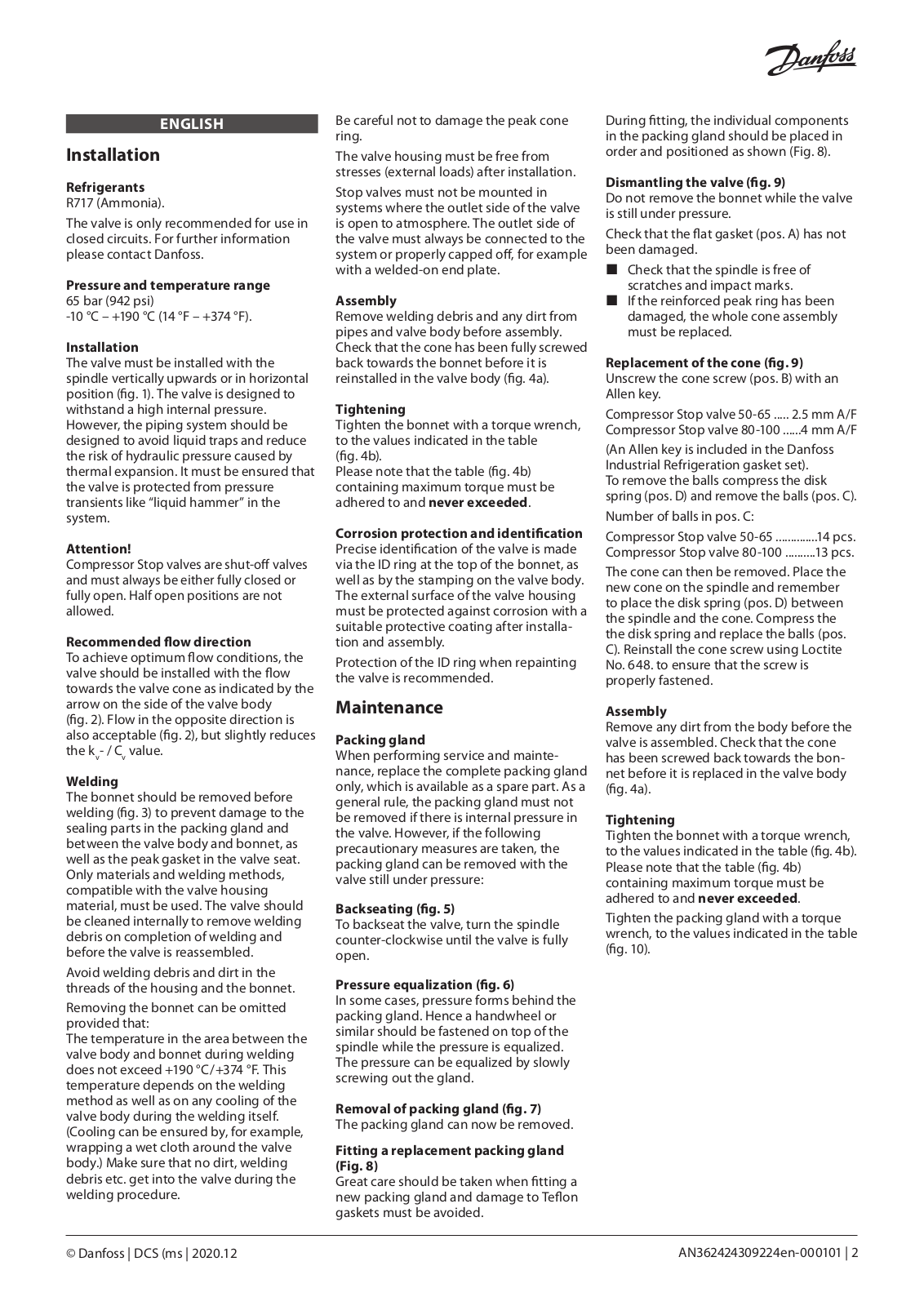
Shut-off valves
Installation guide
2 pgs
390.73 Kb
0
Table of contents
Loading...
Danfoss Shut-off valves Installation guide
...
Danfoss Installation guide
Download
Specifications and Main Features
Frequently Asked Questions
User Manual
Download
Page 1
Page 2
Loading...
+
hidden pages
Unhide
You need points to download manuals.
1 point = 1 manual.
You can buy points or you can get point for every manual you upload.
Buy points
Upload your manuals