

Page 1
Safety Manual
PLUS+1® Safety Controllers
SC0XX-1XX Safety Controller Family
www.danfoss.com
Page 2
Safety Manual
SC0XX-1XX Safety Controller Family
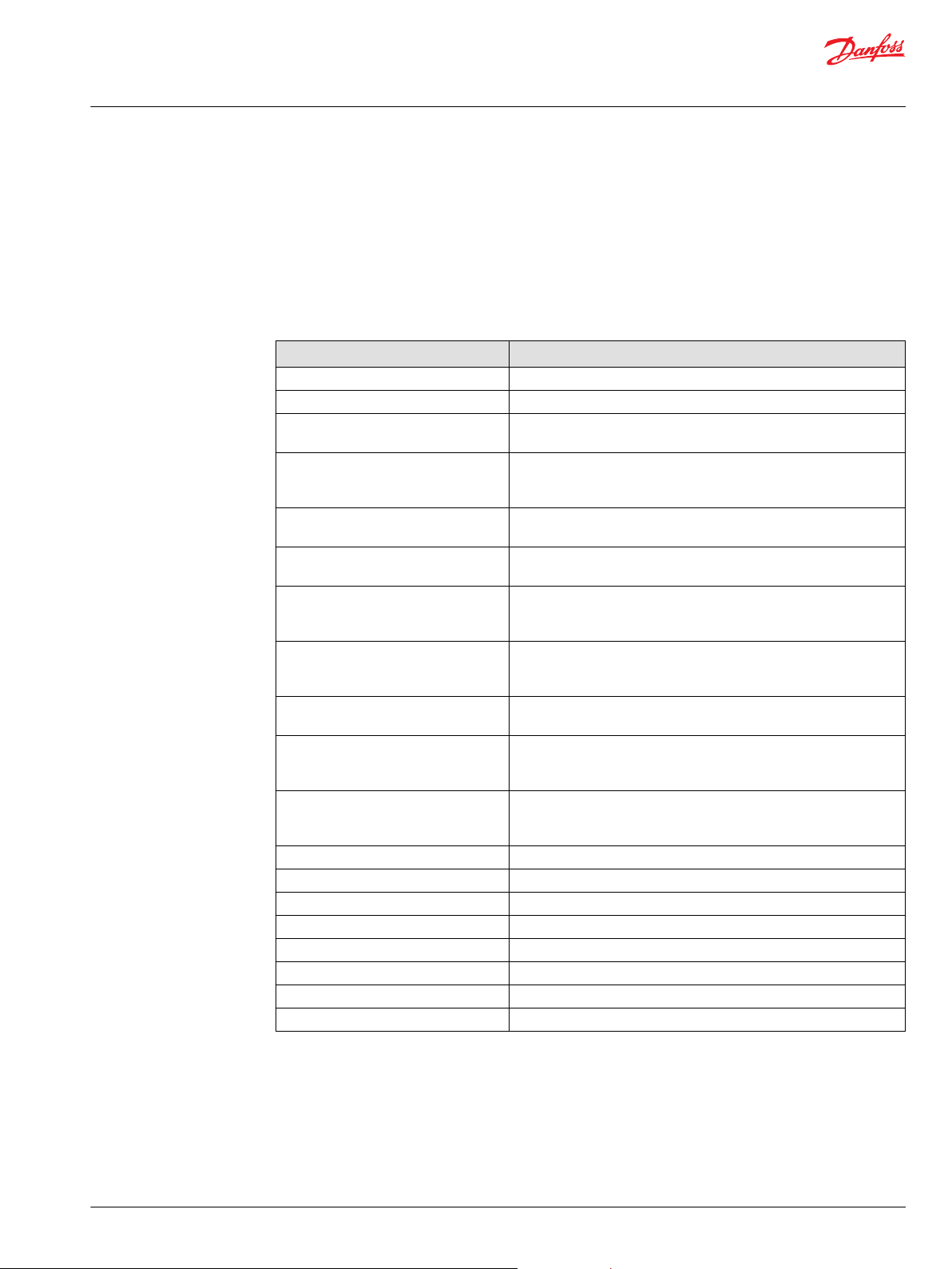
Revision history Table of revisions
Date Changed Rev
December 2020 Corrected table on page 9 0601
June 2019 User application software development requirements, first bullet updated 0501
December 2018 Updated user application software development requirements 0404
August 2018 Corrected typo 0403
August 2018 Corrected title 0402
Changed document number from 'BC00000237' and 'L1420375' to 'BC152986482864' XX
July 2018 Updated IEC 61508 to IEC 61508 : 2010 Parts 1-7 and IEC 62061:2005+ A1:2012+ A2:2015
functional safety standards
April 2017 Recommended diagnostics update; User application software development requirements
update
March 2015 FMEDA analysis; User application software development requirements; and added tables for
control of outputs
December 2014 First edition AA
0401
0301
BA
2 | © Danfoss | December 2020 BC152986482864en-000601
Page 3

Safety Manual
SC0XX-1XX Safety Controller Family
Contents
Introduction
This safety manual............................................................................................................................................................................4
Certified SIL 2 Capable.............................................................................................................................................................. 4
Comprehensive information...................................................................................................................................................4
User information..........................................................................................................................................................................4
Latest version of technical literature....................................................................................................................................5
PLUS+1® SC Controller support................................................................................................................................................... 5
Component description and failure rates
Processors and subsystems.......................................................................................................................................................... 6
FMEDA analysis................................................................................................................................................................................. 6
Failure categories description......................................................................................................................................................7
Failure rates........................................................................................................................................................................................ 8
Recommended diagnostics..........................................................................................................................................................8
Design considerations
Safety critical function.................................................................................................................................................................... 9
Recommended diagnostics.....................................................................................................................................................9
User application software development requirements............................................................................................. 10
Control of DOUT.............................................................................................................................................................................11
Control of PWMOUT/DOUT........................................................................................................................................................12
Environmental limits.....................................................................................................................................................................12
Application limits...........................................................................................................................................................................12
Design verification.........................................................................................................................................................................12
SIL capability....................................................................................................................................................................................12
Systematic capability...............................................................................................................................................................12
Random capability................................................................................................................................................................... 12
Connection to sensors and actuators ....................................................................................................................................13
Requirements.................................................................................................................................................................................. 13
Installation and operation considerations
Installation........................................................................................................................................................................................14
Physical location and placement ............................................................................................................................................ 14
Repair and replacement ............................................................................................................................................................. 14
Useful life...........................................................................................................................................................................................14
Software/hardware version numbers.....................................................................................................................................14
Security considerations................................................................................................................................................................14
Danfoss Power Solutions notification ................................................................................................................................... 14
Using the FMEDA results
PFH calculation or PFD
Example application, failure rate analysis........................................................................................................................15
Abbreviations and definitions
Abbreviations..................................................................................................................................................................................16
Definitions........................................................................................................................................................................................ 16
Appendix A
Risk reduction..................................................................................................................................................................................18
Prerequisites.................................................................................................................................................................................... 19
Requirements for Support Tools and Programming Languages..................................................................................19
Software Safety Validation..........................................................................................................................................................21
calculation................................................................................................................................... 15
AVG
©
Danfoss | December 2020 BC152986482864en-000601 | 3
Page 4
W
Safety Manual
SC0XX-1XX Safety Controller Family
Introduction
This safety manual
This safety manual provides information necessary to design, implement, verify and maintain a safety
critical function utilizing the PLUS+1® SC0XX-1XX Controller Family. This manual provides necessary
requirements for meeting the IEC 61508 : 2010 Parts 1-7 and IEC 62061:2005+ A1:2012+ A2:2015
functional safety standards:
Warning
Read manual completely before programming your application.
Certified SIL 2 Capable
The SC0XX-1XX Controller Family is certified SIL 2 Capable when deployed with the certified SIL 2
Capable OS that is embedded in their respective SC0XX-1XX HWD files.
The SC0XX-0XX Controller Family is designed for meeting the needs of SIL 2 applications where the OEM
certifies at the machine level. The SC0XX-0XX Controller Family is not certified SIL 2 Capable as a
component regardless of the HWD files with which it is deployed. The table below summarizes this
information (the HWD filenames are representative, but not actual).
In all cases, the OEM/customer is responsible for the safety integrity requirement, implementation, and
validation of their application.
Controller
Family
SC0XX-1XX SC0XX-1XX_HWD_Primary*SC0XX-1XX_HWD_Secondary*Yes Yes
SC0XX-1XX SC0XX-0XX_HWD_Primary SC0XX-0XX_HWD_Secondary No Yes
SC0XX-0XX SC0XX-1XX_HWD_Primary*SC0XX-1XX_HWD_Secondary*No Yes
SC0XX-0XX SC0XX-0XX_HWD_Primary SC0XX-0XX_HWD_Secondary No Yes
*
These HWD files incorporate the certified SIL 2 Capable OS with Safety Diagnostic Functions.
HWD for the Primary
Processor
HWD for the Secondary
Processor
Component-Level
SIL 2 Capable
Machine-Level
SIL 2 Capable
Comprehensive information
Manual
Title Type Identification number
PLUS+1® SC0XX-1XX Controller Family Technical Information BC152986482939
PLUS+1® GUIDE Software User Manual Operation Manual AQ152886483724
How to Install PLUS+1® GUIDE Upgrades Operation Manual AQ152886481488
User information
SC Controller model Document number
Primary processor
reference manual
SC050-120/122 70156324 70156321 AI152986482636
SC024-120/122 70156499 70156500 AI152986482900
SC024-110/112 70156496 70156498 AI152986482941
SC050-13H 70153891 70153903 L1407546
Secondary processor
reference manual
Data Sheet
4 | © Danfoss | December 2020 BC152986482864en-000601
Page 5

Safety Manual
SC0XX-1XX Safety Controller Family
Introduction
Latest version of technical literature
Comprehensive technical literature is online at www.danfoss.com
PLUS+1® SC Controller support
Contact information is online at: http://powersolutions.danfoss.com/products/PLUS-1-GUIDE/PLUS-1-
support-and-training/
©
Danfoss | December 2020 BC152986482864en-000601 | 5
Page 6
Connector
Input
conditioning
Power input
Power return
VLDP
Protection and power supplies
Comparator check
V ref
14 V 3 V 5 V
PWM shut-off [1:8]
DOUT shut-off [1:6]
Shut-off check [1:14]
Clock 2
Clock 1
3 V
Reset
Async COM
PWM current feedback [1:8]
PWM control [1:8]
Inputs [1:24]
CAN1
CAN1
CAN2
Sensor power
External
memory
PWM outputs [1:8]
DOUT [1:6]
DOUT status feedback [1:6]
DOUT control [1:6]
Outputs
Power return
Secondary
processor
Voltage
supervisor 2
Voltage
supervisor 1
Primary
processor
3 V
(supply and reference)
Safety Manual
SC0XX-1XX Safety Controller Family
Component description and failure rates
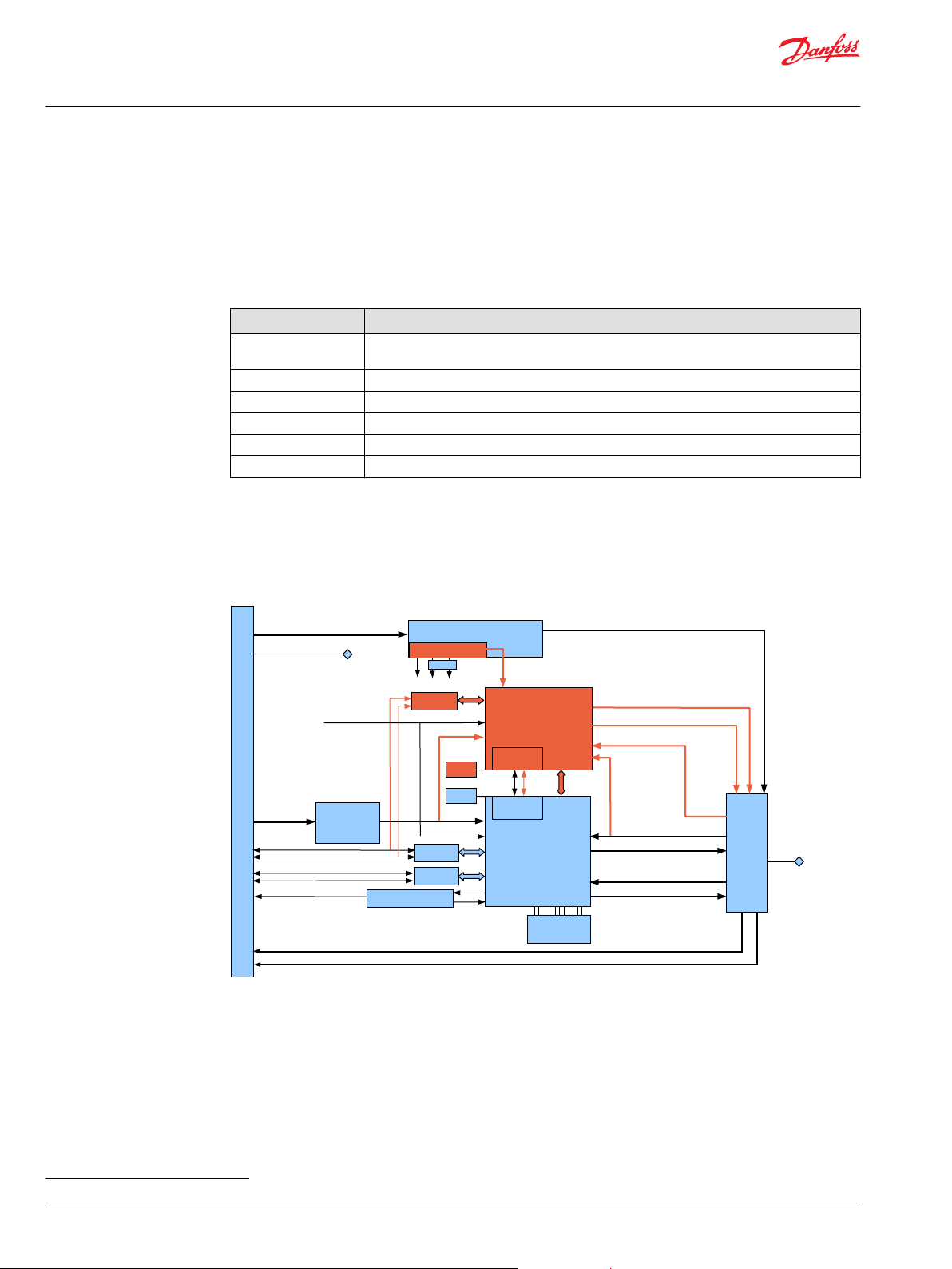
Processors and subsystems
The PLUS+1® SC0XX-1XX Controller has two processors, the primary and the secondary processor, which
communicate asynchronously with each other. The PLUS+1® SC0XX-1XX Controller has six main
subsystems, each of which was analyzed individually. The configuration of a specific controller
deployment is a function of the user application software.
Analyzed subsystems
Subsystem Description
Common Logic Electrical components and circuitry typically involved with all applications regardless of the
DIN/AIN/FreqIN Digital analog and frequency input pins
CrntIn (current) Current input pins
ResIN Resistance input pins
DOUT Digital output pins
CrntOUT (current) Current output pins
FMEDA analysis
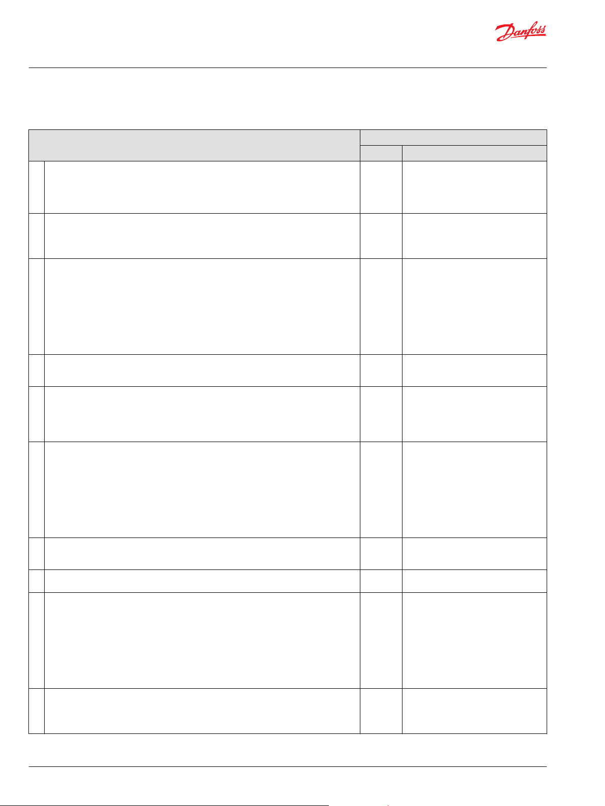
The FMEDA analysis results include the elements shown in the following diagram (components and
inputs/outputs are color coded, blue for the primary processor and red for the secondary processor).
PLUS+1® SC0XX-1XX Controller—Parts included in the FMEDA
input-output channel configuration
6 | © Danfoss | December 2020 BC152986482864en-000601
1
Type B component: “Complex” element (using microcontrollers or programmable logic); for details see 7.4.4.1.3 of IEC 61508.
The PLUS+1® SC0XX-1XX Controller is classified as a Type B1 high demand mode component with HFT = 0
per IEC 61508.
The PLUS+1® SC0XX-1XX Controller is certified to provide a 1oo1D architecture in accordance with IEC
61508. This allows the conclusion that a CAT2 architecture can be implemented in accordance with ISO
13849 or ISO 25119. For example this can be accomplished by using the primary processor as main
controller for the Safety Function and the secondary processor as diagnostic element (intelligent watch
dog, TE-Test Equipment) to observe the correct function of the primary processor and to independently
de-energize (safe-state) all corresponding safety-related outputs.
Page 7
Safety Manual
SC0XX-1XX Safety Controller Family
Component description and failure rates
Detailed analysis, review and documentation for compliance to ISO 13849 or ISO 25119 must be done by
the designer or integrator of the safety related system.
Failure categories description
In order to judge the failure behavior of the PLUS+1® SC0XX-1XX Controller, the following definitions for
the failure of the component apply.
Definitions for failure of the component
Failure category
Fail-Safe State State where the safety output is de-energized.
Fail Safe State where the safety output is de-energized.
Fail Detected Failure that is detected by the PLUS+1® SC Controller and causes the
Fail Dangerous Failure that deviates the measured input state or the actual output by
Fail Dangerous Undetected Failure that is dangerous and that is not being diagnosed by automatic
Fail Dangerous Detected Failure that is dangerous but is detected by automatic diagnostics or is
(2)(3)
Fail High
(2)(3)
Fail Low
No Effect Failure of a component that is part of the safety function but that has no
Annunciation Detected Failure that does not directly impact safety but does impact the ability to
Annunciation Undetected Failure that does not directly impact safety but does impact the ability to
λ
SD
λ
SU
λ
DD
λ
DU
λ
D
A
D
A
U
FIT Failure In Time (1x10⁻⁹ failures per hour)
(1)
The failure categories listed above, expand upon the categories listed in IEC 61508, which are only safe and
dangerous, both detected and undetected. In IEC 61508, the No Effect failures cannot contribute to the failure rate
of the safety function. Therefore, they are not used for the Safe Failure Fraction calculation.
(2)
Depending on the application, a Fail High or a Fail Low failure can either be safe or dangerous and may be
detected or undetected depending on the user software application program.
(3)
Consequently, during a Safety Integrity Level (SIL) verification assessment, the Fail High and Fail Low failure
categories need to be classified as safe or dangerous, and as detected or undetected.
(1)
Definition
output signal to go to the predefined fail safe state.
more than the safety accuracy (2% of span) and that leaves the output
within the active range.
diagnostics or expected user logic.
expected to be detected by user logic.
Failure that causes a safety input signal to go to a value that is clearly
above the normal range and can therefore be reliably detected by the
user application software.
Failure that causes a safety input signal to go to a value that is clearly
below the normal range and can therefore be reliably detected by the
user application software.
effect on the safety function.
detect a future fault (such as a fault in a diagnostic circuit) and that is
detected by internal diagnostics.
detect a future fault (such as a fault in a diagnostic circuit) that is not
detected by internal diagnostics.
Failure rate of all safe detected failures
Failure rate of all safe undetected failures
Failure rate of all dangerous detected failures
Failure rate of all dangerous undetected failures
Failure rate of all dangerous failures, detected and undetected
Failure rate of all annunciation detected failures
Failure rate of all annunciation undetected failures
©
Danfoss | December 2020 BC152986482864en-000601 | 7
Page 8

Safety Manual
SC0XX-1XX Safety Controller Family
Component description and failure rates
Failure rates
FMEDA analysis - Failure rates (FIT)
Controller
Subsystem
Common Logic 2451
DIN/AIN/FreqIN 0 11 0 22
CrntIn (current) 0 5 0 5
ResIN 0 11 0 11
DOUT 73 38 28 1
CrntOUT (current) 143 1 36 10
Recommended diagnostics
The PLUS+1® SC0XX-1XX Controller can be implemented with diagnostics to detect many dangerous
failures and other failures that would result in the controller operating in a degraded mode. The machine
integrator is responsible for the safety and compliance to relevant standards. See Safety critical function
on page 9 for design considerations and diagnostic recommendations.
λ
SD
λ
16
SU
λ
DD
2556 263
λ
DU
8 | © Danfoss | December 2020 BC152986482864en-000601
Page 9

W
Safety Manual
SC0XX-1XX Safety Controller Family
Design considerations
Safety critical function
The PLUS+1® SC0XX-1XX Controller can perform a wide variety of control functions. If these control
functions of the primary processor are safety critical, then additional safety reliability can be achieved by
configuring the secondary processor to monitor the sensor inputs, perform diagnostics, and act to bring
the machine to a safe state if safe operating parameters are violated. The recommended configuration is
to use the secondary processor to monitor the control function of the primary processor.
Recommended diagnostics
The following table lists recommended diagnostics. These diagnostics are implemented in the user
application software that would be loaded into the PLUS+1® SC0XX-1XX Controller.
Warning
If these diagnostics are not implemented, then all dangerous failures should be treated as dangerous
undetected failures.
Diagnostics
Function Failure mode Condition Action Continuous or Start-up
Sensor power Short to battery Analog reading at or near
maximum
Sensor power Short to ground Analog reading at or near
zero
Sensor power Out of range Analog reading different
than expected
Analog input At Max Analog reading at or near
max
Analog input At zero volts Analog reading at or near
zero
Current driver Load shorted Duty cycle at least 50% less
than expected for known
load
Current driver Load shorted Status signal indicates short
circuit
Current driver Open load Duty cycle at least 50% less
than expected for known
load
Current driver Load shorted The output current decays
too slowly after the output is
disabled
Current driver Incorrect load Coil resistance is greatly
different than expected
Digital output Load shorted Status signal indicates short
circuit or open load
Digital output Open load Status signal indicates short
circuit or open load
Battery Power Dangerously High Battery voltage reading
above 36V
Battery Power Dangerously Low Battery voltage reading
below 7V
Frequency input Open Analog reading is at or near
middle voltage
Frequency input No signal Analog value doesn't change
for longer than the
maximum period
CAN Bus off CAN bus status signal
indicates bus off
Stop reading inputs
powered by sensor power.
Stop reading inputs
powered by sensor power.
Can compensate inputs for
new voltage if possible
Stop using this input Continuous
Stop using this input Continuous
Information only or turn off
output
Turn off output immediately Continuous
Information only or turn off
output
Turn off output immediately Continuous
Do not use that output Continuous
Application dependent Continuous
Application dependent Continuous
Turn off all outputs and
ignore inputs
Turn off all PWM outputs Continuous
Ignore frequency input Continuous
Ignore frequency input Continuous
Turn off outputs that rely on
CAN information
Continuous
Continuous
Continuous
Continuous
Start-up
Continuous
Continuous
©
Danfoss | December 2020 BC152986482864en-000601 | 9
Page 10

W
W
Safety Manual
SC0XX-1XX Safety Controller Family
Design considerations
Diagnostics (continued)
Function Failure mode Condition Action Continuous or Start-up
CAN Time out An expected message hasn't
CAN Failed transition Application requests
Configuration Invalid configuration Status signal indicates input
User application software development requirements
Warning
The application programmer must apply these software development requirements when developing
their safety-related system to insure the most robust safety integrity of the system architecture.
Warning
The system must be designed with de-energized as the safe state to assure system safety function.
The CAN bus must not be used for safety critical functions unless a sufficient safety protocol like SAE
•
J1939-76 or EN 50325-5 (CANopen Safety) is deployed for CAN bus communication.
All changes made to the configuration through the service tool must be verified by the user to ensure
•
that they function as expected in the safety controller.
Appropriate action must be taken to put the system into a safe state when an output to output-
•
feedback mismatch error is identified by the application.
The user application software must include plausibility checks on frequency input data to detect
•
possible failures in frequency input calculations.
EEPROM data must include software part number and the user application software should check
•
that this matches with the application.
The user application software must include plausibility checks on all safety relevant inputs.
•
If data is shared between the primary and secondary processors through the internal UART, time
•
monitoring must be used to ensure that messages are being sent within the expected time period.
The user application software must take appropriate action to put the system into a safe state when a
•
current feedback reading mismatch is reported.
If the user application allows it, the current output must periodically be set to zero to allow the zero
•
offset to be recalculated.
For optimal performance, the output current should be set to zero after large temperature changes (>
•
25° C (77° F)) to allow the zero offset to be re-calculated
If the checksum on the EEPROM fails, the user application software must shutdown outputs (de-
•
energize) depending on the EEPROM data or use default data if that can be done safely.
Redundant channels must be utilized to provide reliability where there is concern about channel
•
reliability based on PFH.
Signal comparisons must be implemented by the user application software to compare signals
•
between primary and secondary processors for safety related signals. Function blocks from the Safety
Library can help with this task.
Wiring of the control must be done in compliance with the Danfoss wiring guidelines addressed in
•
PLUS+1® SC0XX-1XX Controller Family Technical Information, BC152986482939.
The user application software must implement strategies to mitigate against the effects of corrupted
•
RAM. For example, include shadow copies of safety critical data and checksums of data.
Internal UART communication implemented by user application software must have as a minimum
•
control mechanism of a heartbeat with sequence signal.
In all cases, the sensor power supply must be monitored and taken into a ratiometric calculation for
•
the analog inputs.
been received in the
expected time
message transmission while
pending flag is active
or output is configured in an
invalid way.
Turn off outputs that rely on
that message
Application dependent Continuous
Make change to application
software
Continuous
Start-up
10 | © Danfoss | December 2020 BC152986482864en-000601
Page 11

Safety Manual
SC0XX-1XX Safety Controller Family
Design considerations
The user application software must implement shutdown of safety critical outputs either by the
•
primary or the secondary processor or by both processors based on user application software safety
requirements.
The user application software must be tested for proper function including fault insertion testing. For
•
more details, see Appendix A on page 18.
The user application software must be tested for proper response to:
•
Highest frequency input conditions.
‒
Highest frequency output conditions.
‒
Highest CAN traffic load conditions on the corresponding used CAN buses.
‒
The user application software must verify that the process time set by function OSExecTimeout
•
(GUIDE API) or by PC_OS_SET_ExecTimeOut (C Open API) can meet the process safety time.
The checksum failure treatment can be set with function OS.ChecksumFailureTreatment (GUIDE API)
•
or by PC_OS_SET_ChecksumFailureTreatment (C Open API) allowing the user application software to
override memory corruption faults and to continue operation instead of turning off all outputs. The
user application software must not override faults, since doing so could result in an unsafe condition.
The user application software must verify that either the primary or the secondary processors or both
•
processors are capable of disabling the safety related outputs.
The user application software must use the frequency values and the count value of the Quad
•
encoder inputs to validate functionality.
The user application software must verify that the current output overload status returns to zero after
•
commanding zero current output.
A Functional Safety Assessment must be conducted before designing any safety related system using
•
the PLUS+1® SC0XX-1XX Controller.
When a high-inductance valve is switched off, false alarms may occur inside the safety layer because
•
the decay of the PWM output current is too slow. This safety monitoring of PWM outputs can be
disabled to improve compatibility with high-inductance valves. This is done by setting
DisableCurrent-DecayRateMonitoring whereby it now becomes the responsibility of the application
to monitor the output current for unintended short (overcurrent) conditions. When such a condition
is detected, the application must immediately disable (turn off) the output. By default,
DisableCurrent-DecayRateMonitoring is not set and the monitoring is done by the kernel.
When a high-inductance valve is switched off, false alarms may occur inside the safety layer because
•
the decay of the digital output current is too slow. This safety monitoring of digital outputs can be
disabled to improve compatibility with high-inductance valves. This is done by setting
DisableOutputSafetyMonitoring whereby it now becomes the responsibility of the application to
monitor the output current for unintended short (overcurrent) conditions. When such a condition is
detected, the application must immediately disable (turn off) the output. By default,
DisableOutputSafetyMonitoring is not set and the monitoring is done by the kernel.
Control of DOUT
DOUT Status Description Recovery
BIT 3 Over temperature/open load
BIT 6 Safety layer failure
BIT 7 Safety FET disabled by secondary
BIT 8 Hardware supply power out of range
©
Danfoss | December 2020 BC152986482864en-000601 | 11
1. The primary application must first command the output to the off-state.
2. The BTS chip temperature must return to its valid range.
3. The kernel then clears status bit 3.
1. The controller must be reset by performing a power cycle.
1. The Safety FET must be off for 250 ms.
2. The primary application must command the output to the off-state.
3. The secondary application can then re-enable the output.
1. The primary application must command ALL outputs to the off-state.
2. The supply voltage must return to its valid range.
3. The kernel then clears status bit 8.
Page 12

Safety Manual
SC0XX-1XX Safety Controller Family
Design considerations
Control of PWMOUT/DOUT
PWMOUT/DOUT
Status
BIT 4 Overload
BIT 5 Incorrect selected output mode
BIT 6 Safety layer failure
BIT 7 Safety FET disabled by secondary
BIT 8 Hardware supply power out of range
Description Recovery
Environmental limits
The designer or integrator of a safety critical function must verify that the safety controller is rated for use
within the expected environmental limits of the target application. Refer to User information on page 4,
for environmental limits.
Application limits
The designer or integrator of a safety critical function must check that the safety controller is rated for use
within the expected application limits. Refer to the PLUS+1® SC0XX-1XX Controller Technical Information,
BC152986482939, for safety controller limits.
1. The kernel will automatically disable the output.
2. The primary application must set the output to the off-state for a
minimum of 250 ms.
3. The kernel then clears status bit 4 and re-enables the output.
1. The primary application must select a valid output mode.
2. The kernel then clears status bit 5.
1. The controller must be reset by performing a power cycle.
1. The Safety FET must be off for 250 ms.
2. The primary application must command the output to the off-state.
3. The secondary application can then re-enable the output.
1. The primary application must command ALL outputs to the off-state.
2. The supply voltage must return to its valid range.
3. The kernel then clears status bit 8.
Design verification
Refer to Failure rates on page 8 for a summary of failure rates for the PLUS+1® SC0XX-1XX Controller.
The achieved Safety Integrity Level (SIL) of an entire Safety Critical Function design must be verified by
the designer or integrator via a calculation of PFH considering the I/O required, demand mode, any
implemented diagnostics, safety time, and architecture.
The failure rate data listed the FMEDA report is only valid for the useful lifetime of a PLUS+1® SC0XX-1XX
Controller. The failure rates will increase sometime after this useful lifetime period. Reliability calculations
based on the data listed in the FMEDA report for mission times beyond the lifetime may yield results that
are too optimistic, in other words, the calculated Safety Integrity Level will not be achieved.
SIL capability
Systematic capability
The systematic capability of the PLUS+1® SC0XX-1XX Controller Family is SC 2 per IEC 61508.
Random capability
Refer to Failure rates on page 8 for a summary of failure rates for the PLUS+1® SC0XX-1XX Controller
Family.
For each user application, the failure rates for the particular configuration should be determined and
compared to the allowable failure rate for a given SIL target.
12 | © Danfoss | December 2020 BC152986482864en-000601
Page 13

Safety Manual
SC0XX-1XX Safety Controller Family
Design considerations
Connection to sensors and actuators
The connection of the PLUS+1® SC0XX-1XX Controller to the required sensors and actuators must be
performed in accordance with the PLUS+1® SC0XX-1XX Controller Family Technical Information,
BC152986482939.
Requirements
The system’s response time must be less than the process safety time defined by the user application.
•
The worst-case response time for a change of value of an analog input or contact signal (measured at
•
the terminals) through the complete system to the completion of change of state of the analog
output or contact output (measured at the terminals) will be a maximum of 10 ms plus the user
application software programmed ExecTimeOut, as measured to the standard outputs. This worst
case time must be determined for the worst-case loading of the safety controller. See User information
on page 4.
The diagnostic self-checks other than the RAM diagnostic self-test and CRC on Flash application must
•
be performed based on demand every loop time, the delay time from the onset of a failure to the
time at which the outputs reach the safe state will be a maximum of 10 ms plus the user application
software program parameter, ExecTimeOut.
The time interval of RAM diagnostic self-check for the platform is a maximum of 1 hour. The time
•
interval RAM test is reported to the user application software.
The CRC flash check time for the user application software is a maximum of 1 hour and is reported to
•
the user application software.
Diagnostics and response times
Description Worst case time Additional information
Diagnostics and Response Times 1 hour Depends on total size of RAM
Flash CRC error detect from onset to
safe state
Change of input to output 10 ms Not including ExecTimeOut
Diagnostic error detection time
from onset to safe state
The maximum delay time from the onset of a failure to the time at which the outputs reach the safe
•
state is the diagnostic time interval plus 10 ms.
All safety related system components, including the PLUS+1® SC Controller, must be operational
•
before machine operation.
Personnel must verify that the PLUS+1® SC Controller is suitable for use in safety applications by
•
confirming the PLUS+1® SC Controller’s nameplate is properly marked.
Personnel performing testing on the PLUS+1® SC Controller must be competent to perform such
•
testing. Functional Safety Training is provided by Danfoss Power Solutions, and details can be found
on the Danfoss Power Solutions website at: http://powersolutions.danfoss.com/solutions/Functional-
safety/.
Results from the functional tests and diagnostics must be recorded and reviewed periodically.
•
1 hour Depends on total size of Flash memory
10 ms Diagnostics are based on demand during execution
loop
©
Danfoss | December 2020 BC152986482864en-000601 | 13
Page 14

Safety Manual
SC0XX-1XX Safety Controller Family
Installation and operation considerations
Installation
The PLUS+1® SC Controller must be installed per standard practices outlined in the PLUS+1® SC0XX-1XX
Controller Family Technical Information, BC152986482939. The environment must be checked to verify
that environmental conditions do not exceed the ratings. Instructions on installation of latest version of
the safety controller HWD file are found in How to Install PLUS+1® GUIDE Upgrades Operation Manual,
AQ152886481488.
Physical location and placement
The PLUS+1® SC Controller must be mounted in accordance with the PLUS+1® SC0XX-1XX Controller Family
Technical Information, BC152986482939, in a low vibration environment. If excessive vibration is
expected, special precautions must be taken to ensure the integrity of electrical connections or the
vibration should be reduced using appropriate damping mounts.
Repair and replacement
The PLUS+1® SC0XX-1XX Controllers are not repairable and no maintenance of them is required.
Useful life
The useful life of the PLUS+1® SC0XX-1XX Controller is 30 years. No proof tests are required.
Software/hardware version numbers
See document for the relevant PLUS+1® SC0XX-1XX Controller, listed under User information on page 4.
Security considerations
The PLUS+1® SC Controller does not use data that the user can configure externally, for example, by the
PLUS+1 Service Tool. The user application software may contain data that is configured externally. If this
is the case, then suitable security should be provided. The PLUS+1® GUIDE Software User Manual,
AQ152886483724 provides a description of how to handle parameters in a safe way.
Danfoss Power Solutions notification
Any failures that are detected and that compromise functional safety should be immediately reported to
Danfoss Power Solutions. Any change suggestions for future improvements or new features can be
forwarded to Danfoss Power Solutions:
Contact information is online at: http://powersolutions.danfoss.com/products/PLUS-1-GUIDE/PLUS-1-
support-and-training/
14 | © Danfoss | December 2020 BC152986482864en-000601
Page 15

Safety Manual
SC0XX-1XX Safety Controller Family
Using the FMEDA results
PFH calculation or PFD
calculation
AVG
An average Probability of Failure per Hour (PFH) or an average Probability of Failure on Demand (PFD
depending on the operating mode, must be determined for each Safety Critical Function. The total will
include the failure rate of all sensors and actuators that are required to perform the function as well as the
elements of the PLUS+1® SC0XX-1XX Controller that are utilized.
Since the elements of the controller subsystem vary based on the Safety Critical Function implemented,
the contribution for the PLUS+1® SC0XX-1XX Controller needs to be determined for each application.
To demonstrate how to calculate the contribution of the PLUS+1® SC0XX-1XX Controller Family, consider
the example of a steering function that is safety critical. The steering function relies on a Steer Command
that is transmitted by a joystick utilizing a single ResIN – Resistance Mode Input. The controller processes
the input and controls the movement of the machine through a dual path control subsystem utilizing
four CrntOUT outputs.
This safety critical function would have an overall failure rate that is the sum of controller subsystems
used which are:
•
(1) Common Logic
•
(1) ResIN
•
(4) CrntOUT (current)
In a machine application, the safety critical function could be operating in high demand. In a high
demand function, only the dangerous undetected failures are included when calculating the PFH. To be
considered a high demand application, the diagnostics must be executed 10 times faster than the
process safety time. Care must be taken when modeling a function as high demand. It is recommended
that the designer or integrator review the requirements with Danfoss Power Solutions to help avoid
understating PFH.
AVG
),
Example application, failure rate analysis
The following table is for an example application. Consider for this example, the function is a high
demand system.
Failure rate analysis for the example function
Controller Subsystem Quantity λ
Common Logic 1 2451 16 2556 263 2819
DIN/AIN/FreqIN 0 0 11 0 22 22
CrntIn (current) 0 0 5 0 5 5
ResIN 1 0 11 0 11 11
DOUT 0 73 38 28 1 29
CrntOUT (current) 4 143 1 36 10 46
Example Total (Sum of
Quantity multiplied by
Column Value)
SD
3023 31 2700 314 3014
λ
SU
λ
DD
λ
DU
Total λ
D
The implementation of the recommended diagnostics (Section 3.1) affects the system failure rate. For
example, if all recommended diagnostics are implemented, only the undetected failures (λDU) contribute
to the failure rate, which is 314 FITS or 3.14x10⁻⁷ failures per hour. This results in a SFF of 94.8%, which is a
SIL2 compliant system.
If none of the recommended diagnostics are implemented, then all failures (λSD, λDU, λDD) are treated as
undetected failures. In this example, the failure rate would then be 3014 FITs or 3.014x10⁻⁶ failures per
hour, which does not meet the SIL2 requirement, but does meet the SIL1 requirements.
©
Danfoss | December 2020 BC152986482864en-000601 | 15
Page 16

Safety Manual
SC0XX-1XX Safety Controller Family
Abbreviations and definitions
Abbreviations
Abbreviations
Abbreviation Definition
EUC Equipment under control.
FMEDA Failure modes, effects and diagnostic analysis.
HFT Hardware fault tolerance.
PFH Probability of failure per hour.
PFD
AVG
SFF Safe failure fraction, summarizes the fraction of failures which lead to a safe state and
SIF Safety instrumented function.
SIL Safety integrity level.
SRS Safety related system, implementation of one or more safety critical functions. An SRS
DIN/AIN/FreqIN Digital analog and frequency input pins.
CrntIn (current) Current input pins.
ResIN Resistance input pins.
DOUT Digital output pins.
CrntOUT (current) Current output pins.
OS Operating system.
Average probability of failure on demand.
the fraction of failures which will be detected by diagnostic measures and lead to a
defined safety action.
is composed of any combination of sensor(s), control module(s), and actuator(s).
Definitions
Definitions
Term Definition
Continuous Demand Mode Mode where the safety function retains the equipment under control in a safe state as
part of its normal operation.
High Demand Mode Mode where the safety function is only performed on demand, in order to transfer the
EUC into a specified safe state, and where the frequency of demands is greater than
one per year.
Low Demand Mode Mode where the safety function is only performed on demand, in order to transfer the
EUC into a specified safe state, and where the frequency of demands is not greater
than one per year. NOTE: The E/E/PE safety-related system that performs the safety
function normally has no influence on the EUC or EUC control system until a demand
arises. However, if the E/E/PE safety-related system fails in such a way that it is unable
to carry out the safety function, then it may cause the EUC to move to a safe state (see
7.4.6 of IEC 61508).
Safety Freedom from unacceptable risk of harm.
Functional Safety The ability of a system to carry out the actions necessary to achieve or to maintain a
defined safe state for the equipment, machinery, plant, and apparatus under control of
the system.
Basic Safety The equipment must be designed and manufactured such that it protects against risk
of damage to persons by electrical shock and other hazards and against resulting fire
and explosion. The protection must be effective under all conditions of the nominal
operation and under single fault conditions.
Safety Assessment The investigation to arrive at a judgment, based on evidence of the safety achieved by
safety-related systems.
Safety Critical Function A set of equipment intended to reduce the risk due to a specific hazard.
Process Safety Time The period of time between a failure occurring in the control system (with the potential
to give rise to a hazardous event) and the occurrence of the hazardous event if the
safety function is not performed.
Type A Component Non-Complex element (using discrete elements); for details see 7.4.4.1.2 of IEC 61508.
16 | © Danfoss | December 2020 BC152986482864en-000601
Page 17

Safety Manual
SC0XX-1XX Safety Controller Family
Abbreviations and definitions
Definitions (continued)
Term Definition
Type B Component Complex element (using micro controllers or programmable logic); for details see
Common Logic Electrical components and circuitry typically involved with all applications regardless of
7.4.4.1.3 of IEC 61508.
the input-output channel configuration.
©
Danfoss | December 2020 BC152986482864en-000601 | 17
Page 18

W
Safety Manual
SC0XX-1XX Safety Controller Family
Appendix A
The following topics are details as they appear in the PLUS+1® GUIDE User Manual, AQ152886483724
regarding risk reduction, software safety validation, and testing the application for proper function
including fault insertion testing. These same precautions must be taken when using PLUS+1® C Open.
Risk reduction
It is important to design, test and secure applications developed with the PLUS+1® GUIDE software to
reduce the risk of personal injury and equipment damage.
The applications that you create with the PLUS+1® GUIDE software typically control heavy, powerful, and
mobile off-road equipment such as tractors, cranes, and harvesters. Under normal operating conditions,
using this type of machinery always involves the risk of personal injury and equipment damage.
Abnormal operating conditions greatly increase the risk of personal injury and equipment damage.
The PLUS+1® GUIDE software has no automatic protections against these risks. The tool has no protection
against the risks that result from bugs in the tool software, errors in the tool manual, or incompatibilities
between software versions of the tool.
Warning
You must design and test your application to reduce these risks. Secure your application against
unauthorized changes in its operating parameters to reduce these risks.
Design
You have the responsibility when you design a PLUS+1® GUIDE application to include the fault checking
and the error handling needed to reduce risks in normal and abnormal operating conditions. The
following are some items to consider when developing fault checking and error handling for your
application:
•
How the machine is normally used.
•
Possible operator errors and their consequences.
•
Industry safety standards and legal requirements.
•
Input and output failures and their consequences. These failures can include:
Joystick, sensor, and other inputs suddenly going to ±100 % or to 0 %.
‒
Outputs that control machinery direction, speed, and force suddenly changing direction or going
‒
to ±100 % or to 0 %. Decide how likely each failure is. The more likely a failure, the more you need
to protect against the consequences of the failure.
•
The sequence of events and consequences of a fault or error.
•
The sequence of events and consequences of an emergency stop.
Test
You have the responsibility once you have created an application to test the application. You should
download your application to hardware and test its operation under both normal and abnormal
operating conditions. You should make sure that:
•
Individual inputs produce expected outputs.
•
Fault handling and error checking work as designed.
You must repeat your tests whenever you make configuration, calibration, or software changes to your
application.
Secure
•
You have the responsibility to secure your application against unauthorized changes.
•
You should always use the PLUS+1® GUIDE program’s Tool Key feature (or a parameter PIN feature for
PLUS+1® C Open) to restrict access to your application’s operating parameters.
18 | © Danfoss | December 2020 BC152986482864en-000601
Page 19

W
Safety Manual
SC0XX-1XX Safety Controller Family
Appendix A
Without Tool Key or PIN protection, there is an increased risk that unauthorized personnel could
‒
use the PLUS+1® Service Tool program to change your application’s operating parameters
Tool Key/PIN protection reduces the risk that unauthorized personnel could use the PLUS+1
‒
Service Tool program to change your application’s operating parameters.
Warning
Changes in your application’s operating parameters could cause unexpected machinery movement that
result in personnel injury and equipment damage.
Prerequisites
The Statements: Yes, No, Partial in the table below appear in the Fulfill columns in the tables on the
following pages.
The statements in this table are only from a PLUS+1® tool perspective.
The overall responsible person for checking the fulfillment of the requirement in IEC 61508 and ISO
13849-1 must investigate which additional measures that needs to be taken for each individual
requirement before it is completely fulfilled.
®
Statement Description
Yes
Yes*
No
Partially
Partially*
N/A
This requirement is automatically fulfilled by using PLUS+1® tools.
Full conformance with this requirement demands that the software application designer
considers the measures described in the column “detailed description.”
This requirement is not fulfilled by using PLUS+1® tools.
Indicate that the PLUS+1® tools do not cover all the requirements in an Annex B table that is
referenced from a certain technique and measure described in an Annex A table, or only covers
certain of the requirements within the sub chapter.
The additional measures, beyond those described in the column “Detailed description,” that has
to be performed for claiming full conformance with this requirement will vary from case to case.
The application designer will be responsible for this work.
Not applicable for support tools.
Requirements for Support Tools and Programming Languages
7.4.4—Requirements for Support Tools and Programming Languages
PLUS+1 GUIDE Tools
Subclause
1. A software on-line support tool shall be considered to be a software element of the safety
related system.
2. Software off-line support tools shall be selected as a coherent part of the software
development activities.
3. The selection of the off-line support tools shall be justified. Yes PLUS+1® GUIDE and PLUS+1® Service
4. All off-line support tools in classes T2 and T3 shall have a specification or product
documentation which clearly defines the behavior of the tool and any instructions or
constraints on its use. See 7.1.2 for software development lifecycle requirements, and 3.2.11
of IEC 61508-4 for categories of software off-line support tool.
1)
Fulfill
N/A Not applicable since PLUS+1® GUIDE and
Yes Selecting tools is covered by using PLUS
Yes PLUS+1® GUIDE and PLUS+1® Service
Detailed description
PLUS+1® Service Tool are certified as offline support tools. Documented by the
certificate.
+1® GUIDE and PLUS+1® Service Tool.
Tool are certified as off-line support tools
in accordance to IEC61508.
Tool User Manuals defines the behavior
of the tools.
Fully covered and documented by the
certificate
.
©
Danfoss | December 2020 BC152986482864en-000601 | 19
Page 20
Safety Manual
SC0XX-1XX Safety Controller Family
Appendix A
7.4.4—Requirements for Support Tools and Programming Languages (continued)
Subclause
5.
An assessment shall be carried out for offline support tools in classes T2 and T3 to
determine the level of reliance placed on the tools, and the potential failure mechanisms of
the tools that may affect the executable software. Where such failure mechanisms are
identified, appropriate mitigation measures shall be taken.
6.
For each tool in class T3, evidence shall be available that the tool conforms to its
specification or documentation. Evidence may be based on a suitable combination of
history of successful use in similar environments and for similar applications (within the
organization or other organizations), and of tool validation as specified in 7.4.4.7.
7.
The results of tool validation shall be documented covering the following results:
A) A chronological record of the validation activities;
B) The version of the tool product manual being used;
C) The tool functions being validated;
D) Tools and equipment used;
E) The results of the validation activity; the documented results of validation shall state
either that the software has passed the validation or the reasons for its failure;
F) Test cases and their results for subsequent analysis;
G) Discrepancies between expected and actual results.
8. Where the conformance evidence of 7.4.4.6 is unavailable, there shall be effective measures
to control failures of the executable safety related system that result from faults that are
attributable to the tool.
9. The compatibility of the tools of an integrated toolset shall be verified. Yes
10.
To the extent required by the safety integrity level, the software or design representation
(including a programming language) selected shall:
A) Have a translator which has been assessed for fitness for purpose including, where
appropriate, assessment against the international or national standards;
B) Use only defined language features;
C) Match the characteristics of the application;
D) Contain features that facilitate the detection of design or programming mistakes;
E) Support features that match the design method.
11. Where 7.4.4.10 cannot be fully satisfied, the fitness for purpose of the language, and any
additional measures which address any identified shortcomings of the language shall be
justified.
12. Programming languages for the development of all safety-related software shall be used
according to a suitable programming language coding standard.
13.
A programming language coding standard shall specify good programming practice,
proscribe unsafe language features (for example, undefined language features,
unstructured designs, etc.), promote code understandability, facilitate verification and
testing, and specify procedures for source code documentation. Where practicable, the
following information shall be contained in the source code:
A) Legal entity (for example company, author(s), etc.);
B) Description;
C) Inputs and outputs;
D) Configuration management history.
14. Where automatic code generation or similar automatic translation takes place, the
suitability of the automatic translator for safety-related system development shall be
assessed at the point in the development lifecycle where development support tools are
selected.
PLUS+1 GUIDE Tools
1)
Fulfill
Yes PLUS+1® GUIDE and PLUS+1® Service
Yes
Yes
— Not applied since 7.4.4.6 is fulfilled.
N/A
— Not applied since 7.4.4.10 is fulfilled.
Yes* PLUS+1 Development Guidelines.
Yes* PLUS+1 Development Guidelines.
Yes
Detailed description
Tool are certified as off-line support tools
in accordance to IEC61508.
Fully covered and documented by the
certificate.
PLUS+1® GUIDE is certified as off-line
support tool in accordance to IEC61508.
Fully covered and documented by the
certificate.
PLUS+1® GUIDE and PLUS+1® Service
Tool are certified as off-line support tools
in accordance to IEC61508.
Fully covered and documented by the
certificate.
PLUS+1® GUIDE and PLUS+1® Service
Tool are certified as off-line support tools
in accordance to IEC61508.
Fully covered and documented by the
certificate.
PLUS+1® GUIDE is certified as off-line
support tools in accordance to IEC61508
(A).
Dependency view support detection of
design and programming mistakes (D).
PLUS+1® GUIDE provides features to
match the characteristics of control
applications and control flow designs (C
and E).
PLUS+1® GUIDE is certified as off-line
support tool in accordance to IEC61508.
Fully covered and documented by the
certificate.
20 | © Danfoss | December 2020 BC152986482864en-000601
Page 21

Safety Manual
SC0XX-1XX Safety Controller Family
Appendix A
7.4.4—Requirements for Support Tools and Programming Languages (continued)
Subclause
15.
Where off-line support tools of classes T2 and T3 generate items in the configuration
baseline, configuration management shall ensure that information on the tools is recorded
in the configuration baseline. This includes in particular:
A) The identification of the tool and its version;
B) The identification of the configuration baseline items for which the tool version has been
used;
C) The way the tool was used (including the tool parameters, options and scripts selected)
for each configuration baseline item.
16. Configuration management shall ensure that for tools in classes T2 and T3, only qualified
versions are used.
17. Configuration management shall ensure that only tools compatible with each other and
with the safety-related system are used.
18.
Each new version of off-line support tool shall be qualified. This qualification may rely on
evidence provided for an earlier version if sufficient evidence is provided that:
A) The functional differences (if any) will not affect tool compatibility with the rest of the
toolset; and
B) The new version is unlikely to contain significant new, unknown faults.
19.
Depending on the nature of the software development, responsibility for conformance with
7.4.4 can rest with multiple parties. The division of responsibility shall be documented
during safety planning (see Clause 6 of IEC 61508-1).
1)
See the table Prerequisites on page 19 for more information about the items in this column.
PLUS+1 GUIDE Tools
1)
Fulfill
Yes Version control support of the project
Yes For certified hardware there is the
Yes
Yes
Yes* The user of the PLUS+1 GUIDE software
Detailed description
file (P1x) contains the information to
fulfill this clause.
possibility to compile as safety related
software.
That will require qualified PLUS+1
GUIDE and PLUS+1® Service Tool.
For complete Danfoss systems this is
fully covered and documented by the
certificate.
For systems containing non-Danfoss
parts the system integrator needs to
document the compatibility.
PLUS+1® GUIDE and PLUS+1® Service
Tool are certified as off-line support tools
in accordance to IEC61508.
Fully covered and documented by the
certificate.
tool and the software tool itself share the
responsibility for support tools and
programming languages.
(See clauses 7.4.4.1–7.4.4.18.)
®
Software Safety Validation
7.7.2—Software Safety Validation
PLUS+1® tools
Subclause
1. If the compliance with the requirements for safety related software has already been
established in the safety validation planning for the E/E/PE safety-related system (see 7.7 of
IEC 61508-2), then the validation need not be repeated.
2. The validation activities shall be carried out as specified in the validation plan for software
aspects of system safety.
3. Depending on the nature of the software development, responsibility for conformance with
7.7 can rest with multiple parties. The division of responsibility shall be documented during
safety planning (see clause 6 of IEC 61508-1).
4. The results of validating the software aspects of system safety shall be documented. Yes* Test tool feature built in but the software
©
Danfoss | December 2020 BC152986482864en-000601 | 21
1)
Fulfill
N/A ——
N/A ——
Partially The user of the PLUS+1® GUIDE software
Detailed description
tool and the software tool itself share the
responsibility for software design and
development. (See clauses 7.7.2.1–
7.7.2.9.)
application designer has the
responsibility to utilize these features.
Page 22

Safety Manual
SC0XX-1XX Safety Controller Family
Appendix A
7.7.2—Software Safety Validation (continued)
PLUS+1® tools
Subclause
5.
For each safety function, software safety validation shall document the following results:
A) A chronological record of the validation activities that will permit the sequence of
activities to be retraced;
B) The version of the validation plan for software aspects of system safety (see 7.3) being
used;
C) The safety function being validated (by test or analysis), together with reference to the
validation plan for software aspects of system safety;
D) Tools and equipment used together with calibration data;
E) The results of the validation activity;
F) Discrepancies between expected and actual results.
6. When discrepancies occur between expected and actual results, the analysis made and the
decisions taken on whether to continue the validation, or to issue a change request and
return to an earlier part of the development lifecycle, shall be documented as part of the
results of validating the software aspects of system safety.
7.
The validation of safety-related software aspects of system safety shall meet the following
requirements:
A) Testing shall be the main validation method for software; analysis, animation and
modeling may be used to supplement the validation activities;
B) The software shall be exercised by simulation of:
1) Input signals present during normal operation;
2) Anticipated occurrences;
3) Undesired conditions requiring system action.
C) The supplier and/or developer (or the multiple parties responsible for compliance) shall
make available the documented results of the validation of software aspects of system
safety and all pertinent documentation to the system developer to enable his product to
meet the requirements of IEC 61508-1 and IEC 61508-2.
8. Software tools shall meet the requirements of 7.4.4. Yes See 7.4.4. Requirements for Support Tools
9.
The results of the validation of safety-related software aspects of system safety shall meet
the following requirements:
A) The tests shall show that all of the specified requirements for safety-related software (see
7.2) are correctly met and the software does not perform unintended functions;
B) Test cases and their results shall be documented for subsequent analysis and
independent assessment (see clause 8 of IEC 61508-1) as required by the safety integrity
level;
C) The documented results of validating the software aspects of system safety shall state
either (1) That the software has passed the validation or (2) The reasons for not passing the
validation.
1)
See the table Prerequisites on page 19 for more information about the items in this column.
1)
Fulfill
Partially*
N/A ——
Partially*
Yes* Test tool provides sufficient means to
Detailed description
Version control support enables the use
of external configuration/test
management systems (A).
Test tool built in that enables validation
by testing (B–F).
PLUS+1® Service Tool provides sufficient
means to support testing of safetyrelated software (A and B).
Test tool further enhances the ability to
test safety-related software (A and B).
Subsection C is dependent on the
organization where the system is
developed. The tools have no explicit
support for this step.
and Programming Languages on page 19.
support this requirement.
22 | © Danfoss | December 2020 BC152986482864en-000601
Page 23

Danfoss
Power Solutions GmbH & Co. OHG
Krokamp 35
D-24539 Neumünster, Germany
Phone: +49 4321 871 0
Danfoss
Power Solutions ApS
Nordborgvej 81
DK-6430 Nordborg, Denmark
Phone: +45 7488 2222
Danfoss
Power Solutions (US) Company
2800 East 13th Street
Ames, IA 50010, USA
Phone: +1 515 239 6000
Danfoss
Power Solutions Trading
(Shanghai) Co., Ltd.
Building #22, No. 1000 Jin Hai Rd
Jin Qiao, Pudong New District
Shanghai, China 201206
Phone: +86 21 2080 6201
Products we offer:
Hydro-Gear
www.hydro-gear.com
Daikin-Sauer-Danfoss
www.daikin-sauer-danfoss.com
Cartridge valves
•
DCV directional control
•
valves
Electric converters
•
Electric machines
•
Electric motors
•
Gear motors
•
Gear pumps
•
Hydraulic integrated
•
circuits (HICs)
Hydrostatic motors
•
Hydrostatic pumps
•
Orbital motors
•
PLUS+1® controllers
•
PLUS+1® displays
•
PLUS+1® joysticks and
•
pedals
PLUS+1® operator
•
interfaces
PLUS+1® sensors
•
PLUS+1® software
•
PLUS+1® software services,
•
support and training
Position controls and
•
sensors
PVG proportional valves
•
Steering components and
•
systems
Telematics
•
Danfoss Power Solutions is a global manufacturer and supplier of high-quality hydraulic and
electric components. We specialize in providing state-of-the-art technology and solutions
that excel in the harsh operating conditions of the mobile off-highway market as well as the
marine sector. Building on our extensive applications expertise, we work closely with you to
ensure exceptional performance for a broad range of applications. We help you and other
customers around the world speed up system development, reduce costs and bring vehicles
and vessels to market faster.
Danfoss Power Solutions – your strongest partner in mobile hydraulics and mobile
electrification.
Go to www.danfoss.com for further product information.
We offer you expert worldwide support for ensuring the best possible solutions for
outstanding performance. And with an extensive network of Global Service Partners, we also
provide you with comprehensive global service for all of our components.
Local address:
Danfoss can accept no responsibility for possible errors in catalogues, brochures and other printed material. Danfoss reserves the right to alter its products without notice. This also applies to products
already on order provided that such alterations can be made without subsequent changes being necessary in specifications already agreed.
All trademarks in this material are property of the respective companies. Danfoss and the Danfoss logotype are trademarks of Danfoss A/S. All rights reserved.
©
Danfoss | December 2020 BC152986482864en-000601
 Loading...