

Page 1
Data sheet
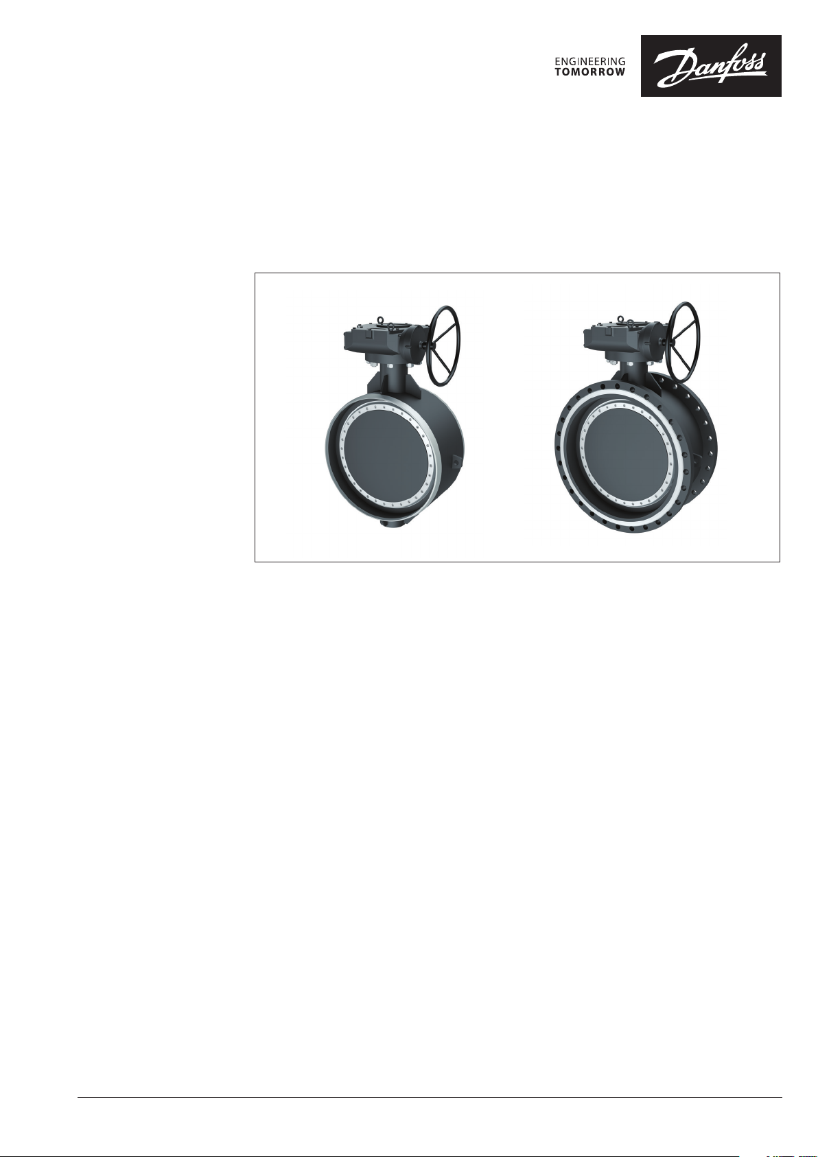
Steel buttery valves
SBFV (PN 16/25)
Description
Danfoss SBFV are high performance steel
butterfly valves that together with Danfoss JIP™
ball valves complete the family of shut off valves
designed especially for district heating and
district cooling systems.
Danfoss SBFV are triple offset butterfly valves
with unique lamelar seat design that ensures
reliable operation and tightness even at high and
low temperatures. They are primarily designed as
shut-off valves but can be as well used for simple
control purposes.
Packing box has been designed on the same
principle as on JIP™ ball valves where carbon
reinforced PTFE sealing is used that does not
deteriorate over years and can be tightened
while in the pipeline thus ensuring external
tightness for lifetime.
Main data:
• DN 200–1400
• Maximum differential pressure 16 bar
• kVS: 1270 - 88000 m3/h
• Leakage rate A
• Body design class PN 25
• Temperature: −20 (−40) … 240°C
• Medium: circulation water/ glycolic water up
to 50%
• Minimum ambient temperature for
transportation and storage: −40°C
Approvals and norms:
• 100% final inspection. Leak and shell test,as
well as dimension and functionality test is
performed on each and every valve according
to applicable standard EN 12266 P10-P11-P12
& F20
• All used material with EN 10204 3.1 certificates
• Production certified according to ISO9001 /
ISO14001
© Danfoss | 2021.08
AI165686469433en-010707 | 1
Page 2
Data sheet Steel buttery valves SBFV (PN 16/25)
Ordering
SBFV-WW welding
SBFV-FF flange
DN
(mm)
200 065B7610 065B7655 065B7625 065 B7670 065B7640 065 B7685
250 065 B7611 065B7656 065B7626 0 65B7671 0 65B76 41 065B76 86
300 065B7 612 065B7657 065B7627 065B7672 065B7642 065B76 87
350 06 5B7613 065B7658 065B7628 065B 7673 065B7643 0 65B7688
400 065 B7614 065B7659 065B7629 06 5B7674 065B7644 06 5B7689
450 06 5B7615 0 65B7660 065B763 0 065B7675 065B7645 06 5B7690
500 065 B7616 0 65B76 61 065 B7631 0 65B7676 06 5B7646 0 65B7691
600 065 B7617 065B7662 065B76 32 065B 7677 065B7647 0 65B7692
700 06 5B7618 065B766 3 065B7633 065B767 8 065B7648 065B76 93
800 065B7619 065B7664 065B7634 065 B7679 065B7649 065B769 4
900 065B7620 065B7665 065B7635 065B7680 065B7650 065B7695
1000 065B7621 065B7666 065B7636 065B76 81 065B7651 065B7696
120 0 065B7622 065B 7667 065 B7637 065B7682 065B7652 065B769 7
140 0 065B7623 065B7668 065B763 8 065B7683 065B7653 065B76 98
200 065H7610 065H7655 065H7625 065H7670 0 65H7640 065 H7685
250 06 5H7 611 065H7656 065H7626 065H7671 0 65H76 41 065H7686
300 065 H7612 0 65H7657 065H7627 065H7672 06 5H7642 0 65H7687
350 065 H7613 065H7658 065H7628 065H7673 065H 7643 065 H7688
400 065H 7614 065H7659 065H7629 06 5H7674 065H7644 065H76 89
450 065 H7615 065H76 60 065H7630 065H7675 065 H7645 06 5H7690
500 065H7616 0 65H7661 0 65H7631 0 65H7676 065H76 46 065 H7691
600 065H7617 065H7662 065H7632 0 65H7677 0 65H7647 065 H7692
700 065 H7618 0 65H7663 065 H7633 06 5H7678 06 5H7648 0 65H7693
800 065H7 619 065H 7664 065H7634 065H7679 0 65H7649 065 H7694
900 065H7620 065H7665 06 5H7635 065H76 80 065H7650 065H7695
1000 065H7621 065H7666 065H763 6 065H76 81 065H7651 065H7696
120 0 065H7622 0 65H7667 065H7637 065H7682 065H7652 065H7697
140 0 065H7623 065 H7668 06 5H7638 065H7683 065H7653 065 H7698
Code Nr. WW PN 25 Code Nr. FF PN 16 Code Nr. FF PN 25
with gearbox 1)with gear flange 1)with gearbox 1)with gear flange 1)with gearbox 1)with gear flange
GOST/CN-B connection
EN connections
1)
1)
All valves are 10 0% factory tes ted for
int ⁄ext leakag e from both directions
Danfoss guara ntees leakage class A
from both dire ctions only with factor y
installed gear boxes and electric
actuators a ccording to the specificati on
in this data sheet
Danfoss can’t acce pt the responsibility
for potential l eakage as a result of the
improper g ear box or electric ac tuator
installation a nd use of gear boxes
and electric actuators which are not
according to the spe cification
2 | © Danfoss | 2021.08
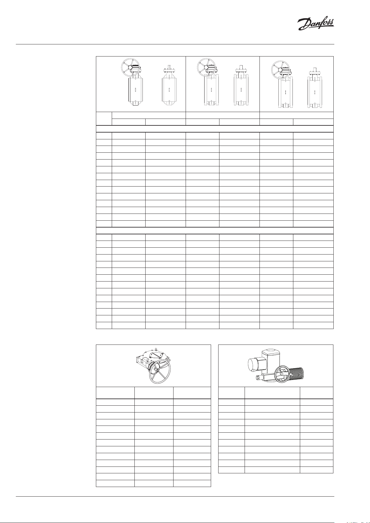
Gear box
DN
(mm)
200 AB550 065B8280
250 AB880 065B8281
300 -350 AB12 50 065B8282
400 AB1950 065B8283
450 AB1950/PR4 065B8284
500 AB3000/PR4 065B8291
600 AB3000/PR6 065B8292
700 AB6800/PR6 065B8285
800 A20 0/PR10 065B8286
900 A250/PR10 065B8287
1000 IW82 065B8288
120 0 IW9 065B8289
140 0 HOW10 065B8290
Gear box t ype Cod e Nr.
Electrical actuator Auma
DN
(mm)
200 S Q12. 2-F12 065B8260
250 SA10.2-GS80.3/53:1-F12 065B8253
300 -350 SA10.2-GS100.3/126:1-F14 065B8 261
400 -450 SA10. 2-GS125 .3/160 :1-F16 065B8262
500 SA10.2-GS125.3/208:1-F25 065B8263
600 SA10.2-GS160.3/442:1-F25 065B8258
700-800 SA10.2-GS200.3/864:1-F30 065B8264
900 SA10.2-GS250.3/848:1-F35 065B8265
1000 SA10.2-GS250.3/1718:1-F35 065B8259
120 0 SA10.2-GS315/1696:1-F40 065B8266
140 0 SA14.2- GS315/1696:1-F40 065B8267
Actuator type Code Nr.
AI165686469433en-010707
Page 3
Data sheet Steel buttery valves SBFV (PN 16/25)
Technical data
DN 200 250 300 350 400 450 500 600 700 800 900 1000 120 0 140 0
k
VS
PN
∆p max. 16
Medium temperature
Min. Ambient temperature −20 (−40 2))
Max. Ambient temperature 80 (with Auma actuator); 110 (with Gearbox); 240 (only valve)
Medium Circulation water/glycolic water up to 50 %
3)
Torque
1)
Temperature depen ds on the pressure. See pressure -temperature diagram f or details.
2)
Product needs pr oper insulation that will e nsure that surface temperatu re of the valve will not be lower th en -20°C when val ve is pressurized
3)
Torque values should b e increased by 10% when dimension ing third party act uators that are not recommen ded by Danfoss
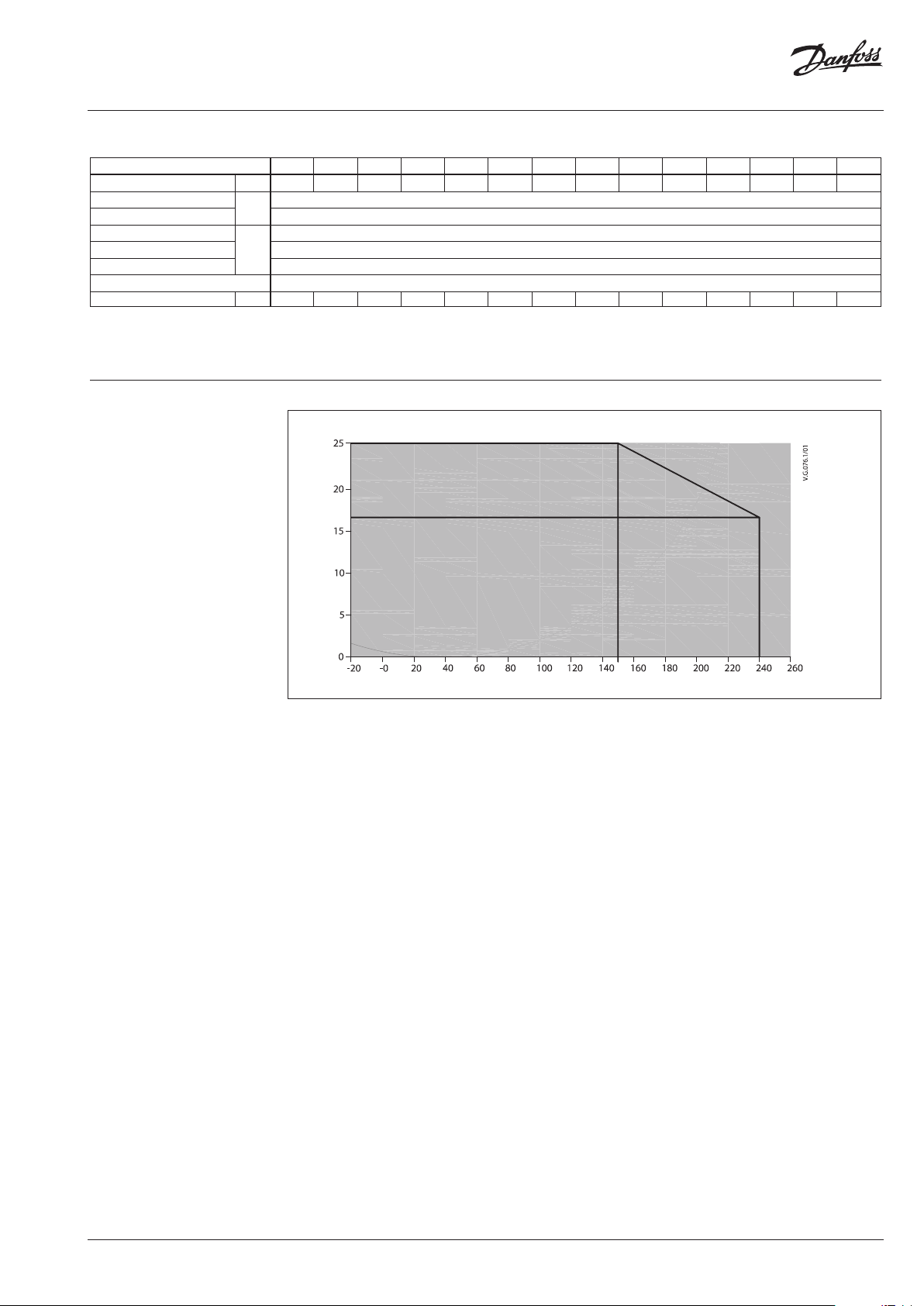
Pressure temperature
diagram (valve body design)
m3/h 1270 2100 3900 5200 6700 8700 11000 15000 23500 28000 40000 52000 65000 88000
bar
16 / 25
−20 … 240
1)
°C
Nm 950 13 00 2500 3100 3950 5250 6600 9400 158 00 20500 28300 36000 58400 82000
PN 25 Work ing pressure/workin g temperature rating
PN 16
Working pressur e [bar]
Working tempe rature [T, °C]
AI165686469433en-010707
© Danfoss | 2021.08 | 3
Page 4

Data sheet Steel buttery valves SBFV (PN 16/25)
DN 1000
DN 1200
DN 1400
100.000
Opening angle [°]
Flow diagram
10.000
/h]
3
[m
v
k
1.000
100
0102030405060708090
DN 900
DN 800
DN 700
DN 600
DN 500
DN 450
DN 400
DN 350
DN 300
DN 250
DN 200
For best performance of controlling the flow
please choose dedicated Danfoss control valves.
SBFV butterfly valves can be used for simple
regulation in opening angles from 30°to 90°.
To avoid high flow speed, cavitation and
turbulence, opening angle from 0-30° should not
be used.
Design
N° Part Material
1 Body
2 Disk
3 Retaining ring Stainless steel X5CrNi18-10
4 Lamellar seal X6CrNiMoTi17-12-2+Graphite
5 Valve seat Stainless steel X17CrNi16-2
6 Drive Shaf t Stainless steel X17CrNi16-2
7 Gland packing Graphite / PTFE
8 Ring Stainless steel X5CrNi18-10
9 Sealing bush GGG CrNi20-2
10 Gland
11 Cover
12 Pin Stainless steel X17CrNi16-2
13 Parallel key Carbon steel C45E
14 Radial bearing INA PERMAGLIDE (SS+PTFE)
15 Axial bearing INA PERMAGLIDE (SS+PTFE)
16 Connections Stainless steel A4-70
17 Connections Stainless steel A4-70
18 Screw Stainless steel A4-70
19 “O” ring EPDM HT / VITON
Carbon steel EN 10028-2 P265GH,
EN 10025 S355J2+N
Carbon steel EN 10028-2 P265GH,
EN 10025 S355J2+N
Carbon steel EN 10028-2 P265GH,
EN10025 S355J2+N
Carbon steel EN 10028-2 P265GH,
EN 10025 S355J2+N
Maximum flow velocities for media should not
exceed:
-3 m/s [DN200-400]
- 2,5 m/s [DN450-800]
- 2 m/s [DN1000-1400]
4 | © Danfoss | 2021.08
AI165686469433en-010707
Page 5

Data sheet Steel buttery valves SBFV (PN 16/25)
Dimensions
SBFV-WW with bare shaft
1
2
D
D
h
1
L
D
H
h
1
1
d
h
2
L
DN
(mm)
L D
GOST end EN end
D1D2D1D
h H h1d1h2L
2
mm
1
Gear
Flange
IS O5211
200 230 14 5 210 219 210 219 170 255 60 32 145 340 F12 38
250 250 205 263 273 263 273 200 290 60 36 155 378 F12 53
300 270 245 311 325 313 324 235 320 73 48 155 450 F14 79
350 290 295 363 377 344 356 265 350 73 48 159 510 F14 10 6
400 310 340 408 426 394 406 305 410 90 48 192 510 F16 14 4
450 330 385 444 457 444 457 315 430 10 0 50 190 610 F16 166
500 350 445 512 530 495 508 370 458 10 5 60 186 665 F25 225
600 390 490 608 630 596 610 420 555 115 72 232 770 F25 333
700 430 590 702 720 695 7 11 485 600 130 90 240 860 F30 500
800 470 690 804 820 795 813 550 650 115 98 235 977 F30 6 81
900 510 785 9 02 920 894 914 590 755 160 110 290 10 87 F35 942
1000 550 870 994 1020 994 1016 655 805 16 0 12 5 290 1176 F35 1243
120 0 630 11 80 1194 1220 119 4 1219 750 905 220 155 290 136 0 F40 1960
140 0 710 1300 1398 1420 1397 1422 860 100 5 225 175 380 1739 F40 2890
Weight
(kg)
SBFV-FF with bare shaft PN16
ØD
ØK
DN
DN
(mm)
L
GOST end EN end
ØD ØK n Øl ØD ØK n Øl
h
1
L
L
H
n × Øl
h H h1d1h2L
mm
h
1
1
d
h
2
Gear
1
Flange
IS O 52 11
200 230 335 295 12 22 340 295 12 22 170 255 60 32 145 340 F12 62
250 250 405 355 12 26 405 355 12 26 200 290 60 36 155 378 F12 73
300 270 460 410 16 26 460 410 12 26 235 320 73 48 155 450 F14 104
350 290 520 470 16 26 520 470 16 26 265 350 73 48 159 510 F14 165
400 310 580 525 16 30 580 525 16 30 305 410 90 48 192 570 F16 235
450 330 640 585 20 30 640 585 20 30 315 430 10 0 50 19 0 610 F16 280
500 350 710 650 20 33 715 650 20 33 370 458 105 60 186 660 F25 366
600 390 840 770 20 39 840 770 20 36 420 555 115 72 232 770 F25 573
700 430 910 840 24 39 910 840 24 36 485 600 130 90 24 0 860 F30 733
800 470
900 510 1120
1000 550
120 0 630
140 0 710
1020
950 24 39
1050
1255
1170 28 45
1485
139 0
1685
1590
1025
28 39 1125
1255
32 52
36 52
1485
1685
950 24 39 550 650 11 5 98 235 960 F30 962
1050
28 39 59 0 755 16 0 110 290
1060
F35 1285
1170 28 42 655 805 160 125 290 116 0 F35 1725
139 0
32 48 750 905 220 155 290
1590
36 48 860
1095
225 175 380 1739 F40 3610
136 0
F40 2762
Weight
(kg)
AI165686469433en-010707
© Danfoss | 2021.08 | 5
Page 6

Data sheet Steel buttery valves SBFV (PN 16/25)
Dimensions
SBFV-FF with bare shaft PN 25
ØD
ØK
DN
GOST end EN end
L
DN
(mm)
ØD ØK Øl ØD ØK Øl
h
1
L
L
n h H
h1d1h2L
H
n × Øl
mm
h
1
h
2
Gear
1
Flange
IS O 52 11
200 230 360 310 26 360 310 26 12 17 0 255 60 32 145 340 F12 68
250 250 425 370 30 425 370 30 12 200 290 60 36 15 5 378 F12 85
300 270 485 430 30 485 430 30 16 235 320 73 48 155 450 F14 130
350 290 550 490 33 555 490 33 16 265 350 73 48 159 510 F14 185
400 310 610 550 33 620 550 36 16 305 410 90 48 192 570 F16 194
450 330 660 600 33 670 600 36 20 315 430 10 0 50 190 610 F16 305
500 350 730 660 39 730 660 36 20 370 458 105 60 186 660 F25 385
600 390 840 770 39 845 770 39 20 420 555 115 72 232 770 F25 590
700 430 960 875 45 960 875 42 24 485 600 13 0 90 24 0 860 F30 800
800 470 1075 990 45
900 510 118 5
1090
1085
52 1185
990 48 24 550 650 115 98 235 960 F30 1050
1090
48 28 590 755 160 110 290
1060
F35 142 0
1000 550 1315 1210 56 1320 1210 56 28 655 805 160 125 290 116 0 F35 19 00
120 0 630 1525 1420 56 1530 1420 56 32 750 905 220 155 290
140 0 710 175 0 1620 62 175 5
164 0
62 36 860
1095
225 175 380 1739 F40 4340
136 0
F40 2950
1
d
Weight
(kg)
SBFV with worm gear
C
d
a
D
H
Weight
(kg)
DN
(mm)
h
H h a b C d
mm
200 550 170 201 71 295 250 47
250 623 200 189 86 332 300 68
300 690 235 230 105 370 300 103
350 750 265 230 105 400 300 128
400 875 305 275 130 465 400 17 6
450 920 315 301 130 490 500 207
500 980 370 314 140 520 500 275
600 1172 420 314 140 620 500 385
700 1260 485 354 182 660 500 565
800 13 85 550 375 209 735 500 818
900 15 95 590 415 256 840 500 116 2
1000 17 10 655 566 425 905 500 146 5
120 0 1910 750 665 338 1005 500 2248
140 0 2300 860 692 495 1205 500 3306
b
6 | © Danfoss | 2021.08
AI165686469433en-010707
Page 7

Data sheet Steel buttery valves SBFV (PN 16/25)
Dimensions
SBFV with electric actuator (AUMA)
N M
P
L
A B D E F G H L M N P
DN
(mm)
200 353 133 385 640 255 17 0 235 230 343 191 200 73
SBFV with electric actuator (AUMA)
A
H
B
F DG
E
Weight
mm
M N
(kg)
P
A
H
B
D
A B D E F G H L M N P
DN
(mm)
250 556 189 387 677 290 200 385 250 576 191 200 88
300 738 189 432 752 320 235 435 270 576 191 200 123
350 738 189 432 782 350 265 465 290 576 191 200 150
400 74 8 194 435 845 410 305 540 310 576 191 160 204
450 748 19 4 435 865 430 315 610 330 576 191 160 226
500 748 19 4 435 888 453 370 660 350 576 191 200 297
600 920 290 476 1026 550 420 760 390 576 191 20 0 405
700 1127 367 476 1076 600 485 860 430 576 191 200 617
800 112 7 367 476 1076 650 550 960 470 576 191 200 798
900 1217 402 539 12 94 755 590 1070 510 576 191 200 1138
1000 1217 402 539 13 44 805 655 120 0 550 576 191 200 1439
120 0 1217 552 539 1457 905 750 145 0 630 576 191 315 2320
140 0 124 8 552 621 1716 1095 860 173 9 710 622 245 315 3580
F G
E
mm
J K
L
Weight
(kg)
AI165686469433en-010707
© Danfoss | 2021.08 | 7
Page 8

Data sheet Steel buttery valves SBFV (PN 16/25)
Dimensions
Valve top and gear
flange
ØK
ØR
DN
(mm)
200 F 12 60 32 56 10 35 5 4 14 12 5 85 150
250 F12 60 36 56 10 39 5 4 14 12 5 85 150
300 F14 73 48 63 14 51.5 5 4 18 140 100 175
350 F14 73 48 63 14 51.5 5 4 18 14 0 10 0 175
400 F16 90 48 80 14 51.5 5 4 22 165 13 0 210
450 F16 10 0 50 80 14 53.2 5 4 22 165 130 210
500 F25 10 5 60 100 18 64 5 8 18 254 200 300
600 F25 11 0 72 100 20 76.5 5 8 18 254 200 300
700 F30 115 90 110 25 95 5 8 22 298 230 350
800 F30 115 98 110 28 104 5 8 22 298 230 350
900 F35 16 0 110 125 28 116 5 8 33 356 260 415
1000 F35 160 125 160 32 132 6 8 33 356 260 415
120 0 F40 220 155 200 40 164 6 8 33 406 300 475
140 0 F40 225 175 220 45 185 6 8 33 406 300 475
Gear
flange
q
ØD
ØdK
L Ød n p q r nk ØdK ØK ØR ØD
r
mm
L
p
ØR
ØK
Ød
ØD
n
8 | © Danfoss | DCS-S/SI | 2021.08
AI165686469433en-010707
 Loading...