

Page 1
Instructions
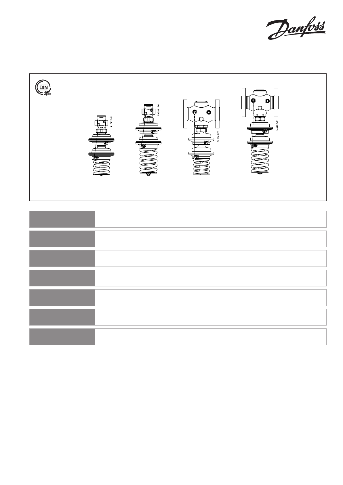
SAVD – PN 25 / DN 15 - 50
DN 15 - 50 DN 15 - 50 DN 32 - 50 DN 32 - 50
p = 1 - 5 p = 2 - 8 p = 1 - 5 p = 2 - 8
p = 3 - 12 p = 3 - 12
ENGLISH
DANSK
DEUTSCH
ESPAÑOL
SLOVENŠČINA
POLSKI
РУССКИЙ
Safety pressure reduction controller
SAVD
Regulator for sikkerhedstrykreduktion
SAVD
Sicherheitsabsperrventil (SAV) mit Druckminderer
SAVD
Reductor de presión con función de seguridad
SAVD
Varnostni reducirni regulator nadtlaka
SAVD
Reduktor ciśnienia z funkcją bezpieczeństwa
SAVD
Регулятор давления «после себя» c функцией
безопасности SAVD
www.danfoss.com Page 5
www.danfoss.dk Side 6
www.danfoss.de Seite 7
www.danfoss.es Page 8
www.danfoss.si Stran 9
www.danfoss.pl Strona 10
www.danfoss.ru Стр. 12
73695090 DH -SMT/SI VI.DC .E2.8M © Danf oss04/2011 1
Page 2
❺
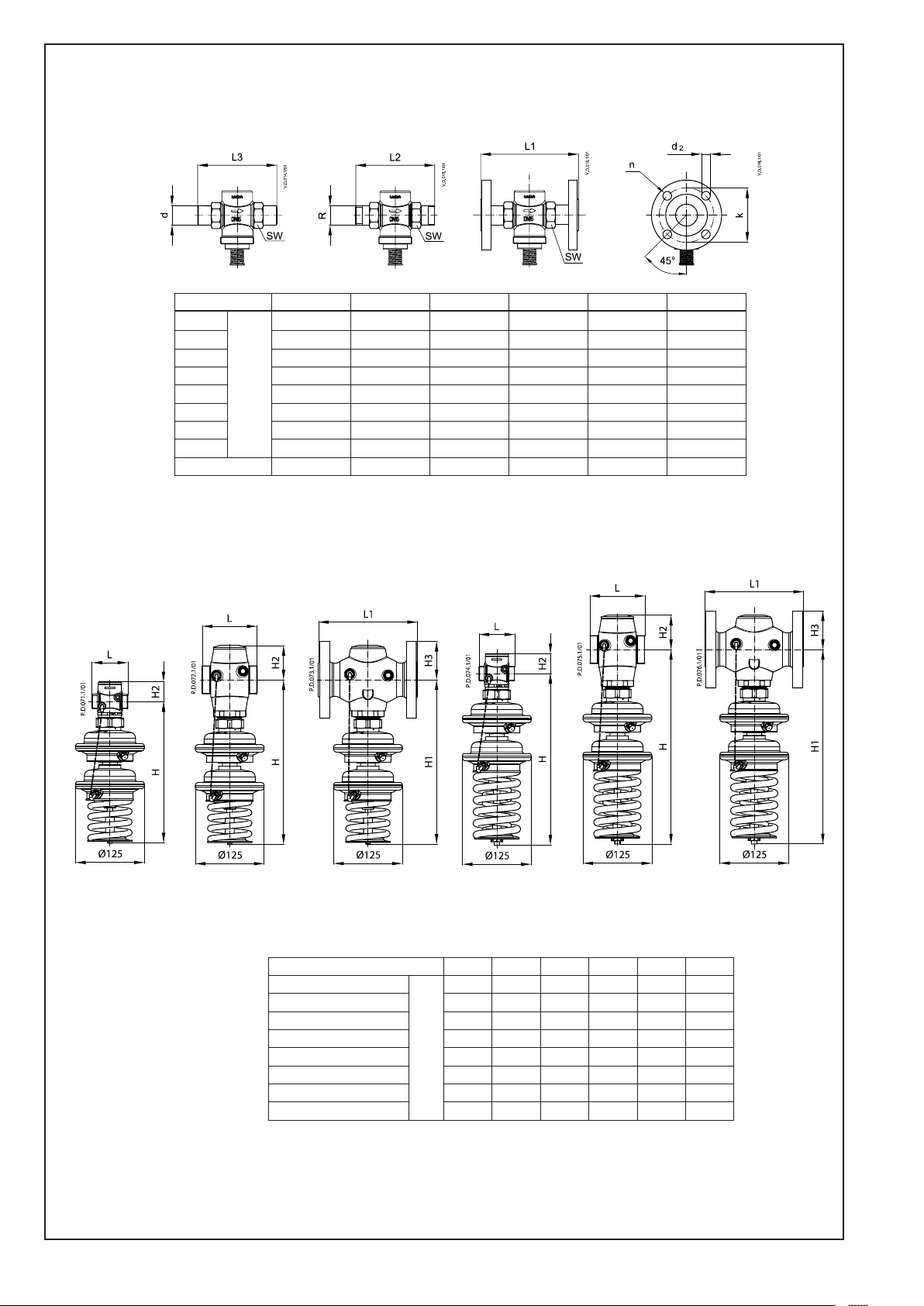
DN 15 20 25 32 40 50
SW
d 21 26 33 42 47 60
R 1) ⁄ ⁄ 1 1⁄ - L1 2) 130 150 160 - - L2 131 144 160 177 - L3 139 154 159 184 204 234
k 65 75 85 100 110 125
d2 14 14 14 18 18 18
n 4 4 4 4 4 4
32 (G ¾A) 41 (G 1A) 50 (G 1¼A) 63 (G 1¾A) 70 (G 2A) 82 (G 2½A)
mm
DN 15 - 25 DN 32 - 50 DN 32 - 50 DN 15 - 25 DN 32 - 50 DN 32 - 50
∆p = 1 - 5 ∆p = 1 - 5 ∆p = 1 - 5 ∆p = 2 - 8 ∆p = 2 - 8 ∆p = 2 - 8
∆p = 3 - 12 ∆p = 3 - 12 ∆p = 3 - 12
DN 15 20 25 32 40 50
L
L1 - - - 180 200 230
H ∆p = 1 - 5 257 257 257 299 299 299
H ∆p = 2 - 8 / 3 - 12 313 313 313 355 355 355
H1 ∆p = 1 - 5 - - - 299 299 299
H1 ∆p = 2 - 8 / 3 - 12 - - - 355 355 355
H2 34 34 37 62 62 62
H3 - - - 70 75 82
73695090 DH -SMT/SI VI.DC .E2.8M © Danf oss04/2011 2
mm
65 70 75 100 110 130
Page 3
❶
❸
①
①
②
❷
❹
②
①
③
④
②
⑤
⑥
③
DN L (mm)
15 69
20 74
25 79
32 104
40 114
50 134
⑦
⑧
①
❻
⑤
①
③
②
73695090 DH -SMT/SI VI.DC .E2.8M © Danf oss04/2011 3
④
Page 4
❼ ❽
①
∆p = 1.0 - 5.0 bar
①
⑤
17 mm
⑥
④
❾
③
②
③
④
②
①
73695090 DH -SMT/SI VI.DC .E2.8M © Danf oss04/2011 4
Page 5
ENGLISH
Safety Notes
Prior to assembly and commissioning
to avoid injury of persons and damages
of the devices, it is absolutely necessary
to carefully read and observe these
instructions.
Necessary assembly, start-up, and
maintenance work must be performed
only by qualified, trained and authorized
personnel.
Prior to assembly and maintenance work
on the controller, the system must be:
- depressurized,
- cooled down,
- emptied and
- cleaned.
Please comply with the instructions of the
system manufacturer or system operator.
Definition of Application
The controller is used for pressure
reduction control and as a protection
against excess pressure behind the valve.
The controller is used for water and water
glycol mixtures for heating, district heating
and cooling systems.
Controller is design-tested according to
DIN 4747 (SAV) and the AGFW guidelines.
The technical parameters on the product
labels determine the use.
Disposal instruction
This product should be
dismantled and its
components sorted, if
possible, in various groups
before recycling or disposal.
Always follow the local disposal
regulations.
Assembly
The system must be protected behind
the safety pressure reducer by a safety
monitoring unit SV ① or SÜV ②.
Secure the shut-off unit ③ against
unauthorized opening.
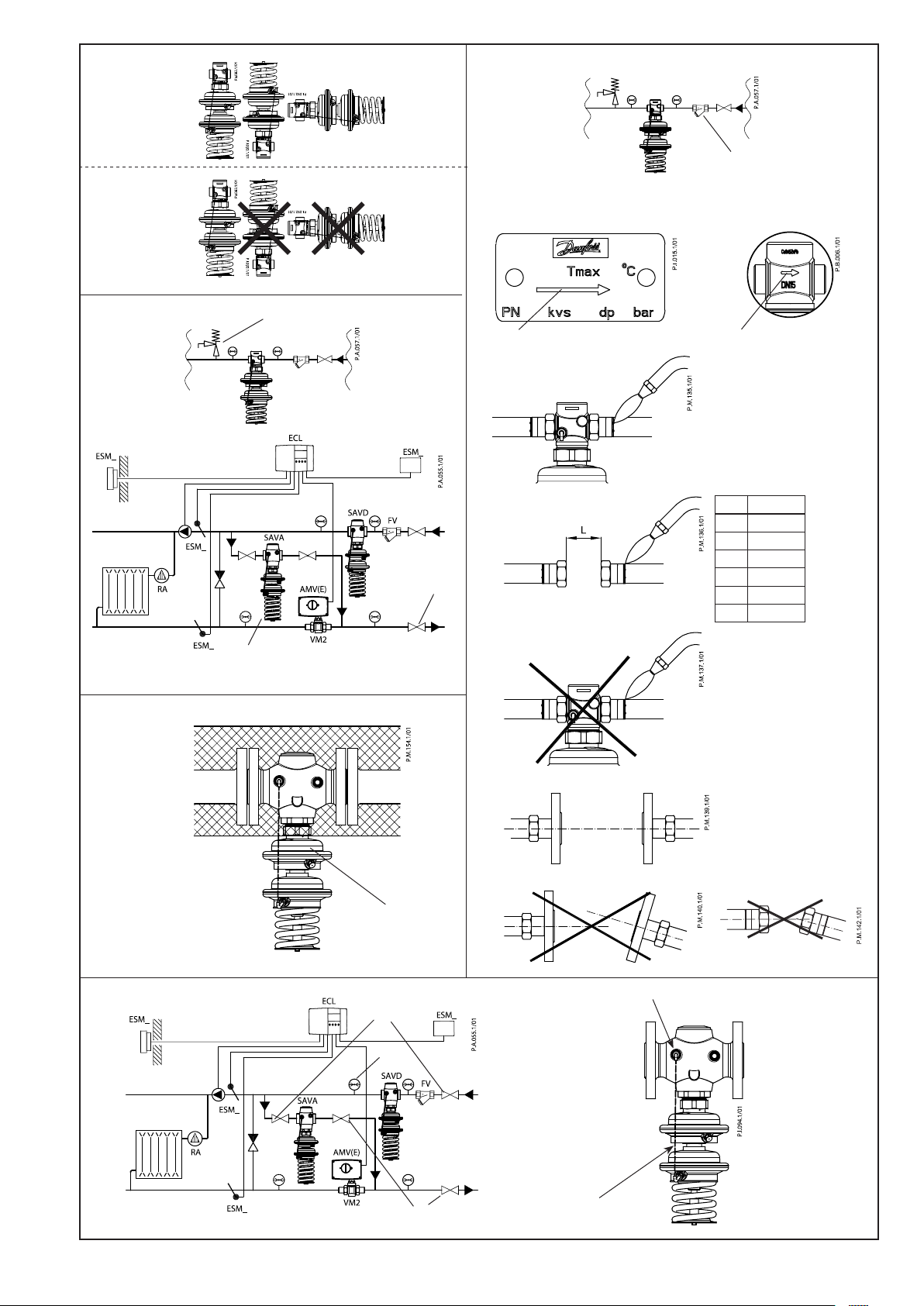
Valve Installation ➌
1. Clean pipeline system prior to assembly.
2. Install a strainer in front of the
controller ①.
Max. mesh width
DN 15 - 25: 0.5 mm
DN 32 - 50: 0.8 mm
3. Install pressure indicators in front of and
behind the system part to be controlled.
4. Install valve
• The flow direction indicated on the
product label ② or on the valve ③
must be observed.
• The valve with mounted weld-on
tailpieces may only be spot welded to
the pipeline ④.
The weld-on tailpieces may be welded
only without the valve and seals! ⑤⑥
If these instructions are not observed,
high welding temperatures may
destroy the seals.
• Flanges ⑦ in the pipeline must be in
parallel position and sealing surfaces
must be clean and without any
damage.
Tighten screws in flanges crosswise
in 3 steps up to the maximum torque
(50 Nm).
5. Caution:
Mechanical loads of the valve body by the
pipelines are not permitted ⑧.
Insulation ➍
Do not insulate the pressure actuator ①.
Dimensions, Weights ❺
(See page 2)
1)
Conical ext. thread acc. to EN 10226-1
2)
Flanges PN 25, acc. to EN 1092-2
Leak and Pressure Tests
To avoid inadmissible pressures on the
actuator (admissible excess pressure during
operation is 14 bar) it is absolutely necessary
to remove the impulse tube ④. Close
connections with plugs G ⁄ ISO 228 ⑤. In
this case valve is always closed.
Pressure must be gradually increased at
the +/- connection.
Non-compliance may cause damages at
the actuator or the valve.
A pressure test of the entire system
must be carried out in accordance with
manufacturer’s instructions.
The maximum test pressure is: 1.5 × PN
PN - see product label!
Putting out of operation
1. Slowly close shut-off devices ① in the
flow pipeline.
2. Slowly close shut-off devices ② in the
return pipeline.
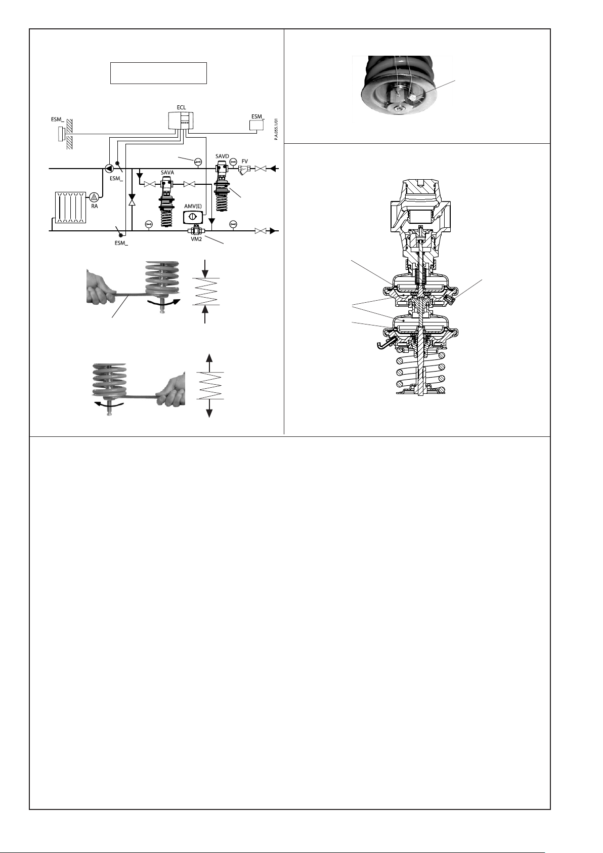
Settings ❼
Pressure Setting
The pressure setting range is indicated on
the product label ①.
Procedure:
1. Set flow rate on a motorized valve ②
after the safety pressure reducer ③ to
about 50 % of the max. flow rate.
2. Adjustment
(of the pressure behind the valve)
Observe pressure indicators ④.
• Turning to the right ⑤ (clockwise)
increases the set-point (stressing the
spring).
• Turning to the left ⑥ (counterclockwise) reduces the set-point
(releasing the spring).
Admissible Installation Positions ❶
Medium temperatures up to 100 °C:
- Can be installed in any position ①.
Medium temperatures > 100 °C:
- Installation permitted only in
horizontal pipelines with the actuator
oriented downwards ②.
Start-up ❻
The valve is opened without pressure. The
valve closes when the pressure behind
the valve ③ rises above the adjusted
set-point.
Installation Location and
Installation Scheme ❷
SAVD mounting
73695090 DH -SMT/SI VI.DC .E2.8M © Danf oss04/2011 5
Filling the system, first start-up
1. Slowly open shut-off devices ① in the
flow pipeline.
2. Slowly open shut-off device ② in the
return pipeline.
Seal ❽
The set-point adjuster can be sealed by a
seal wire ①, if necessary.
Safety function ❾
If the control diaphragm ① beaks, pressure
gets in the two intermediate chambers ②.
This pressure acts upon the safety
diaphragm ③ and causes the following:
- The valve closes
- The control function does not operate
- A slight water leakage at the threaded
joint ④ of the upper casing indicates a
break of the diaphragm.
The controller must be replaced when the
diaphragm is broken.
Page 6

DANSK
Sikkerhedsnoter
Disse instruktioner SKAL læses
omhyggeligt forud for montering og
indkøring samt respekteres for at undgå
skader på personer og udstyr.
Nødvendigt monterings-, opstart- og
vedligeholdelsesarbejde må kun udføres af
faglært og autoriseret personale.
Forud for monterings- og
vedligeholdelsesarbejde på regulatoren
skal systemet være:
- trykløst,
- nedkølet,
- tømt og
- rengjort.
Systemproducentens eller -operatørens
instruktioner skal overholdes.
Anvendelse
Regulatoren anvendes til
trykreduktionsstyring og som
beskyttelse mod overtryk bag ventilen.
Regulatoren anvendes til vand og vandglycolblandinger til varme-, ernvarme- og
kølesystemer.
De tekniske parametre på
produktetiketterne fastlægger
anvendelsen.
Bortskaffelsesinstruktion
Dette produkt skal, om
muligt, adskilles og sorteres i
dets forskellige
materialegrupper, før det
genbruges eller bortskaffes.
Lokal lovgivning for bortskaffelse skal
altid overholdes.
Montering
Ventilinstallation ➌
1. Rengør rørledningssystemet før
montering.
2. Installer et filter før regulatoren ①.
Maks. maskevidde
DN 15 - 25: 0,5 mm
DN 32 - 50: 0,8 mm
3. Installer trykvisere før og efter den
systemdel, der skal reguleres.
4. Installer ventilen
• Den flowretning, der vises på
produktetiketten eller på ventilen, skal
respekteres ② ③.
• Ventilen med monterede
svejsestudser må kun klemmes fast til
rørledningen ④.
Svejsestudserne må kun svejses uden
ventil og pakninger! ⑤⑥
Høje svejsetemperaturer kan
ødelægge pakningerne, hvis disse
instruktioner ikke overholdes.
• Flanger ⑦ i rørledningen skal være
placeret parallelt, og pakfladerne
skal være rene og uden skader.
Krydsspænd skruerne i flangerne i 3
trin til maks. moment (50 Nm).
5. Forsigtig:
Ventilhuset må ikke udsættes for
mekaniske belastninger fra rørsystemet ⑧.
Isolering ➍
Trykaktuatoren ① må ikke isoleres.
Mål, vægt ❺
(See page 2)
1)
Konisk udv. gevind iht. EN 10226-1
2)
Flanger PN 25 iht. EN 1092-2
Opstart ❻
Ventilen åbnes uden tryk. Ventilen lukker,
når trykket bag ventilen ③ overstiger det
indstillede sætpunkt.
Trykket skal øges gradvist ved
+/- tilslutningen
Overholdes dette ikke, kan der opstå
skader på aktuatoren eller ventilen.
Der skal udføres en trykprøvning af
hele systemet i overensstemmelse med
producentens instruktioner.
Det maksimale prøvetryk er: 1,5 × PN
PN fremgår af produktetiketten!
Standsning
1. Luk langsomt for
afspærringsanordningerne ① i
flowledningen.
2. Luk langsomt for
afspærringsanordningerne ② i
returledningen.
Indstilling af sætpunkter ❼
Trykindstilling
Trykindstillingsområdet fremgår af
produktetiketten ①.
Fremgangsmåde:
1. Indstil flowhastigheden ved
en afspærringsventil ② efter
sikkerhedstrykregulatoren ③ ttil ca. 50
% af den maksimale flowhastighed.
2. Justering
(af trykket bag ventilen)
Aflæs trykviserne ④.
• Drejes der til højre ⑤, øges
sætpunktet (ederen spændes).
• Drejes der til venstre ⑥, reduceres
sætpunktet (ederen udløses).
Plombering ❽
Sætpunktsstilleskruen kan om nødvendigt
forsegles med en plombe ①.
Tilladelige installationsstillinger ❶
Medietemperaturer op til 100 °C:
- Kan monteres i alle stillinger ①.
Medietemperaturer > 100 °C:
- Må kun installeres i vandrette
rørledninger og med aktuatoren
hængende nedad ②.
Påfyldning af systemet, første
opstart
1. Åbn langsomt for
afspærringsanordningerne ① i
flowledningen.
2. Åbn langsomt for
afspærringsanordningerne ② i
returledningen.
Installationsplacering og
installationsplan ❷
SAVD-montering
Systemet skal beskyttes af en
sikkerhedsovervågningsenhed SV ① eller
SÜV ②bag sikkerhedstrykregulatoren.
Sørg for, at afspærringsenheden ③ ikke
kan åbnes uautoriseret.
73695090 DH -SMT/SI VI.DC .E2.8M © Danf oss 04/2011 6
Lækage- og trykprøvning
For at undgå utilladeligt høje tryk på
aktuatoren (tilladeligt overtryk under drift
er 14 bar) er det absolut nødvendigt at
erne impulsledningen ④. Luk tilslutninger
med propper G 1⁄8 ISO 228 ⑤.
Sikkerhedsfunktion ❾
Hvis reguleringsmembranen ① brister,
kommer der tryk i de to mellemkamre ②.
Dette tryk påvirker sikkerhedsmembranen
③ og medfører følgende:
- Ventilen åbner
- Styringsfunktionen virker ikke
- En mindre vandlækage ved
gevindsamlingen ④ til den øverste del
af huset indikerer, at membranen er
bristet.
Regulatoren skal udskiftes, hvis
membranen er bristet.
Page 7

DEUTSCH
Sicherheitshinweise
Um Verletzungen an Personen und
Schäden am Gerät zu vermeiden, ist diese
Anleitung vor der Montage unbedingt zu
beachten.
Montage, Inbetriebnahme und
Wartungsarbeiten dürfen nur von
sachkundigen und autorisierten Personen
durchgeführt werden.
Vor Montage und Wartungsarbeiten am
Regler die Anlage:
- drucklos machen,
- abkühlen,
- entleeren und
- reinigen.
Die Vorgaben des Anlagenherstellers und
Anlagenbetreibers sind zu beachten.
Bestimmungsgemäße Verwendung
Der Regler verhindert durch selbsttätiges
Schließen die Überschreitung des
Druckes nach dem Ventil von Wasser und
Wasser-Glykol-Gemischen in Heizungs-,
Fernheizungs- und Kühlungsanlagen.
Bauteilgeprüft nach AGFW Arbeitsblatt
FW 504 (SAV).
Die technischen Daten auf den
Typenschildern sind für den Einsatz
maßgebend.
Anweisung zur Entsorgung
Dieses Produkt sollte
ausgebaut und in dessen
Bestandteile zerlegt werden.
Sortieren Sie die einzelnen
Bestandteile entsprechend
der Entsorgungsgruppen zur
Wiederverwertung oder Entsorgung.
Beachten sie dabei immer die lokalen
Entsorgungsrichtlinien.
Die Anlage muss durch eine
Sicherheitsarmatur (SV ① oder SÜV ②)
hinter dem Druckminderer abgesichert
werden.
Absperrarmatur ③ gegen unbefugtes
Schließen sichern.
Einbau Ventil ➌
1. Rohrleitung vor der Montage reinigen.
2. Schmutzfänger ① vor dem Regler
einbauen.
Max. Maschenweite
DN 15 - 25: 0,5 mm
DN 32 - 50: 0,8 mm
3. Druckanzeiger vor und hinter dem
Ventil bzw. den entsprechenden
Anlageteilen einbauen.
4. Ventil einbauen
• Durchflussrichtung ② auf dem
Typenschild oder Ventil beachten ③.
• Ventil mit angeschraubten
Anschweißenden nur an die
Rohrleitung anheften ④.
Das Einschweißen der
Anschweißenden ist nur ohne Ventil
und Dichtungen zulässig! ⑤⑥
Bei Nichtbeachtung zerstören die
hohen Schweißtemperaturen die
Dichtungen des Ventils.
• Flansche ⑦ in der Rohrleitung müssen
parallel, Dichtflächen sauber und ohne
Beschädigungen sein.
Schrauben über Kreuz in 3 Stufen bis
zum max. Drehmoment anziehen
(50 Nm).
5. Achtung:
Mechanische Belastungen des
Ventilgehäuses durch die Rohrleitungen
sind nicht zulässig ⑧.
Isolierung ➍
Druckantrieb ① nicht isolieren.
Dichtheits- und Druckprüfung
Um unzulässig hohen Druck am
Druckantrieb zu vermeiden (zulässiger
Überdruck während des Betriebs ist 14
bar), ist es erforderlich, die Steuerleitung ④
zu entfernen. Die Anschlüsse mit einer
Plombe G ⁄ ISO 228 ⑤ schließen.
Die Druckerhöhung muss am +/Anschluss gleichmäßig erfolgen.
Nichtbeachtung kann zu Schäden am
Antrieb und/oder Ventil führen.
Die Druckprüfung der Anlage muss nach
den Vorgaben des Anlagenherstellers
durchgeführt werden.
Max. Prüfdruck ist: 1,5 × PN
PN siehe Typenschild!
Außerbetriebnahme
1. Absperrarmaturen ① im Vorlauf
langsam schließen.
2. Absperrarmaturen ② im Rücklauf
langsam schließen.
Einstellung Sollwerte ❼
Druckeinstellung
Sollwertbereich siehe Typenschild ①.
Vorgehensweise:
1. Volumenstrom an einer Armatur ②
hinter dem Druckminderer ③ auf
ca. 50 % des max. Volumenstroms
einstellen.
2. Einstellung
(des Druckes hinter dem Ventil)
Druckanzeigen ④ beachten.
• Rechtsdrehung ⑤ erhöht den Sollwert
(Feder spannen).
• Linksdrehung ⑥ reduziert den
Sollwert (Feder entspannen).
Abmessungen, Gewichte ❺
Montage
Zulässige Einbaulagen ❶
Mediumstemperaturen bis 100 °C:
- Einbaulage beliebig ①.
Mediumstemperaturen 100 °C:
- Einbau nur in waagerechte Rohrleitung
mit nach unten hängendem Antrieb
zulässig ②.
Einbauort, Einbauschema ❷
SAVD Einbau
(See page 2)
1)
Kegeliges Außengewinde nach
EN 10226-1
2)
Flansche PN 25, nach EN 1092-2
Inbetriebnahme ❻
Ohne Druck bleibt das Ventil geöffnet. Das
Ventil schließt, wenn der Druck hinter dem
Ventil ③ über den eingestellten Sollwert
steigt.
Füllung der Anlage, Inbetriebnahme
1. Absperrarmaturen ① im Vorlauf
langsam öffnen.
2. Abperrarmaturen ② im Rücklauf
langsam öffnen.
73695090 DH -SMT/SI VI.DC .E2.8M © Danf oss04/2011 7
Plombierung ❽
Bei Bedarf kann der Sollwertsteller ①
durch Plombierdraht gesichert werden.
Sicherheitsfunktion ❾
Bei einem Membranbruch der
Regelmembrane ① wird in den beiden
Zwischenkammern ② ein Druck
aufgebaut. Der Druck wirkt auf die
Sicherheitsmembrane ③ dadurch:
- wird das Ventil geschlossen
- ist die Regelfunktion außer Betrieb
- Anzeige des Membranbruchs durch
geringen Wasseraustritt an der
Verschraubung ④.
Der Regler muss nach einem
Membranbruch ausgetauscht werden.
Page 8

ESPAÑOL
Notas de seguridad
El sistema debe protegerse detrás del
Antes del montaje y de la puesta en
marcha, para evitar daños personales
y perjuicios en los dispositivos,
es absolutamente necesario leer
cuidadosamente estas instrucciones.
El montaje, la puesta en marcha y el trabajo
de mantenimiento necesario deberán ser
realizados solo por personal cualificado y
autorizado.
Antes del montaje y el trabajo de
mantenimiento del controlador, el sistema
debe ser:
- despresurizado
- enfriado,
- vaciado y
- limpiado.
Por favor, cumpla con las instrucciones del
fabricante del sistema o del operador del
sistema.
Aplicación
El regulador se utiliza para el control de
la reducción de presión y como proteccón
contra el exceso de presión después de
la válvula. El regulador se utiliza para
agua y mezcla agua/glycol en sistemas
de Calefacción, District Heating y
Refrigeración.
Los parámetros técnicos en la etiquetas del
producto determinan su uso.
Instucciones de eliminación
Este producto debe ser
desmontado y si es posible,
sus componentes deben ser
separados en varios grupos
antes de su reciclado o
destrucción.
Siga siempre la regulación local sobre
eliminación.
reductor de presión con función de
seguridad por una unidad de seguridad
(SV, SÜV) ① ②.
Unidad de cierre de seguridad ③ contra la
apertura no autorizada.
Instalación de la válvula ➌
1. Limpie el sistema de tuberías antes del
montaje.
2. Instale un filtro antes del regulador ①.
Anchura máx.:
DN 15 - 25: 0.5 mm
DN 32 - 50: 0.8 mm
3. Instale indicadores de presión delante
y detrás de la parte del sistema a
controlar.
4. Instale la válvula
• Observe la dirección del caudal
indicada en la etiqueta del producto o
en la válvula ② ③.
• La válvula con conectores para soldar
solo pueden ser fijados a la tubería ④.
Los conectores para soldar solo
pueden soldarse sin la válvula y sin
sellos! ⑤⑥
Si estas instrucciones no se tienen en
cuenta, las altas temperaturas al soldar
pueden destruir los sellos.
• Las bridas ⑦ en la tubería deben estar
en posición paralela y las superficies
que sellan deben estar limpias y sin
ningún daño.
Apriete los tornillos en las bridas en
diagonal en 3 pasos hasta el máximo
(50 Nm).
5. Precaución:
No se permiten cargas mecánicas del
cuerpo de la válvula ⑧.
Aislamiento ➍
No aísle el actuador de presión ①.
Dimensiones, Pesos ❺
(See page 2)
Montaje
1)
Rosca externa cónica acc. to EN 10226-1
2)
Bridas PN 25, acc. to EN 1092-2
Posiciones permitidas de
instalación ❶
Temperatura del medio hasta 100 °C:
- Puede ser instalado en cualquier
posición ①.
Temperatura del medio > 100 °C:
- Instalación permitida sólo en
horizontal con el actuador hacia
abajo ②.
Posición de instalación y Esquema
de instalación ❷
SAVD montaje
73695090 DH -SMT/SI VI.DC .E2.8M © Danf oss 04/2011 8
Puesta en marcha ❻
La válvula está abierta si no hay presión.
La válvula cierra cuando la presión
después de la válvula ③ sobrepasa el
valor fijado.
Llenado del sistema, primera puesta
en marcha
1. Abra lentamente todos los dispositivos
de corte ① en la tubería de impulsión.
2. Abra lentamente todos los dispositivos
de corte ② en la tubería de retorno.
Escapes y Pruebas de presión
Para evitar presiones inadmisibles en el
actuador (el exceso de presión admisible
durante el funcionamiento 14 bar) es
absolutamente necesario quitar el tubo
de impulsión ④. Conexiones cerradas G ⁄
ISO 228 ⑤. En este caso la válvula está
siempre cerrada.
La presión debe ir aumentando
gradualmente en la conexión +/- .
El incumplimiento puede causar daños en
el actuador o la válvula.
Una prueba de presión del sistema
completo debe ser realizada de acuerdo
con las instrucciones del fabricante.
La presión máxima de prueba es: 1.5 × PN
PN ver etiqueta del producto!
Fuera de operación
1. Cierre lentamente los dispositivos de
corte ① en la tubería de impulsión.
2. Cierre lentamente los dispositivos de
corte ② en la tubería de retorno.
Ajustes ❼
Ajuste de la presión
El rango de ajuste de la presión se indica en
la etiqueta del producto ①.
Procedimiento:
1. Fije el caudal en la válvula de cierre ②
después del reductor de presión ③ en
aproximadamente el 50 % del caudal
máximo.
2. Ajuste
(de la presión detrás de la válvula)
Observe los indicadores de presión ④.
• Girando a la derecha ⑤ aumenta el
punto de ajuste (comprimiendo el
muelle).
• Girando a la izquierda ⑥ reduces el
punto de ajuste (relajando el muelle).
Sellado ❽
El punto de ajuste fijado puede sellarse con
un alambre sellado ①, i fuera necesario.
Función de seguridad ❾
Si el diafragma de control ① se rompe, la
presión llega en las dos cámaras intermedias ②.
Esta presión actúa sobre el diafragma de
seguridad ③ y ocurre lo siguiente:
- La válvula abre
- La función de control no funciona
- Una pérdida leve de agua a través de la
unión roscada ④ de la cubierta superior
indica la rotura del diafragma.
El regulador debe ser substituido cuando el
diafragma se rompe.
Page 9

SLOVENŠČINA
Varnostna opozorila
Izjemno pomembno je, da pred montažo
in zagonom skrbno preberete navodila in
se jih držite. S tem se izognete poškodbam
ljudi in okvaram na opremi.
Nujna sestavna, zagonska in vzdrževalna
dela lahko izvajajo samo kvalificirani, šolani
in pooblaščeni delavci.
Pred sestavo in vzdrževalnimi deli na
regulatorju mora biti sistem:
- tlačno izravnan,
- ohlajen,
- izpraznjen in
- očiščen.
Prosimo, upoštevajte navodila proizvajalca
sistema ali sistemskega operaterja.
Opis naprave
Regulator se uporablja za reduciranje tlaka
in kot zaščita proti previsokemu tlaku za
ventilom v sistemih ogrevanja, daljinskega
ogrevanja in hlajenja napolnjenih z vodo ali
z mešanico vode in glikola.
Tehnični podatki na etiketi izdelka določajo
uporabo.
Navodila za rokovanje z odsluženim
izdelkom
Pred recikliranjem ali
odlaganjem odsluženega
izdelka na odpad, ga je
potrebno razstaviti in
njegove sestavne dele, če je
le mogoče, sortirati po
skupinah.
Vedno upoštevajte lokalno zakonodajo
glede rokovanja z odpadki.
Montaža
Sistem za varnostnim reducirnim
ventilom mora biti varovan z varnostnim
nadzornikom SV ① or SÜV ②.
Preprečite nepooblaščeno odpiranje
zapornega ventila ③.
Vgradnja ventila ➌
1. Pred montažo očistite cevovod.
2. Pred regulator ① vgradite čistilni kos.
Maksimalna delitev mrežice:
DN 15 - 25: 0,5 mm
DN 32 - 50: 0,8 mm
3. Vgradite manometer pred in za sistem,
ki ga regulirate.
4. Vgradite ventil
• Upoštevajte puščico na etiketi
proizvoda oz. na proizvodu samem, ki
kaže smer pretoka ② ③.
• Ventil z vgrajenimi varilnimi priključki
se lahko samo pritrdi na cevovod ④.
Varilni priključki so nato lahko polno
varjeni samo brez ventila in tesnil! ⑤⑥
Ob neupoštevanju teh navodil lahko
visoke temperature pri varjenju uničijo
tesnila.
• Protiprirobnice ⑦ morajo biti
vzporedne, tesnilne površine morajo
biti čiste.in brez poškodb.
Pritegnite vijake na prirobnicah križem
v treh korakih do maksimalnega
momenta (50 Nm).
5. Opozorilo:
Mehanske obremenitve cevovoda na telo
ventila niso dovoljene ⑧.
Izolacija ➍
Tlačnega pogona ① ne izolirajte.
Dimenzije, masa ❺
(Glej stran 2)
1)
Konični zunanji navoj po EN 10226-1
2)
Prirobnice PN 25, glede na EN 1092-2
Test tesnosti in tlaka
Da bi preprečili nedopustno visoke tlake na
tlačnem pogonu (dopusten nadtlak med
delovanjem je 14 bar) je med preizkusom
absolutno potrebno odstraniti impulzno
cev ④. Priključke zaprite s čepi z navojem
G ⁄ ISO 228 ⑤. V tem primeru je ventil
vseskozi zaprt.
Na priključkih mora tlak naraščati
postopoma +/- .
Neskladnost z navodili lahko povzroči
poškodbe na pogonu ali na ventilu.
Tlačni preizkus celotnega sistema se mora
izvajati po navodilih proizvajalca..
Maksimalni preizkusni tlak je: 1,5 × PN
PN glejte napisno ploščico!
Jemanje iz obratovanja
1. Počasi zaprite zaporne organe ① v
dovodu.
2. Počasi zaprite zaporne organe ② v
povratku.
Nastavitev regulatorja ❼
Nastavitev nadtlaka
Področje nastavitev nadtlaka je prikazano
na etiketi na ohišju ①.
Postopek:
1. Nastavite pretok na zapornem ventilu
② za reducirnim ventilom ③ na okrog
50 % nazivnega pretoka.
2. Nastavitev tlaka za ventilom
Opazujte indikator tlaka ④.
• Z obračanjem v desno ⑤ (povišate
nastavitveno točko tlaka (napenjate
vzmet).
• Vrtenje v levo ⑥ znižuje nastavitveno
točko (sprostite vzmet).
Dopustni položaji vgradnje ❶
Temperatura medija do 100 °C:
- Lahko se vgradi v kateremkoli
položaju ①.
Temperatura medija > 100 °C:
- Vgradnja dovoljena samo v
horizontalni položaj tako, da je pogon
obrnjen navzdol. ②.
Lokacija namestitve in shema
vgradnje ❷
SAVD vgradnja v dovod
73695090 DH -SMT/SI VI.DC .E2.8M © Danf oss04/2011 9
Zagon ❻
TVentil je brez tlaka odprt. Ventil zapira
kadar tlak za ventilom ③ naraste nad
nastavljeno vrednost.
Polnjenje sistema, prvi zagon
1. Počasi odprite zaporne ventile v
povratnem vodu ①.
2. Počasi odprite zaporne ventile v
dovodnem cevovodu ②.
Plombiranje ❽
Element za nastavitev diferenčnega tlaka se
lahko plombira s plombirno žico ①, če je to
zahtevano.
Varnostna funkcija ❾
Če se regulacijska membrana ① poškoduje,
tlak v vmesnem prostoru ② naraste. Ta
tlak deluje na varnostno membrano ③ in
povzroči naslednje:
- Ventil se zapre
- Delovna regulacija tlaka ne deluje
- Majhno puščanje na navojnem stiku ④
zgornjega ohišja nakazuje poškodbo
delovne membrane.
Ob poškodbi membrane je potrebno
regulator zamenjati.
Page 10

POLSKI
Warunki bezpieczeństwa
W celu uniknięcia zranienia osób
i uszkodzenia urządzeń należy
bezwzględnie przed montażem i
uruchomieniem zaworu zapoznać się
dokładnie z niniejszą instrukcją.
Czynności związane z montażem,
uruchomieniem i obsługą mogą
być dokonywane wyłącznie przez
osoby uprawnione i odpowiednio
wykwalifikowane.
Przed montażem i obsługą konserwacyjną
regulatora należy:
- zrzucić ciśnienie,
- ostudzić urządzenia,
- opróżnić układ,
- oczyścić.
Prosimy stosować się do instrukcji
producenta lub operatora układu.
Zastosowanie
Regulator jest stosowany do redukcji
ciśnienia oraz dla ochrony przed
nadmiernym ciśnieniem za zaworem.
Regulator jest stosowany dla wody i
roztworów wody z glikolem w instalacjach
grzewczych, sieciach cieplnych i
instalacjach chłodzenia.
Regulator zaprojektowany i badany zg. z
DIN 4747 (SAV) i wytycznymi AGFW.
Instrukcja usuwania odpadów
Ten produkt powinien być
rozebrany a jego
komponenty
posegregowane, jeśli to
możliwe, na różne grupy
przed poddaniem
recyklingowi lub utylizacji.
Zawsze stosuj się do miejscowych
przepisów w zakresie usuwania
odpadów.
Montaż
Miejsce i schemat montażu ❷
Montaż SAVD
Układ za reduktorem z funkcją
bezpieczeństwa musi być wyposażony w
zawór bezpieczeństwa SV ① albo SÜV ②.
Należy zabezpieczyć armaturę
odcinającą ③ przed otwarciem przez
osoby niepowołane.
Montaż zaworu ➌
1. Przed zamontowaniem zaworu
przepłukać instalację.
2. Przed regulatorem zamontować filtr ①.
Max. rozmiar oczek siatki
DN 15 - 25: 0,5 mm
DN 32 - 50: 0,8 mm
3. Zamontować manometry przed i
za tą częścią układu, która będzie
regulowana.
4. Zamontować zawór.
• Należy zachować kierunek przepływu
zaznaczony na tabliczce znamionowej
lub na korpusie zaworu ② ③.
• Zawór z zamocowanymi końcówkami
do przyspawania może być tylko
punktowo przyspawany do
rurociągu ④.
Końcówki mogą być przyspawane
tylko bez zaworu i uszczelnienia! ⑤⑥
Nie zastosowanie się do tego zalecenia
może spowodować uszkodzenie
uszczelnień wskutek wysokiej
temperatury.
• Kołnierze ⑦ na rurociągu muszą
być równoległe a powierzchnie pod
uszczelki czyste i bez uszkodzeń.
Dokręcać śruby przy kołnierzach po
przekątnej, w trzech krokach, aż do
uzyskania maksymalnego momentu
(50 Nm).
5. Uwaga:
Nie można dopuścić do powstania
mechanicznych obciążeń korpusu zaworu
od rurociągów ⑧.
Izolacja. ➍
Nie izolować siłownika ①.
Uruchomienie ❻
Bez oddziaływania ciśnienia zawór
pozostaje otwarty. Zawór zamyka się,
kiedy ciśnienie ③ za zaworem wzrasta
powyżej nastawionej wartości.
Napełnienie układu, pierwsze
uruchomienie.
1. Powoli otworzyć zawory odcinające ①
na rurociągu zasilającym.
2. Powoli otworzyć zawory odcinające ②
na rurociągu powrotnym.
Próby szczelności i ciśnienia.
Dla uniknięcia nadmiernego ciśnienia
na siłowniku (dopuszczalne cinienie
nadmiarowe w czasie pracy wynosi 14
bar) należy koniecznie odłączyć rurkę
impulsową ④. Podłączenia zamknąć
korkami G ⁄ ISO 228 ⑤.
Ciśnienie na podłączeniach +/- należy
zwiększać stopniowo.
Nie przestrzeganie powyższych zasad
może spowodować uszkodzenie siłownika
lub zaworu.
Próba ciśnienia dla całego układu musi
być przeprowadzona zgodnie z instrukcją
producenta lub projektanta.
Maksymalne ciśnienie próbne wynosi:
1,5 × PN
Ciśnienie nominalne PN podano na
tabliczce znamionowej urządzenia.
Odłączenie zaworu.
1. Powoli zamknąć armaturę odcinającą ①
na rurociągu zasilającym.
2. SPowoli zamknąć armaturę
odcinającą ② na rurociągu powrotnym.
Dopuszczalne pozycje montażu. ❶
Temperatury czynnika do 100 °C:
- montaż w dowolnej pozycji ①.
Temperatury czynnika > 100 °C:
- Montaż dozwolony tylko na rurociągu
poziomym, z siłownikiem skierowanym
w dół ②.
73695090 DH -SMT/SI VI.DC .E2.8M © Danf oss 04/2011 10
Dimensions, Weights ❺
(See page 2)
1)
Stożkowy gwint zewnętrzny wg
EN 10226-1
2)
Kołnierze PN 25 wg EN 1092-2
Page 11

Nastawy. ❼
Nastawa ciśnienia.
Zakres nastawy ciśnienia podano na
tabliczce znamionowej zaworu ①.
Tok postępowania:
1. Ustawić przepływ zaworem
regulacyjnym ② przez zawór
redukcyjny ③, na ok. 50% przepływu
maksymalnego.
2. Dokonać nastawienia
(ciśnienia za zaworem).
Obserwować wskazania manometru ④.
• Obracanie w prawo ⑤ zwiększa
wartość nastawy (ściskanie sprężyny).
• Obracanie w lewo ⑥ zmniejsza
wartość nastawy (luzowanie sprężyny).
Plomba. ❽
Nakrętka nastawcza może zostać w razie
potrzeby zaplombowana ①.
Funkcja bezpieczeństwa. ❾
Jeżeli membrana regulująca ① przecieka,
ciśnienie przedostaje się do dwóch
komór pośrednich ② i oddziaływując na
membranę bezpieczeństwa ③ powoduje:
- zamknięcie zaworu,
- zaprzestanie działania regulacyjnego
zaworu,
- niewielki wypływ czynnika przez
gwintowane złącze ④ w górnej części
obudowy, wskazujący na przerwanie
membrany.
Jeżeli membrana jest przerwana, należy
wymienić regulator.
73695090 DH -SMT/SI VI.DC .E2.8M © Danf oss04/2011 11
Page 12

РУССКИЙ
Правила техники безопасности
Для предупреждения травматизма и
повреждения оборудования перед
началом производства работ по его
монтажу и вводу в эксплуатацию
следует изучить и соблюдать настоящую
инструкцию.
Монтаж, наладку и техническое
обслуживание оборудования может
выполнять только квалифицированный
персонал, имеющий допуск к таким
работам.
В целях соблюдения правил техники
безопасности перед началом работ по
монтажу или обслуживанию регулятора
необходимо произвести следующие
действия с трубопроводной системой:
- сбросить давление;
- охладить;
- опорожнить;
- прочистить.
При этом также должна соблюдаться
инструкция по эксплуатации системы.
Область применения
Регулятор используется для понижения
давления воды или водного раствора
гликоля после клапана и защиты от
превышения давления в системах
централизованного теплоснабжения или
охлаждения.
Условия применения регулятора
определяются техническими
характеристиками, указанными на
этикетке изделия.
Инструкция по утилизации
Данная продукция
подлежит демонтажу на
части, для раздельной
утилизации составных
компонентов.
Монтаж
Монтажные положения
регулятора ❶
Температура регулируемой среды до
100 °C:
- Регулятор может устанавливаться в
любом положении ①.
Температура регулируемой среды выше
100 °C:
- IУстановка регулятора разрешается
только на горизонтальном
трубопроводе регулирующим
элементом вниз ②.
Размещение регулятора и схема
установки ❷
Установка SAVD на подающем
трубопроводе
Система, находящаяся после
регулятора, должна быть защищена
с помощью предохранительных
устройств ① или ②.
Убедитесь что запорная арматура ③
защищена от несанкционированного
доступа.
Монтаж клапана ➌
1. Перед монтажом клапана промойте
трубопроводную систему.
2. До регулятора установите сетчатый
фильтр ① с максимальным размером
ячейки его сетки:
для Ду = 15-25 мм – 0,5 мм;
для Ду = 32-50 мм – 0,8 мм.
3. Для контроля давлений до и
после ррегулятора необходимо
предусмотреть показывающие
манометры.
4. Установите клапан так, чтобы
направление стрелки на этикетке
клапана ② или на его корпусе ③
совпадало с направлением движения
регулируемой среды.
• Резьбовой клапан монтируется с
помощью приварных фитингов,
которые при установленном
между ними клапане должны
предварительно фиксироваться на
трубопроводе прихваткой ④.
Окончательная приварка фитингов к
трубопроводу может производиться
только при отсутствии клапана и
уплотнительных прокладок! ⑤⑥
• При несоблюдении этих инструкций
высокая температура сварки может
повредить уплотнения фитингов и
самого клапана.
• Фланцы ⑦ на трубопроводе должны
быть установлены параллельно и их
уплотняемые поверхности должны
быть чистыми и без повреждений.
Болты на фланцах следует затягивать
крестообразно в три этапа до
достижения максимального
крутящего момента (50 Hм).
5. Внимание!
Механические нагрузки на корпус
клапана от трубопроводов
недопустимы ⑧.
Тепловая изоляция ➍
Не изолируйте регулирующий элемент
регулятора давления ①.
Габаритные и присоединительные
размеры ❺
(See page 2)
1)
Коническая наружная резьба
соответствует EN 10226-1
2)
Фланцы Pу 25 соответствуют
EN 1092-2
Запуск ❻
Клапан открыт при отсутствии
давления. Клапан закрывается при
увеличении давления после него ③
выше установленного значения.
Заполнение системы, первый пуск
1. Медленно откройте запорные
устройства ① на подающем
трубопроводе.
2. Медленно откройте запорные
устройства ② на обратном
трубопроводе.
Испытания на прочность и
герметичность
При гидравлическом испытании
во избежание недопустимого
давления на регулирующем элементе
(максимальное испытательное давление
14 бар) обязательно должна быть снята
импульсная трубка ④. Закройте место
присоединения трубки заглушкой G ⁄
ISO 228 ⑤.
Показания манометров,
установленных в точках +/-, должны
увеличиваться.
Если этого не происходит, то вероятно
поврежден клапан или регулирующий
элемент.
Испытания на герметичность всей
системы должны проводиться
в соответствии с инструкциями
производителей оборудования.
Максимальное испытательное давление
определяется как: 1,5 Pу
Pу (PN) указывается на этикетках
оборудования.
Вывод из эксплуатации
1. Медленно закройте запорные
устройства ① на подающем
трубопроводе.
2. Медленно закройте запорные
устройства ② на обратном
трубопроводе.
73695090 DH -SMT/SI VI.DC .E2.8M © Danf oss 04/2011 12
Page 13

Установка значений
регулируемых величин ❼
Установка давления
Диапазон установки давления указан на
этикетке регулирующего блока ①.
Последовательность:
1. SУстановите с помощью клапана
② после регулятора давления ③
расход на уровне примерно 50 % от
максимального значения.
2. Настройка давления
(после клапана).
Следя за показаниями манометра ④,
поверните настроечную гайку по
часовой стрелке ⑤ для увеличения
устанавливаемого значения (пружина
сжимается).
Вращение против часовой стрелки ⑥
снижает устанавливаемое значение
(ослабляет пружину).
Пломбирование ❽
При необходимости устройство
регулировки давления может быть
опломбировано пломбировочной
проволокой ①.
Функция безопасности ❾
Если прорывается регулирующая
мембрана, давление распределяется
между вспомогательными
камерами ②, которое воздействует
на предохранительную мембрану ③ и
вызывает:
- закрытие клапана;
- отказ регулятора;
- небольшую протечку воды через
резьбовое отверстие ④, что
сигнализирует о разрыве мембраны.
Регулирующий элемент должен быть
заменен, если мембрана повреждена.
73695090 DH -SMT/SI VI.DC .E2.8M © Danf oss04/2011 13
Page 14

73695090 DH -SMT/SI VI.DC .E2.8M © Danf oss 04/2011 14
Page 15

73695090 DH -SMT/SI VI.DC .E2.8M © Danf oss04/2011 15
Page 16

16 VI.DC .E2.8M
Produce d by Danfoss A/S © 04/ 2011
 Loading...