

Page 1
Technical Information
Steering
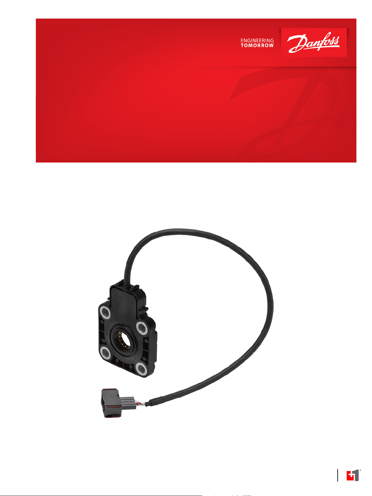
SASA Sensor
powersolutions.danfoss.com
Page 2

Technical Information
SASA Sensor
Revision history Table of revisions
Date Changed Rev
Nov 2017 Replaced SAK Adapter image on page 20 0102
March 2016 First edition 0101
2 | © Danfoss | Nov 2017 BC00000356en-US0102
Page 3

Technical Information
SASA Sensor
Contents
Sensor type SASA general
Versions, code numbers and weights for SASA sensor
SASAIIC
SASAIIC CAN message protocol..................................................................................................................................................6
SASAIIC parameter setup...............................................................................................................................................................7
SASAIIC technical data....................................................................................................................................................................8
SASAIID
SASAIID CAN message protocol..................................................................................................................................................9
SASAIID configuration protocol................................................................................................................................................12
Read data by identifier............................................................................................................................................................12
Write data by identifier...........................................................................................................................................................14
SASAIID configuration data list.................................................................................................................................................17
SASAIID technical data.................................................................................................................................................................18
Dimensions SASA sensor
SAK
Code number and weight, SAK adapter kit..........................................................................................................................20
SAK adapter kit................................................................................................................................................................................20
Installation
Wiring guidelines...........................................................................................................................................................................22
©
Danfoss | Nov 2017 BC00000356en-US0102 | 3
Page 4
Technical Information
SASA Sensor
Sensor type SASA general
The SASA sensor detects the absolute position and speed of the steering wheel. The sensor can be used
in electro-hydraulic steering systems using Danfoss OSPE, EHI, or EHPS steering valves with
programmable controller or in any other steering system where the rotation of the steering wheel must
be detected as an electronic signal.
There are two versions available of SASA sensors:
SASAIIC used for PVED-CL actuator. SASAIIC has single CAN output signal and “fail silent” concept
SASAIID used for PVED-CLS actuator and general usage. SASAIID has dual CAN output signal.
The use of SASA sensor is relevant e.g. for variable steering ratio and closed loop set-ups where steering
wheel position and steering angle have to match.
The SASA sensor also can be used for “kick out” of Auto-steering. When the steering valve is in autoguidance mode, and the driver wants to swap to manual steering, a signal from the SASA sensor will
deactivate the Auto-steering and the steering wheel movement has priority.
SASA is based on a non-contact inductive principle giving a very high resolution.
The sensor features a robust design and resists e.g. electro-magnetic radiation.
The output is a CAN signal, which makes it easy to interface to advanced vehicle controllers and to
Danfoss PVED-CLS actuators for steering valves.
The steering wheel shaft turns the rotor of the SASA sensor, and the sensor is simply mounted between
steering unit and steering column. The shaft of the steering column must be 15 mm longer when using
SASA sensor.
In cases where customers want to use the same steering column in applications with and without SASA
sensors, Danfoss offers an adapter kit type SAK to built in between column and sensor.
The SASA sensor offers the following features:
High resolution < 0.1°
•
Output CAN signal
•
High safety
•
SASAIIC: “fail silent” concept
‒
SASAIID: two output messages concept
‒
SASAIID is PLUS+1® Compliant
•
Flanged in between steering unit and column
•
Compact design
•
4 | © Danfoss | Nov 2017 BC00000356en-US0102
Page 5
Technical Information
SASA Sensor
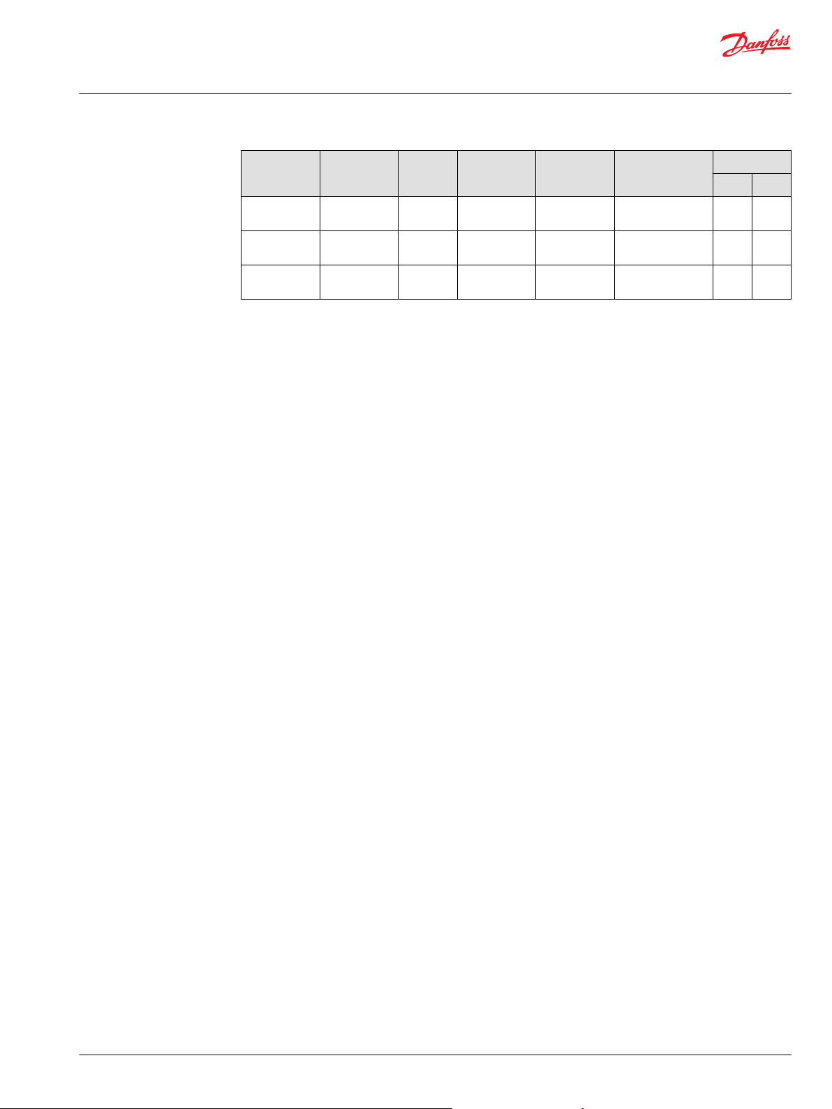
Versions, code numbers and weights for SASA sensor
Code number Type Supply
voltage
11088656 SASAIIC, CAN 9 - 32 VDCNo 500 mm AMP code no.
11099289 SASAIIC, CAN 9 - 32 VDCNo 500 mm DEUTSCH DT04-4P-
11116505 SASAIID, CAN 6 - 36 VDCNo 500 mm DEUTSCH DT04-4P-
Termination
resistor
Cable length Connector Weight
2-967059-1
CE02
CE02
kg [lb]
0.25 [0.55]
0.25 [0.55]
0.25 [0.55]
©
Danfoss | Nov 2017 BC00000356en-US0102 | 5
Page 6
Technical Information
SASA Sensor
SASAIIC
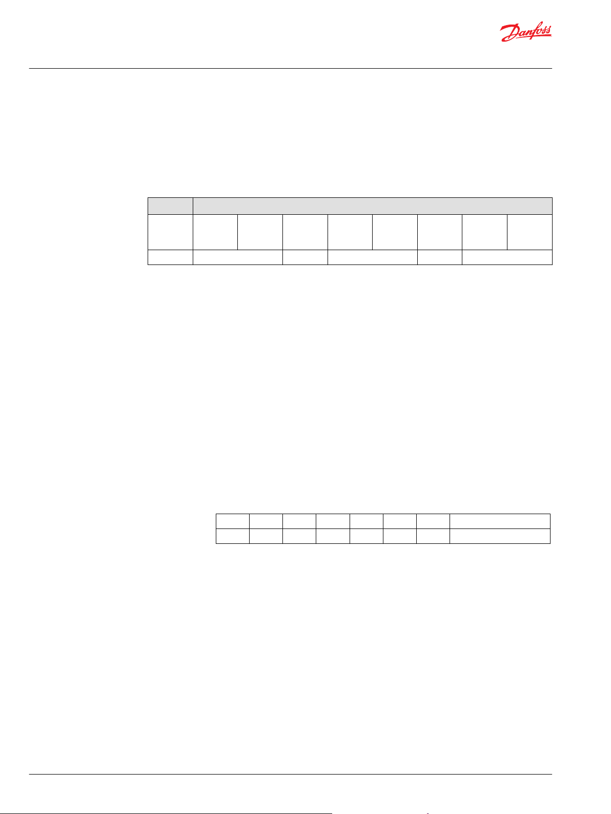
SASAIIC CAN message protocol
Interface: CAN 2.0 B
Baud rate: 125 kBaud, 250 kBaud (default), 500 kBaud
SASA returns cyclic the following CAN message every 5, 10 (default) or 20 ms.
301 h Data
0
Low byte1High byte
ID Steering angle Count Steering angle change Status CRC-16
2 3
5 6
Low byte4High byte
Low byte
Identifier 301h (11 bit)
7
High byte
Steering
angle
12 bit word (0 – 4095) relative to a 0-index point.
0 = 0 degrees
4095 = 359,912 degrees
Overflow at 4095 for CW activation shall increment 0
Underflow at 0 for CCW activation shall decrement 4095
Count Byte (0-255)
Increments 1 for each message
Steering
angle change
Difference between 2 transmitted position values in succession.
16 bit integer with 2’s complementary encoding for negative values (-32768 to 32767).
-4095 = -359,912 degrees
0 = 0 degrees
4095 = 359,912 degrees
Status
7 6 5 4 3 2 1 0
- - - - - - - Progamming mode
Programming
mode
Normal state is 1
Response with a 0 when starting the programming sequence
(See the programming sequence described below under setup
message)
CRC-16 The standard CRC16 polynomial is used (x^16+x^15+x^2+1)
6 | © Danfoss | Nov 2017 BC00000356en-US0102
Page 7
Technical Information
SASA Sensor
SASAIIC
SASAIIC parameter setup
Setup message: sensor can be programmed as shown in the CAN setup message
below.
0C0h Data
0 1 2 3 4 5 6
ID Baud rate Data rate Set 0-
index
Identifier 0C0h (11 bit)
Baud rate During the programming sequence, byte 0 is set to:
02h for 125 kBaud
•
03h for 250 kBaud (default)
•
04h for 500 kBaud
•
Data rate During the programming sequence, byte 1 is set to:
02h for 5 ms
•
03h for 10 ms (default)
•
04h for 20 ms
•
Programming
sequence
Low byte7High byte
CRC-16
Set 0-index If byte 2 is set to AAh during the programming sequence, the actual angle will be
stored as a reference value (0 degree) in persistent memory.
Programming
sequence
CRC-16 The standard CRC16 polynomial is used (x^16+x^15+x^2+1)
The following sequence is used when programming the sensor.
1. The controller unit sends a setup message where byte 4 is set to AAh and byte 5
is set to 55h.
2. The sensor answers with a 0 on the status byte (bit 0).
The control unit then sends a setup message where byte 4 is set to 0Fh and
3.
byte 5 is set to F0h.
The first and second message shall match.
4. After receiving the last message the programming takes place in the sensor if
the parameters are in the defined range, the timeout period has not been
exceeded and the CRC-16 check is correct in both messages.
5. After programming the status bit in the output message changes back from 0
to 1.
6. If the controller's second message does not come within 1 second after the
controller's first message, the programming sequence will be aborted.
©
Danfoss | Nov 2017 BC00000356en-US0102 | 7
Page 8

Technical Information
SASA Sensor
SASAIIC
SASAIIC technical data
Mechanical
Input range: Continuous 360° rotation
Rotor torque: ≤ 0.2 N•m
Expected life: > 10 million cycles
Electrical
Supply voltage: 9 - 32 V
Power consumption: <1 W
DC
Output
CAN V2.0B, (compatible to J1939)
Termination resistor: 120 ohm (optional)
Baud rate: 125, 250 or 500 kb/s
Angle: 12-bit word (0 - 4095) relative to a programmable 0-index point.
Resolution: < 0.1°
Linearity: 1% of full scale
Angle change: 16 bit integer with 2’s complementary encoding for negative values (-32768 to 32767).
Safety function
If a failure occurs, the SASA CAN transceiver will be disabled.
Environmental
Operating temperature: -30° to 85°C [-22 to 185°F]
Storage temperature: -40° to 105°C
Sealing: IP65
EMI/RFI Rating: 100 V/m
Vibration: Meets IEC 60068-2-64
Shock: Meets IEC 60068-2-27 test Ea
8 | © Danfoss | Nov 2017 BC00000356en-US0102
Page 9

Technical Information
SASA Sensor
SASAIID
SASAIID CAN message protocol
Dual CAN output
The PVED-CLS (valve controller) can interface to a SASA with redundant output. A safety function that
compares the two output messages from SASA is implemented in the PVED-CLS. There is a 180-degree
phase shift between the two angles transmitted in the messages. Steering angle 1 and steering angle 2
are sampled with a delay < 2ms. The ID1 and ID2 messages are transmitted with a delay < 5ms. It is
possible to configure the sensor to transmit cyclic 1 or 2 messages.
Interface: CAN 2.0 B
Baud rate: 250 kBaud
Transmit rate: 10, 20, 50 (default), 100, 200 ms (cyclic message transmission, 1 or 2 messages, tolerance: ±
10%)
Proprietary
B
29-bit
ID1 Steering angle 1 Steering angle velocity 1 Reserved Status CRC-16
Data
0 1 2 3 4 5 6 7
Identifier J1939 proprietary B. Programmable 29 bit message id.
ID1 = $0CFFYYXX
PGN-offset1 YY is programmable, default value is $10
Source Address XX is programmable, default value is $4D
Steering
angle 1
Data byte 0-1: Value measured by angle sensor 1 relative to the 0-index point.
16-bit integer
0 corresponds to 0 degrees
4095 corresponds to 359.912 degrees
Overflow at 4095 for CW activation shall increment 0
Underflow at 0 for CCW activation shall decrement 4095
4096 – 65534: Not available
65535:Sensor failure
Steering
angle
velocity 1
Data byte 2-3: Velocity of the rotor measured by sensor 1.
16-bit integer
0 corresponds to -300 RPM (CCW)
20480 corresponds to 0 RPM
40960 corresponds to 300 RPM (CW)
40961 – 65534: Not available
65535: Sensor failure
Reserved Data byte 4: $FF
Status Data byte 5
©
Danfoss | Nov 2017 BC00000356en-US0102 | 9
Page 10

Technical Information
SASA Sensor
SASAIID
7 6 5 4 3 2 1 0
Error Code Sequence number
Error Code Bit 4-7
$0 - Reserved
$1 - Sensor Chip Error
$2 - Steering angle failure
$3 - CAN input message failure
$4 - Power failure
$5 - CPU failure
$6 - Memory failure
$7-$D - Reserved
$E - Temperature warning
$F - No error
Sequence number Bit 0-3
Increments 1 for each message.
Valid range is $0 - $F
CRC-16 Data byte 6-7: The CRC16 polynomial 0xC86C is used to calculate a checksum for byte
0-5.
Width - 16
Init - 0x0000
Ref-In - False
Ref-Out - False
Xor-Out - 0x000
Check - 0x6774
'Check' is the CRC result for UTF-8 string “123456789”.
The above parameters conform to the Rocksoft™ Model CRC Algorithm.
Proprietary
B
29-bit
ID2 Steering angle 2 Steering angle velocity 2 Reserved Status CRC-16
Data
0 1 2 3 4 5 6 7
Identifier 2
(Optional)
J1939 proprietary B. Programmable 29 bit message id.
ID2 = $0CFFZZXX
PGN-offset2 ZZ is programmable, default value is $11
Source Address XX is programmable, default value is $4D
10 | © Danfoss | Nov 2017 BC00000356en-US0102
Page 11

Technical Information
SASA Sensor
SASAIID
Steering
angle 2
Data byte 0-1: Value measured by angle sensor 2 (with a 180 degree offset to Steering
angle 1).
16-bit integer
0 corresponds to 180 degrees
4095 corresponds to 179.912 degrees
Overflow at 4095 for CW activation shall increment 0
Underflow at 0 for CCW activation shall decrement 4095
4096 – 65534: Not available
65535:Sensor failure
Steering
angle
velocity 2
Data byte 2-3: Velocity of the rotor measured by sensor 2.
16-bit integer
0 corresponds to -300 RPM (CCW)
20480 corresponds to 0 RPM
40960 corresponds to 300 RPM (CW)
40961 – 65534: Not available
65535: Sensor failure
Reserved Data byte 4: $FF
Status Data byte 5
7 6 5 4 3 2 1 0
Error Code Sequence number
Error Code Bit 4-7
$0 - Reserved
$1 - Sensor Chip Error
$2 - Steering angle failure
$3 - CAN input message failure
$4 - Power failure
$5 - CPU failure
$6 - Memory failure
$7-$D - Reserved
$E - Temperature warning
$F - No error
Sequence number Bit 0-3
Increments 1 for each message.
Valid range is $0 - $F
CRC-16 Data byte 6-7: The CRC16 polynomial 0xC86C is used to calculate a checksum for byte
0-5.
©
Danfoss | Nov 2017 BC00000356en-US0102 | 11
Page 12

Technical Information
SASA Sensor
SASAIID
SASAIID configuration protocol
The sensor complies with the PLUS+1® Lite Diagnostic Communication Protocol – UDS.
The services to configure the sensor are:
•
•
Width - 16
Init - 0x0000
Ref-In - False
Ref-Out - False
Xor-Out - 0x000
Check - 0x6774
'Check' is the CRC result for UTF-8 string “123456789”.
The above parameters conform to the Rocksoft™ Model CRC Algorithm.
Read data by identifier on page 12
Write data by identifier on page 14
Read data by identifier
This service is used for retrieving the value of a given parameter.
29 bit CAN identifier PCI and Frame data bytes
Byte #0 Byte #1 Byte #2 Byte #3
CAN ID PCI Service ID
ID – Sub function
(MSB first)
CAN ID ID = $1BC788XX (The sensor node address XX is configurable, default value is $4D, and the
Danfoss diagnostic tester node address is $F1)
ID = $1BC78FFF (Used for broadcast requests, i.e. when the Danfoss diagnostic tester is
requesting the configuration address format)
29 bit CAN identifier
Priority Extended
data page
28 27 26 25 24 23 22
1 1 0 1 1 1 1 000 11110001 000 01001101
29 bit CAN identifier
Priority Extended
data page
28 27 26 25 24 23 22
1 1 0 1 1 1 1 000 11110001 111 11111111
Data
page
Data
page
Type of
service (TOS)
$1BC7884D
Type of
service (TOS)
$1BC78FFF
Source address Destination address
net node net node
211918
11
Source address Destination address
net node net node
211918
11
10
8
10
8
7
0
7
0
12 | © Danfoss | Nov 2017 BC00000356en-US0102
Page 13

Technical Information
SASA Sensor
SASAIID
PCI PCI = $03 (PCI type = 0, SF Data Length = 3)
Service ID SID = $22 –Read Data by Identifier
ID - Sub
See SASAIID configuration data list on page 17
function
Positive response
This message is used as positive response to a Read Data by Identifier request.
29 bit CAN identifier PCI and Frame data bytes
Byte #0 Byte #1 Byte #2 Byte #3 Byte #4 Byte #5 Byte #6 Byte #7
CAN ID PCI Service ID
ID – Sub function
(MSB first)
Value
CAN ID ID = $1BC268F1 (Here shown with the default sensor node address $4D, and the Danfoss
diagnostic tester node address $F1)
29 bit CAN identifier
Priority Extended
data page
28 27 26 25 24 23 22
1 1 0 1 1 1 1 000 01001101 000 11110001
Data
page
Type of
service (TOS)
$1BC268F1
Source address Destination address
net node net node
211918
11
10
8
7
0
PCI PCI = $0X (PCI type = 0, SF Data Length = X)
Service ID SID = $62 –Positive response ID to a Read Data by Identifier request.
ID - Sub
See SASAIID configuration data list on page 17
function
Value See SASAIID configuration data list on page 17
Negative response
This message is used as negative response to a Read Data by Identifier request.
29 bit CAN identifier PCI and Frame data bytes
Byte #0 Byte #1 Byte #2 Byte #3
CAN ID PCI Service ID
ID – Sub function
(MSB first)
CAN ID ID = $1BC268F1 (Here shown with the default sensor node address $4D, and the Danfoss
diagnostic tester node address $F1)
©
Danfoss | Nov 2017 BC00000356en-US0102 | 13
Page 14

Technical Information
SASA Sensor
SASAIID
29 bit CAN identifier
Priority Extended
data page
28 27 26 25 24 23 22
1 1 0 1 1 1 1 000 01001101 000 11110001
Data
page
Type of service
(TOS)
$1BC268F1
PCI PCI = $03 (PCI type = 0, SF Data Length = 3)
Service ID SID = $7F –Negative response ID
Source address Destination address
net node net node
211918
11
10
8
7
0
ID - Sub
$22XX (For XX, see the following table)
function
Byte 2 Error message Error cause Service Tool response
$13 Incorrect
Message Length
Or Invalid
Format
$22 Conditions Not
Correct
$31 Request Out Of
Range
$33 Security Access
Denied
$78 Response
pending
The length of the message is wrong Resend correct command
This code shall be returned if operating
conditions of the server for performing
the required action are not met.
This code shall be sent if:
1. none of the requested data
identifier values are supported by
the device
2. the client exceeded the maximum
number of data identifiers allowed
to be requested at a time
This code shall be sent if at least one of
the data identifiers is secured and the
server is not in an unlocked state
Routine needs more time Extend P2_CAN_Server_max
Write data by identifier
This service is used for writing configuration data.
Resend command later
Resend with correct/fewer
IDs
Perform security access
routine
to P2*_CAN_Server_max
29 bit CAN identifier PCI and Frame data bytes
Byte #0 Byte #1 Byte #2 Byte #3 Byte #4 Byte #5 Byte #6 Byte #7
CAN ID PCI Service ID
ID – Sub function
(MSB first)
Value
CAN ID ID = $1BC788XX (The sensor node address XX is configurable, default value is $4D, and the
Danfoss diagnostic tester node address is $F1)
14 | © Danfoss | Nov 2017 BC00000356en-US0102
Page 15

Technical Information
SASA Sensor
SASAIID
29 bit CAN identifier
Priority Extended
data page
28 27 26 25 24 23 22
1 1 0 1 1 1 1 000 11110001 000 01001101
Data
page
Type of
service (TOS)
$1BC7884D
PCI PCI = $0X (PCI type = 0, SF Data Length = X)
Service ID SID = $2E –Write Data by Identifier
Source address Destination address
net node net node
211918
11
10
8
7
0
ID - Sub
See SASAIID configuration data list on page 17
function
Value See SASAIID configuration data list on page 17
Positive response
This message is used as positive response to a Write Data by Identifier request.
29 bit CAN identifier PCI and Frame data bytes
Byte #0 Byte #1 Byte #2 Byte #3
CAN ID PCI Service ID
ID – Sub function
(MSB first)
CAN ID ID = $1BC268F1 (Here shown with the default sensor node address $4D, and the Danfoss
diagnostic tester node address $F1)
29 bit CAN identifier
Priority Extended
data page
28 27 26 25 24 23 22
1 1 0 1 1 1 1 000 01001101 000 11110001
Data
page
Type of
service (TOS)
$1BC268F1
Source address Destination address
net node net node
211918
11
10
8
7
0
PCI PCI = $03 (PCI type = 0, SF Data Length = 3)
Service ID SID = $6E –Positive response ID to a Write Data by Identifier request.
ID - Sub
See SASAIID configuration data list on page 17
function
Negative response
This message is used as negative response to a Write Data by Identifier request.
29 bit CAN identifier PCI and Frame data bytes
Byte #0 Byte #1 Byte #2 Byte #3
CAN ID PCI Service ID
©
Danfoss | Nov 2017 BC00000356en-US0102 | 15
ID – Sub function
(MSB first)
Page 16

Technical Information
SASA Sensor
SASAIID
CAN ID ID = $1BC268F1 (Here shown with the default sensor node address $4D, and the Danfoss
diagnostic tester node address $F1)
29 bit CAN identifier
Priority Extended
data page
28 27 26 25 24 23 22
1 1 0 1 1 1 1 000 01001101 000 11110001
Data
page
Type of service
(TOS)
$1BC268F1
Source address Destination address
net node net node
211918
11
10
8
7
0
PCI PCI = $03 (PCI type = 0, SF Data Length = 3)
Service ID SID = $7F –Negative response ID
ID - Sub
function
$2EXX (For XX, see the following table)
Byte 2 Error message Error cause Service Tool response
$13 Incorrect Message
Length Or Invalid
Format
$22 Conditions Not
Correct
$31 Request Out Of
Range
$33 Security Access
Denied
$72 General
Programming
Failure
$78 Response pending Routine needs more time Extend
The length of the message is wrong Resend correct command
This code shall be returned if
operating conditions of the server for
performing the required action are
not met.
This code shall be sent if:
1. none of the requested data
identifier values are supported by
the device
2. the client exceeded the maximum
number of data identifiers allowed
to be requested at a time
This code shall be sent if at least one
of the data identifiers is secured and
the server is not in an unlocked state
This return code shall be sent if the
server detects an error when writing
to a memory location
Resend command later
Resend with correct ID /
data
Perform security access
routine
Resend command
P2_CAN_Server_max to
P2*_CAN_Server_max
16 | © Danfoss | Nov 2017 BC00000356en-US0102
Page 17

Technical Information
SASA Sensor
SASAIID
SASAIID configuration data list
This is a list of all configurable parameters.
Identifier Name Access Value/Range Default
$0101 Node Address R/W $01 – $FD $4D
$0102 Output mode R/W
$0103 Message transmission rate (CAN mode) R/W
$0104 Zero-index W $AA – just a trigger value $00
$0109 Temperature R $XX (8 bit integer),[°C]
$010A PGN-offset1 R/W $01 – $FF $10
$010B PGN-offset2 R/W $01 – $FF $11
$0201 - $021F Reserved for supplier
$F010 Address Format R $A5
$F1FA Diagnostic File ID Part A R $350A706F (MSB first)
$F1FB Diagnostic File ID Part B R $0D164B57 (MSB first)
$F1FC Diagnostic File ID Part C R $BC59E069 (MSB first)
$F1FD Diagnostic File ID Part D R $4ACFFEE7 (MSB first)
$F193 Hardware version R XXXXXXXX (4 characters)
$F195 Software version R XXXXXXXX (4 characters)
$F18C Serial Number R $XXXXXXXX (32 bit integer, MSB first)
$F18B Manufacturing date R YY,MM,DD in BCD
$01 (Single message)
$02 (Dual message)
$03 (10 ms)
$04 (20 ms)
$05 (50 ms)
$06 (100 ms)
$07 (200 ms)
$02
$05
©
Danfoss | Nov 2017 BC00000356en-US0102 | 17
Page 18

Technical Information
SASA Sensor
SASAIID
SASAIID technical data
Mechanical
Input range: Continuous 360° rotation
Rotor torque: ≤ 0.2 N•m
Expected life: > 10 million cycles
Electrical
Supply voltage: 6 - 36 V
Power consumption: <2 W
DC
Output
CAN V2.0B, (compatible to J1939)
Termination resistor: 120 ohm (optional)
Baud rate: 250 kb/s
Angle: 12-bit word (0 - 4095) relative to a programmable 0-index point.
Resolution: < 0.1°
Linearity: <1% of full scale
Angle change: 16 bit integer. Values: primary message from 0–40960. Redundant message: the same
but with 20480 offset.
Safety function
Dual CAN output signal (the CAN signals are supervised by the PVED-CLS actuator or alternative external
safety controller).
However, the SASAIID has built in these safety and monitoring functions:
•
Sensor chip diagnostics
•
Steering angle cross-check
•
MCU heartbeat check: the two microcontrollers check each other's aliveness
•
Power-on memory check
Environmental
Operating temperature: -40° to 105°C [-40° to 221°F]
Storage temperature: -55° to 105°C [-67° to 221°F]
Sealing: IP65
EMI/RFI Rating: 150 V/m
Vibration: Meets IEC 60068-2-64
Shock: Meets IEC 60068-2-27 test Ea
18 | © Danfoss | Nov 2017 BC00000356en-US0102
Page 19

∅44.5 [∅1.75]
4x ∅10.8 [4x ∅0.43]
∅
82 ±0.3
[
∅
3.23 ±0.01]
∅44.4 [∅1.75]
83 [3.27]
41.5 [1.63]
118 [4.65]
76.5 [3.01]
Label
(Code No.)
3 [0.12]
15.6
[0.61]
8.6 [0.34]
2.8 [0.11]
P301 221
Technical Information
SASA Sensor
Dimensions SASA sensor
©
Danfoss | Nov 2017 BC00000356en-US0102 | 19
Page 20

1
2
2.8
12
41.5
14 min.
45°
4
.
4
4
-0.1
4
2
5
.
4
2
3
4x ø11
83
R15
ø82±0.3
Technical Information
SASA Sensor
SAK
Code number and weight, SAK adapter kit
Code number Weight
150Z6000 0.8
SAK adapter kit
1. Flexible teeth, 12 pieces to interact with splines on steering column
2. Cable, 500 mm with connector. See “Code numbers” for type of connector
kg
[lb]
[1.76]
1. Distance plate
2. Shaft
20 | © Danfoss | Nov 2017 BC00000356en-US0102
Page 21

min. 22.4 [0.88]
17 [0.67]
15.3
[0.60]
1 2
4 [0.16]
P301 223
C
27.5
[1.08]
4321
4 [0.16]
min. 7.1 [0.28]
P301 222
Technical Information
SASA Sensor
Installation
SASA has to be mounted between steering column and steering unit (OSP) with 4 bolts max 30 N•m
[265.5 lbf•in]. Shaft in column must be 15 mm [0.59 in] longer when using SASA.
Assembly: SASA sensor and OSP steering unit
1. SASA sensor
2. OSP steering unit
Caution
Make sure that the spline profile of the SASA sensor is aligned to the spline profile of the steering column
shaft. A safe method of assembly is to place SASA sensor on the steering column spline shaft first – and
not opposite! In case of using force, there is a risk of bending the spline profile of SASA sensor.
For use of original steering column, use adapter kit type SAK, see sketch below.
Assembly: SAK adapter kit, SASA sensor and OSP steering unit
1. Shaft of SAK adapter kit
2. Distance plate of SAK adapter kit
3. SASA sensor
4. OSP steering unit
©
Danfoss | Nov 2017 BC00000356en-US0102 | 21
Page 22

Technical Information
SASA Sensor
Installation
Wiring guidelines
•
Protect wires from mechanical abuse, run wires in flexible metal or plastic conduits.
•
Use 85˚ C (185˚ F) wire with abrasion resistant insulation and 105˚ C (221˚ F) wire should be
considered near hot surfaces.
•
Use a wire size that is appropriate for the module connector.
•
Separate high current wires such as solenoids, lights, alternators or fuel pumps from sensor and other
noise-sensitive input wires.
•
Run wires along the inside of, or close to, metal machine surfaces where possible, this simulates a
shield which will minimize the effects of EMI/RFI radiation.
•
Do not run wires near sharp metal corners, consider running wires through a grommet when
rounding a corner.
•
Do not run wires near hot machine members.
•
Provide strain relief for all wires.
•
Avoid running wires near moving or vibrating components.
•
Avoid long, unsupported wire spans.
•
Ground electronic modules to a dedicated conductor of sufficient size that is connected to the
battery (-).
•
Power the sensors and valve drive circuits by their dedicated wired power sources and ground
returns.
•
Twist sensor lines about one turn every 10 cm (4 in).
•
Use wire harness anchors that will allow wires to float with respect to the machine rather than rigid
anchors.
22 | © Danfoss | Nov 2017 BC00000356en-US0102
Page 23

Technical Information
SASA Sensor
©
Danfoss | Nov 2017 BC00000356en-US0102 | 23
Page 24

Danfoss
Power Solutions GmbH & Co. OHG
Krokamp 35
D-24539 Neumünster, Germany
Phone: +49 4321 871 0
Danfoss
Power Solutions ApS
Nordborgvej 81
DK-6430 Nordborg, Denmark
Phone: +45 7488 2222
Danfoss
Power Solutions (US) Company
2800 East 13th Street
Ames, IA 50010, USA
Phone: +1 515 239 6000
Danfoss
Power Solutions Trading
(Shanghai) Co., Ltd.
Building #22, No. 1000 Jin Hai Rd
Jin Qiao, Pudong New District
Shanghai, China 201206
Phone: +86 21 3418 5200
Products we offer:
Comatrol
www.comatrol.com
Turolla
www.turollaocg.com
Hydro-Gear
www.hydro-gear.com
Daikin-Sauer-Danfoss
www.daikin-sauer-danfoss.com
Bent Axis Motors
•
Closed Circuit Axial Piston
•
Pumps and Motors
Displays
•
Electrohydraulic Power
•
Steering
Electrohydraulics
•
Hydraulic Power Steering
•
Integrated Systems
•
Joysticks and Control
•
Handles
Microcontrollers and
•
Software
Open Circuit Axial Piston
•
Pumps
Orbital Motors
•
PLUS+1® GUIDE
•
Proportional Valves
•
Sensors
•
Steering
•
Transit Mixer Drives
•
Danfoss Power Solutions is a global manufacturer and supplier of high-quality hydraulic and
electronic components. We specialize in providing state-of-the-art technology and solutions
that excel in the harsh operating conditions of the mobile off-highway market. Building on
our extensive applications expertise, we work closely with our customers to ensure
exceptional performance for a broad range of off-highway vehicles.
We help OEMs around the world speed up system development, reduce costs and bring
vehicles to market faster.
Danfoss – Your Strongest Partner in Mobile Hydraulics.
Go to www.powersolutions.danfoss.com for further product information.
Wherever off-highway vehicles are at work, so is Danfoss. We offer expert worldwide support
for our customers, ensuring the best possible solutions for outstanding performance. And
with an extensive network of Global Service Partners, we also provide comprehensive global
service for all of our components.
Please contact the Danfoss Power Solution representative nearest you.
Local address:
Danfoss can accept no responsibility for possible errors in catalogues, brochures and other printed material. Danfoss reserves the right to alter its products without notice. This also applies to products
already on order provided that such alterations can be made without changes being necessary in specifications already agreed.
All trademarks in this material are property of the respective companies. Danfoss and the Danfoss logotype are trademarks of Danfoss A/S. All rights reserved.
©
Danfoss | Nov 2017 BC00000356en-US0102
 Loading...