

Page 1

Installation Instruction
Danfoss RX-C Roof and
Gutter De-Icing System
Page 2

Installation Instruction
Danfoss RX-C Roof and Gutter De-Icing System
Table of contents
1 Overview . . . . . . . . . . . . . . . . . . . . . . . . . . . . . . . . . . . . . . . . . . . . . . . . 3
2 Safety . . . . . . . . . . . . . . . . . . . . . . . . . . . . . . . . . . . . . . . . . . . . . . . . . . 3
3 Certifications / Approvals . . . . . . . . . . . . . . . . . . . . . . . . . . . . . . . . . . . . . 4
4 Technical data. . . . . . . . . . . . . . . . . . . . . . . . . . . . . . . . . . . . . . . . . . . . . 4
5 Personnel requirements . . . . . . . . . . . . . . . . . . . . . . . . . . . . . . . . . . . . . . 4
6 System design. . . . . . . . . . . . . . . . . . . . . . . . . . . . . . . . . . . . . . . . . . . . . 5
7 Power connection components . . . . . . . . . . . . . . . . . . . . . . . . . . . . . . . . . 6
8 End-termination . . . . . . . . . . . . . . . . . . . . . . . . . . . . . . . . . . . . . . . . . . . 6
9 Accessories . . . . . . . . . . . . . . . . . . . . . . . . . . . . . . . . . . . . . . . . . . . . . . 6
10 Trace heater installation . . . . . . . . . . . . . . . . . . . . . . . . . . . . . . . . . . . . . . 7
Preparation . . . . . . . . . . . . . . . . . . . . . . . . . . . . . . . . . . . . . . . . . . . . . . . . . 7
Determination of the trace heater length . . . . . . . . . . . . . . . . . . . . . . . . . . . . . . 7
Number of heating circuits . . . . . . . . . . . . . . . . . . . . . . . . . . . . . . . . . . . . . . 10
Required tools / equipment . . . . . . . . . . . . . . . . . . . . . . . . . . . . . . . . . . . . . . 11
Unrolling the trace heater . . . . . . . . . . . . . . . . . . . . . . . . . . . . . . . . . . . . . . . 12
Trace heater fixation on roofs . . . . . . . . . . . . . . . . . . . . . . . . . . . . . . . . . . . . . 13
Placement of connection / splice kits . . . . . . . . . . . . . . . . . . . . . . . . . . . . . . . . 14
Application of warning labels . . . . . . . . . . . . . . . . . . . . . . . . . . . . . . . . . . . . . 14
11 Tests and putting into operation . . . . . . . . . . . . . . . . . . . . . . . . . . . . . . . 14
Measurement of the insulation resistance . . . . . . . . . . . . . . . . . . . . . . . . . . . . . 14
Acceptance test and acceptance test report. . . . . . . . . . . . . . . . . . . . . . . . . . . . 15
Putting into operation . . . . . . . . . . . . . . . . . . . . . . . . . . . . . . . . . . . . . . . . . 16
12 Operation . . . . . . . . . . . . . . . . . . . . . . . . . . . . . . . . . . . . . . . . . . . . . . 16
System documentation. . . . . . . . . . . . . . . . . . . . . . . . . . . . . . . . . . . . . . . . . 16
13 Maintenance . . . . . . . . . . . . . . . . . . . . . . . . . . . . . . . . . . . . . . . . . . . . 17
Visual and functional inspection . . . . . . . . . . . . . . . . . . . . . . . . . . . . . . . . . . . 17
Electrical inspection . . . . . . . . . . . . . . . . . . . . . . . . . . . . . . . . . . . . . . . . . . . 17
Inspection intervals . . . . . . . . . . . . . . . . . . . . . . . . . . . . . . . . . . . . . . . . . . . 17
Personnel training courses. . . . . . . . . . . . . . . . . . . . . . . . . . . . . . . . . . . . . . . 17
Repairwork on roofs and gutters . . . . . . . . . . . . . . . . . . . . . . . . . . . . . . . . . . . 17
14 Troubleshooting . . . . . . . . . . . . . . . . . . . . . . . . . . . . . . . . . . . . . . . . . . 18
15 Acceptance report . . . . . . . . . . . . . . . . . . . . . . . . . . . . . . . . . . . . . . . . . 19
16 Limited product warranty . . . . . . . . . . . . . . . . . . . . . . . . . . . . . . . . . . . . 20
Scope . . . . . . . . . . . . . . . . . . . . . . . . . . . . . . . . . . . . . . . . . . . . . . . . . . . . 20
Conditions . . . . . . . . . . . . . . . . . . . . . . . . . . . . . . . . . . . . . . . . . . . . . . . . . 20
How to claim the warranty. . . . . . . . . . . . . . . . . . . . . . . . . . . . . . . . . . . . . . . 20
Applicability of implied warranties, state or provincial laws . . . . . . . . . . . . . . . . . . 20
17 Safety . . . . . . . . . . . . . . . . . . . . . . . . . . . . . . . . . . . . . . . . . . . . . . . . . 21
18 Sécurité et avertissements . . . . . . . . . . . . . . . . . . . . . . . . . . . . . . . . . . . 22
2 | © Danfoss | 2019.11
VIKZE222
Page 3

Installation Instruction
Danfoss RX-C Roof and Gutter De-Icing System
1 Overview
This manual introduces the installation and operation of trace heating circuits using the following
self-regulating trace heaters:
• Danfoss RX-C Roof and Gutter De-Icing System
The self-regulating trace heater features a temperature-dependent resistive element between two
parallel copper conductors, that regulates and limits the heat output of the trace heater according to
the ambient temperature. If the ambient temperature rises, the power output of the trace heater is
reduced. This self-regulating property prevents overheating which would cause damage to the trace
heater. Even crossing or overlapping with other trace heaters (or other portions of the same trace heater) are possible as given from table on page 13.
The heating system is set up as a fixed equipment heating system for roof and gutter de-icing in ordinary locations. Thanks to the parallel design the trace heater can be cut and installed to any required
length.
Multiple options for connection, splicing and end-termination of the heating circuit are available to
meet the individual requirements on site. A large variety of accessories allows for easy customization
and extensibility.
2 Safety
For safe installation and operation of the RX-C trace heater the technical requirements and instructions
given in this manual must be followed.
WARNING:
Risk of fire or electrical shock. Follow these guidelines to avoid personal injury or material damage.
• All electrical systems and installations must comply with Danfoss requirements and be installed in
accordance with the relevant electrical codes and any other applicable national and local codes.
• The US and Canadian electrical codes require ground fault protection to be provided for all trace
heating circuits.
• Install the connection system and trace heaters carefully.
• Use the trace heater and connection system in accordance with the intended purpose and strictly
comply with the operational data specified in section Technical Data.
• The bending radius of the trace heater must be at least 1” (25 mm). Do not bend on the narrow axis.
• Any defective component of the kit must be replaced before installation.
• To avoid short circuits, do not connect the trace heater bus wires together.
• Keep all components and the trace heaters dry before and during installation.
• Beware of hot surfaces when using the heat gun.
• Keep these instructions for future reference. If applicable, leave them with the end user.
• De-energize before installation or servicing.
• Use only original Danfoss accessories.
VIKZE222
© Danfoss | 2019.11 | 3
Page 4

Installation Instruction
Danfoss RX-C Roof and Gutter De-Icing System
3 Certifications / Approvals
Danfoss RX-C self-regulating trace heater for roof and gutter de-icing.
4 Technical data
Ambient temperature range -67 °F to 185 °F / -55 °C to +85 °C
Operation temperatures -40 °F to 149 °F / -40 °C to +65 °C
Voltage 110 to 120 VAC / 208 to 254 VAC
Heat output 5 W/ft @ 50 °F / 15 W/m @ 10 °C
Resistance Grounding braid: < 18.2 Ω/km
Dimensions
polyolefin outer jacket
Minimum bending radius 1” (25 mm)
0.46” x 0.23” (11.6 x 5.8 mm)
Do not bend on the narrow axis.
5 Personnel requirements
The personnel executing installation and maintenance tasks must have acquired the skills and specialized knowledge relating to the types of protection and types of devices concerned. At least, the
personnel must have:
• a general understanding of the relevant electrical engineering (Qualified Electrician)
• a working knowledge and understanding of the relevant standards for electrical installations in
general and trace heating in particular
• a basic knowledge of quality assurance, including the principles of auditing documentation, traceability of measurements and calibration of measurement instruments.
4 | © Danfoss | 2019.11
VIKZE222
Page 5

Installation Instruction
Danfoss RX-C Roof and Gutter De-Icing System
6 System design
A heating circuit with self-regulating trace heaters usually consists of:
• Power supply cable connection;
• End-termination;
• Control and monitoring units (optional).
The following figure shows a sample trace heating system including typical components:
junction box trace heater roof clip
end-termination
The following pages list all compatible components for the RX-C heating system for roof and gutter
applications. The respective installation instructions are included in the scope of delivery.
VIKZE222
© Danfoss | 2019.11 | 5
Page 6

Installation Instruction
Danfoss RX-C Roof and Gutter De-Icing System
7 Power connection components
The following components can be used for power connection with the RX-C trace heater:
Power connection kit
Catalog No.: 088L0023
Cable to Junction Box with
½” NPT cable gland
For connection of selfregulating trace heaters in
a junction box. Electrical
insulation is ensured by heat
shrink tubes.
Junction is not included.
Includes end-temination.
8 End-termination
The following components can be used for trace heater splices / junctions with the RX-C trace heater:
End-termination –
Connecto NA B-E Silicone end
seal for insulation of the end
of the trace heater.
Includes 5 x endcap and 2 x
Silicone adhesive.
End-termination
Catalog No.: 088L0767
Catalog No.: 088L1457
6 | © Danfoss | 2019.11
Heat shrinkable end cap for
insulation of the end of the
trace heater.
Includes 5 kits.
VIKZE222
Page 7

Installation Instruction
Danfoss RX-C Roof and Gutter De-Icing System
9 Accessories
The following original Danfoss accessories are available for the Danfoss RX-C Roof and Gutter De-Icing
System applications:
NOTICE: To ensure compliance with the existing technical regulations, use only original accessories
from Danfoss. The use of original accessories from Danfoss is a precondition for the consideration of
any warranty claims.
Downspout Edge Protection
Plate
Spaceclip for self-limiting
cables. One per kit.
RX-C Roof Clips
The clips are designed to
secure the cables to asphalt
shingles, metal seam roofs,
and gutters. 50 per bag.
Catalog No.: 088L3002
Catalog No.: 088L3001
10 Trace heater installation
Preparation
Before installing any electric trace heating, the person installing must check if the trace heating has
been designed and planned correctly. It is particularly essential to verify the following points:
• complete project planning documentation, operating instructions and installation instructions.
• correct selection of the trace heater and accessories with respect to:
· calculation of heat losses;
· min. permissible start-up temperature;
· max. permissible operating temperature;
· max. permissible ambient temperature.
Before installing, make sure that the roof covering, gutters and downspouts are properly installed.
Determination of the trace heater length
The total required trace heater length is determined by the length of the roof, the number of valleys
and dimensions of gutters and downspouts.
© Danfoss | 2019.11 | 7VIKZE222
Page 8

Installation Instruction
Danfoss RX-C Roof and Gutter De-Icing System
Step 1
Determine the required trace heater length for the roof.
Standard sloped roofs Standing seam roofs
Roof overhang Roof multiplier Roof overhang Loop height
12 in (30 cm) 2 12 in (30 cm) 18 in (45 cm)
24 in (60 cm) 3 24 in (60 cm) 30 in (75 cm)
36 in (90 cm) 4 36 in (90 cm) 42 in (105 cm)
length for roofs = roof edge length * roof
multiplier
length for roofs = roof edge length + loop height
* number of seams
Step 2
Determine the required trace heater length for valleys.
Snow and ice often accumulate in valleys. The trace heater should be routed up and down the valley to
maintain a clear path of melted snow. Add approximately 6 ft. (180 cm) of heating cable for each valley.
length for valleys = number of valleys * 6 ft. (180 cm)
8 | © Danfoss | 2019.11
VIKZE222
Page 9

Installation Instruction
Danfoss RX-C Roof and Gutter De-Icing System
Step 3
Determine the required trace heater length for gutters.
To allow melted snow and ice to be evacuated, the trace heater must be routed through the gutters. In
large gutters, multiple trace heaters are necessary.
Gutter width Number of trace heaters
< 4 ¾” (12 cm) 1
< 9 ½” in (24 cm) 2
> 9 ½” in (24 cm) 3 or more
length for gutters = gutter length
* number of trace heaters
Separate cable in gutter using clips, 3” separation.
Step 4
Determine the required trace heater length for downspouts.
To allow melted snow and ice to be evacuated, the trace heater must be routed
through downspouts (down and up).
NOTICE: Always use a Downspout protector plate when entering and exiting
the downspouts.
length of all downspouts * 2
VIKZE222
length for downspouts =
© Danfoss | 2019.11 | 9
Page 10

Installation Instruction
Danfoss RX-C Roof and Gutter De-Icing System
Step 5
Determine the total required trace heater length.
Add the calculated lengths of all sections together to obtain the total required trace heater length.
Section Calculation method Cable length
standard sloped roofs:
roof edge length * roof multiplier
Roof
Valleys number of valleys * 6 ft. (180 cm)
Gutters gutter length * number of trace heaters
Downspouts length of all downspouts * 2
TOTAL REQUIRED LENGTH _________________
standing seam roofs:
roof edge length + loop height *
number of seams
Number of heating circuits
The following table shows the maximum circuit lengths in ft (m) for the Danfoss RX-C Roof and Gutter
De-Icing System for different installation locations with standard circuit breaker amperages. Breaker
sizing should be based on the National Electrical Code, Canadian Electrical Code or any other local or
applicable code. Use only circuit breakers with type C tripping characteristics.
10 | © Danfoss | 2019.11
VIKZE222
Page 11

Installation Instruction
WARNING:
Danfoss RX-C Roof and Gutter De-Icing System
Risk of fire, electrical shock or dysfunction. Observe the maximum amperage of all components of the
trace heating circuit. If the required trace heater length exceeds the maximum heating circuit length
you must install multiple heating circuits.
Power output
Location
On roofs and valleys
and in gutters and
downspouts
Start-up
temp.
°F (°C)
ice water 131 (40) 131 (40) 131 (40) 230 (70) 230 (70) 230 (70) 262 (80) 262 (80) 262 (80)
Operating Voltage: 120 Vac Operating Voltage: 208 Vac Operating Voltage: 240 Vac
20 A 30 A 40 A 20 A 30 A 40 A 20 A 30 A 40 A
Maximum heating circuit length in ft. (m) based on circuit breaker sizing
NOTICE: Automatic circuit breaker has to be “C” tripping characteristic.
Required tools / equipment
The following tools are required for installation of the Danfoss RX-C Roof and Gutter De-Icing System:
• Hammer
• Cross-head screwdriver
The following protective equipment is required:
• Safety gloves
Recommended adhesive for metal roofs:
• Roof Clip Glue RX-C Roof Clip Adhesive (10.3 fl. oz. tube)
VIKZE222
© Danfoss | 2019.11 | 11
Page 12

Installation Instruction
Danfoss RX-C Roof and Gutter De-Icing System
Unrolling the trace heater
WARNING:
Risk of short cuts and/or material damage. Keep the trace heater ends dry before and during installation. Observe the trace heater’s installation instructions.
Unroll the required trace heater in a straight line and cut to the correct length. Cut off the trace heater
ensuring a straight cut.
Do not bend or pinch the trace heater, or pull it over sharp edges.
12 | © Danfoss | 2019.11
VIKZE222
Page 13

Installation Instruction
Danfoss RX-C Roof and Gutter De-Icing System
Trace heater fixation on roofs
Attach the clip to the roof as follows:
For metal roofs use adhesive
(for adhesive selection refer to page 11):
Attach the trace heater to the clip using UV-resistant cable ties.
Standard sloped roofs Standing seam roofs
On standard sloped roofs, locate the trace heater
in a triangle pattern according to the following
table:
Roof overhang Loop height Loop spacing Roof overhang Loop height Loop spacing
12 in (30 cm) 18 in (45 cm) 24 in (60 cm) 12 in (30 cm) 18 in (45 cm) on every seam
24 in (60 cm) 30 in (75 cm) 24 in (60 cm) 24 in (60 cm) 30 in (75 cm) on every seam
36 in (90 cm) 42 in (105 cm) 24 in (60 cm) 36 in (90 cm) 42 in (105 cm) on every seam
On sloped roofes with standing seams, run the
trace heater along the seams according to the
following table:
NOTICE: The bending radius of the trace heater
must be at least 1” (25 mm); do not bend in an
upright position.
Use as many roof clips as necessary to provide
proper fixation of the trace heater.
VIKZE222
NOTICE: The bending radius of the trace heater
must be at least 1” (25 mm); do not bend in an
upright position.
Use as many roof clips as necessary to provide
proper fixation of the trace heater.
© Danfoss | 2019.11 | 13
Page 14
Installation Instruction
Danfoss RX-C Roof and Gutter De-Icing System
Placement of connection / splice kits
All connection / splice kits must be placed in a dry place, e.g.:
• under roof overhangs
• under gutters
• on the edge of the roof gutter
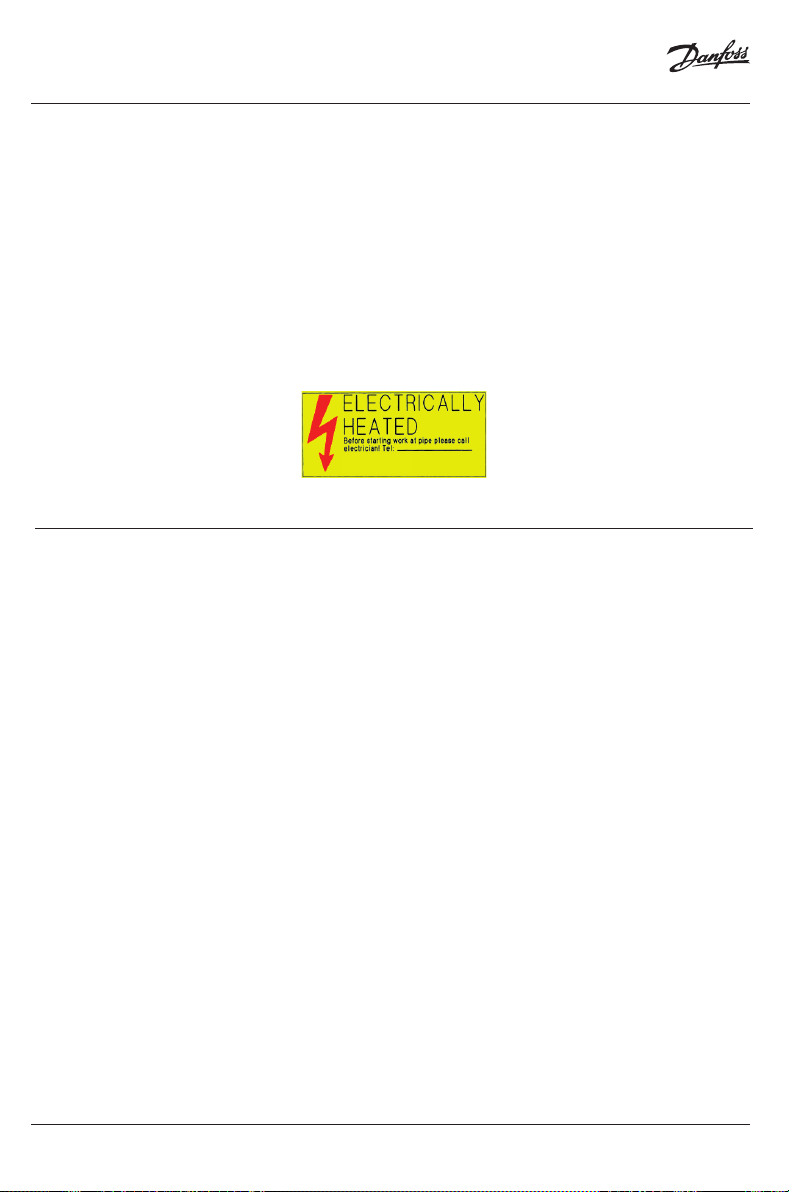
Application of warning labels
Apply electrical warning labels on a clearly visible place.
11 Tests and putting into operation
Measurement of the insulation resistance
The measurement of the insulation resistance is used to determine damage to the trace heater and
possible installation faults. It must be carried out at the following times:
• Preliminary test (shortly before beginning installation of the trace heater on the construction site;
refer to section Acceptance Report on page 19)
• Acceptance test (after the complete installation of the heating circuit or fitting of the thermal insulation; refer to section Acceptance Report on page 19)
• Final inspection (immediately after completion of work on the thermal insulation)
• Upon commissioning
• Before switching on the installation
14 | © Danfoss | 2019.11
VIKZE222
Page 15
Installation Instruction
Danfoss RX-C Roof and Gutter De-Icing System
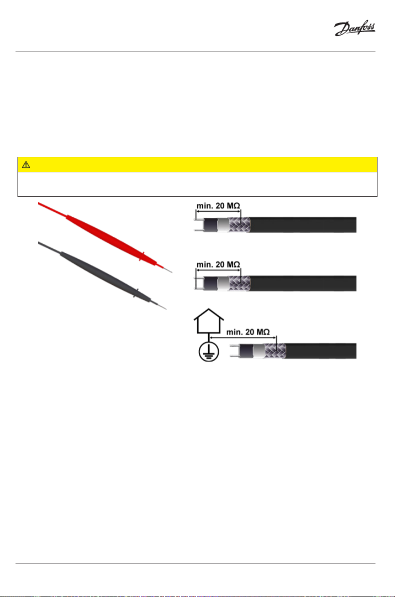
To do the measurement, proceed as follows:
• Use an isolation tester with a minimum testing voltage of 500 VDC and a maximum testing voltage
of 2500 VDC. Recommended testing voltage: 1500 VDC. Required insulation resistance: > 20 MΩ.
• Measure the resistance between each bus wire of the trace heater and the grounding braid.
• Measure the resistance between the grounding braid and the earth potential (for this measurement
the heating circuit must not be grounded yet).
WARNING:
Risk of fire or electrical shock. If the insulation resistance is insufficient you must fix the heating circuit
before putting it into operation.
NOTICE: The heating circuit must not be grounded.
Acceptance test and acceptance test report
After completion of the installation work (before fitting the thermal insulation) each heating circuit
must be accepted, if possible in the presence of the client.
All further tests must also be documented in an acceptance test report (refer to section Acceptance
Report on page 19).
NOTICE: Claims under warranty will not be considered if the acceptance report is not filled in
completely.
After completion of work on the thermal insulation final inspection and acceptance of the individual
heating circuits is recommended. Usually, this is the task of the client or the final customer (final inspection).
VIKZE222
© Danfoss | 2019.11 | 15
Page 16

Installation Instruction
Danfoss RX-C Roof and Gutter De-Icing System
Putting into operation
Each heat tracing system can only be put into operation if the following conditions are fulfilled:
• The acceptance test reports for each heating circuit are available and the perfect state of the trace
heating system has been confirmed.
• All components of the heating circuit are completely installed and are in working order.
• It has been ensured that the heating circuit is operated in conformance with the technical data
specified by Danfoss.
12 Operation
During operation of the electric trace heating system you must ensure that all components of the
system are operated within the operating data specified by Danfoss.
This applies particularly to observation of the maximum temperature. Operation within these operating data is a precondition for possible later warranty claims.
System documentation
Complete documentation must be carried out for each system, from the project planning stage,
through installation and putting into operation up to periodic maintenance of the trace heating
system.
This documentation should include the following:
• Project planning documents
• Manuals of all of the components of the heating system
• Heat loss calculation
• Selection of the trace heater
• Layout plans with division of heating circuits
• Circuit diagrams
• Acceptance reports
• Reports on repair work and any operations carried out on the de-icing system
• Inspection reports
16 | © Danfoss | 2019.11
VIKZE222
Page 17

Installation Instruction
Danfoss RX-C Roof and Gutter De-Icing System
13 Maintenance
Visual and functional inspection
Remove any deposit of leaves, mud etc. from gutters and downspouts.
Regulary check the trace heater for possible damage.
Damaged trace heaters must be replaced.
Parts subject to wear must be replaced (e.g. seals, locking plates etc).
Check junction boxes, splices and end-terminations for corrosion and possible mechanical damage.
Make sure that all enclosure covers are properly in place.
If present, check the temperature regulator (Thermostat/automatic sensing system) connecting cables and capillary tube systems for damage and that their installation is protected against mechanical
damage.
Electrical inspection
Measurement of the insulation resistance should be seen as a permanent part of regular maintenance.
For instructions on how to perform the test refer to section Measurement of the insulation resistance
on page 14.
Inspection intervals
Inspections should be carried out annually before the heating period begins.
Personnel training courses
Regular maintenance should be carried out by trained, experienced maintenance personnel.
Repairwork on roofs and gutters
Make sure that all power circuits are de-energized before beginning any repairwork.
Take care that the heat tracing system is not damaged during repairwork on roofs and gutters.
After completion of the repairwork:
• Make sure that the heating circuits are properly installed anew according to the project planning
documentation.
WARNING:
Risk of fire or electrical shock due to damaged components. Remember that self-regulating trace
heaters are designed to be installed only once.
Carry out a visual, functional and electrical test (refer to section Tests and putting into operation on
page 14).
VIKZE222
© Danfoss | 2019.11 | 17
Page 18

Installation Instruction
Danfoss RX-C Roof and Gutter De-Icing System
14 Troubleshooting
Problem Possible cause Remedy
Trace heater remains cold No power supply
Trace heater or cold lead cable not
properly connected
Control unit adjusted incorrectly
Automatic circuit breaker
disengages
Automatic circuit breaker
defective
Automatic circuit breaker has
wrong tripping characteristics, e.
g. “B” instead of “C”
Nominal circuit breaker size is
insufficient
Maximum heating circuit length
has been exceeded
End seal has not been installed
Short circuit
Humidity inside the connection
system or end seal
Ground fault protection
Trace heater damaged
is disengaged
Moisture in the junction box /
connection system
Maximum monitoring length of
the ground fault protection has
been exceeded
Ground fault protection defective
Check the supply line
Connect the trace heater and
cold lead cable according to the
installation instructions
Adjust the control unit according
to the installation instructions
Replace the automatic circuit
breaker
Install an automatic circuit
breaker with Type C tripping
characteristics
Install an automatic circuit breaker
with higher capacity (Refer to
section “Maximum heating circuit
length”)
Split the heating circuit into
separate circuits
Install the end seal according to
the installation instructions
Identify the cause and remedy the
fault (e. g. ensure that tape tails
are not twisted)
Replace the connection system /
end seal
Replace the trace heater at the
point where it is damaged
Dry the junction box / connection
system
Be sure that the conduit drain is
installed and breathing properly.
Install additional ground fault
protection devices
Replace the ground fault
protection device(s)
18 | © Danfoss | 2019.11
VIKZE222
Page 19

Installation Instruction
Danfoss RX-C Roof and Gutter De-Icing System
15 Acceptance report
Protocol type
Acceptance test of the heating system Inspection before commissioning Maintenance and re-commissioning
Project information
Project
Customer
Heating circuit type
Roof and gutter de-icing Pipe trace h eating
Visual inspection
Trace heaters Connection components Control units
Carried out: ____________________________________ ____________________________________
Date Signature, Company
Functional test
Connect the trace heater to the power supply (a temporary connection to the construction site power supply is also
possible). The ground fault protection devices and automatic circuit breakers must not be triggered. Each heating cable end
must be warm after approx. 5 to 10 minutes (test by hand).
Carried out: ____________________________________ ____________________________________
Date Signature, Company
Insulation resistance test
Use an isolation tester with a minimum testing voltage of 500 VDC and a maximum testing voltage of 2500 VDC (recommended testing voltage: 1500 VDC, required insulation resistance: > 20 MΩ). Measure the resistance between each bus wire
of the trace heater and the grounding braid. Measure the resistance between the grounding braid and the earth potential
(for this measurement the heating circuit must not be grounded yet).
Heating Circuit No.
Trace heater length ft. (m) ft. (m) ft. (m) ft. (m)
Insulation resistance at ________ V > MΩ > MΩ > MΩ > MΩ
Carried out: ____________________________________ ____________________________________
Date Signature, Company
Remarks: _________________________________________________________________________________
__________________________________________________________________________________________
____________________________ ____________________________ ____________________________
City/Date Qualified electrician Name / Signature Customer Name / Signature
NOTICE: Claims under warranty will not be considered if the acceptance report is not filled in completely.
VIKZE222
© Danfoss | 2019.11 | 19
Page 20

Installation Instruction
Danfoss RX-C Roof and Gutter De-Icing System
16 Limited product warranty
Scope
This limited product warranty is running for a period of 2 years from the date of purchase. It applies for all
Danfoss products and accessories, that are subject of this manual, against:
• faulty components, and
• faulty manufacturing.
Not covered are any damages caused by:
• accidents,
• improper installation, operation, maintenance or repairs,
• neglect, or
• alteration.
Furthermore Danfoss cannot be hold liable under this warranty for:
• installation or removal costs,
• loss or damage to property,
• loss of revenue or anticipated profits, or
• any other damages or costs directly or indirectly related to the warranty issue.
If all warranty conditions are met, Danfoss will, at its sole discretion:
• repair the concerning product,
• replace the concerning product, or
• refund the purchasing price.
Conditions
The limited product warranty is subject to the following conditions:
• proper installation, operation and maintenance in compliance with the state of the technology and the
product documentation
• presence of completely filled in acceptance reports for all installation, maintenance and repairwork
operations
How to claim the warranty
To claim the limited product warranty, you have to:
• Notify Danfoss or your local Danfoss representative by written correspondence or email within 30 days
after identification of a possible warranty issue.
• If requested, you must provide any warranty related information to Danfoss, such as:
project planning documents
acceptance reports for installation, operation, maintenance or repairwork
etc.
Applicability of implied warranties, state or provincial laws
THE FOREGOING WARRANTY IS IN LIEU OF ALL OTHER REPRESENTATIONS, WARRANTIES, OR CONDITIONS,
EXPRESS OR IMPLIED, INCLUDING WITHOUT LIMITATION ANY IMPLIED WARRANTY OF MERCHANTABILITY,
FITNESS FOR A PARTICULAR PURPOSE OR NONIN-FRINGEMENT, AND OF ANY OTHER OBLIGATION OR LIABILITY ON THE PART OF DANFOSS THERMAL MANAGEMENT, WHETHER BY STATUTE, CONTRACT, STRICT LIABILITY, TORT OR OTHERWISE.
If the goods are a consumer product in Buyer’s jurisdiction, Buyer may have additional legal rights under the applicable national/state/provincial legislation governing the sale of consumer goods. As a result, the above exclusions and/or limitations
on the warranty may or may not apply.
20 | © Danfoss | 2019.11
VIKZE222
Page 21

Installation Instruction
Danfoss RX-C Roof and Gutter De-Icing System
© Danfoss | 2019.11 | 21VIKZE222
Page 22

Installation Instruction
Danfoss RX-C Roof and Gutter De-Icing System
17 Safety
For safe installation and operation of the RX-C trace heater the technical requirements and instructions
given in this manual must be followed.
WARNING:
Risk of fire or electrical shock. Follow these guidelines to avoid personal injury or material damage.
• All electrical systems and installations must comply with Danfoss requirements and be installed in
accordance with the relevant electrical codes and any other applicable national and local codes.
• The US and Canadian electrical codes require ground fault protection to be provided for all trace
heating circuits.
• Install the connection system and trace heaters carefully.
• Use the trace heater and connection system in accordance with the intended purpose and strictly
comply with the operational data specified in section Technical Data.
• The bending radius of the trace heater must be at least 1” (25 mm). Do not bend on the narrow axis.
• Any defective component of the kit must be replaced before installation.
• To avoid short circuits, do not connect the trace heater bus wires together.
• Keep all components and the trace heaters dry before and during installation.
• Beware of hot surfaces when using the heat gun.
• Keep these instructions for future reference. If applicable, leave them with the end user.
• De-energize before installation or servicing.
• Use only original Danfoss accessories.
WARNING:
Risk of fire, electrical shock or dysfunction. Observe the maximum amperage of all components of
the trace heating circuit. If the required trace heater length exceeds the maximum heating circuit
length you must install multiple heating circuits.
WARNING:
Risk of fire or electrical shock. If the insulation resistance is insufficient you must fix the heating
circuit before putting it into operation.
WARNING:
Risk of fire or electrical shock due to damaged components. Remember that self-regulating trace
heaters are designed to be installed only once.
22 | © Danfoss | 2019.11
VIKZE222
Page 23

Installation Instruction
Danfoss RX-C Roof and Gutter De-Icing System
18 Sécurité et avertissements
Afin de garantir la sécurité lors de l’installation et de l’utilisation du câble chauffant RX-C, il est impératif
de respecter les exigences techniques ainsi que les consignes mentionnées dans le présent manuel.
AVERTISSEMENT:
Risque d’incendie ou d’électrocution. Suivez ces consignes pour éviter toute blessure ou dommage
matériel.
• Tous les systèmes et installations électriques doivent satisfaire aux exigences imposées par la société Danfoss et doivent être installés conformément aux normes électriques en vigueur ainsi qu’aux
autres prescriptions nationales et locales applicables.
• Les normes électriques américaines et canadiennes imposent une protection contre les défauts à la
terre pour tous les circuits de traçage électrique.
• La pose du système de connexion et des câbles chauffants doit être réalisée avec le plus grand soin.
• Utilisez le câble chauffant et le système de connexion adaptés à l’usage prévu et répondant aux
caractéristiques de fonctionnement spécifiées à la section Caractéristiques techniques.
• Le rayon de courbure du câble chauffant ne doit pas être inférieur à 1” (25 mm). Ne pas courber le
câble chauffant sur la tranche.
• Tout élément défectueux dans le kit doit être remplacé avant l’installation.
• Pour éviter un court-circuit, ne jamais raccorder ensemble les deux conducteurs du câble chauffant.
• Conservez tous les éléments et les câbles chauffants au sec avant et pendant l’installation.
• Soyez prudent lors de l’utilisation du pistolet à air chaud, certaines surfaces peuvent devenir
brûlantes.
• Conservez ces instructions pour un usage ultérieur. Le cas échéant, remettez-les à l’utilisateur final.
• Mettre hors tension avant toute installation ou opération de maintenance.
• Utilisez exclusivement des pièces et accessoires d’origine Danfoss.
AVERTISSEMENT:
Risque d’incendie, d’électrocution ou de dysfonctionnement. Respectez l’ampérage maximal de
tous les composants du circuit de traçage électrique ! Si la longueur de traçage requise dépasse la
longueur maximale autorisée pour le circuit de traçage, plusieurs circuits de traçage devront être
installés.
AVERTISSEMENT:
Risque d’incendie ou d’électrocution. Si la résistance d’isolement est insuffisante, le circuit de
traçage devra être réparé avant d’être mis en service.
AVERTISSEMENT:
Risque d’incendie ou d’électrocution dû à la présence de composants endommagés. N’oubliez pas
que les câbles chauffants autorégulés sont conçus pour n’être installés qu’une seule fois.
Vous pouvez trouver des instructions en Français ici: lx.danfoss.com
© Danfoss | 2019.11 | 23VIKZE222
Page 24

Danfoss
11655 Crossroads Circle
Baltimore, MD 21220 USA
Phone: 1-888-DANFOSS (326-3677)
Fax: 416-352-5981
lx.danfoss.com
Danfoss can accept no responsibility for possible errors in catalogues, brochures and other printed material. Danfoss reserves the right to alter its products without
notice. This also applies to products already on order provided that such alterations can be made without subsequential changes being necessary in specifications
already agreed. All trademarks in this material are property of the respective companies. DEVI and the DEVI logo-type are trademarks of Danfoss A/S. All rights reserved.
24 | © Danfoss | 2019.11
VIKZE222
 Loading...