

Page 1

RX1, 2 & 3
Radio-frequency receivers (1,2 or 3-channel)
GB
F
D
ES
DK
Installation Instructions
Commissioning Instructions
Instructions d’installation
Instructions d’utilisateur
Installationsanweisungen
Inbetriebnahme-Instruktion
Instrucciones de instalación
Instrucciones de puesta en marcha
Instruktions vejledning
Aktiveringsinstruktioner
NL
GR
PL
LT
I
Installatiehandleiding
Inbedrijfstelling
ПдзгЯет егкбфЬуфбузт
Οδηγίες έναρξης λειτουργίας
Instrukcja instalacji
Instrukcja
Montavimo instrukcijos
Komplektavimo instrukcijos
Istruzioni per l’uso
Istruzioni per l’ordinazione
Page 2

GB - Installation Instructions / F - Instructions d’installation / 3-4
D- Installationsanweisungen / ES - Instrucciones de instalación /
DK - Instruktions vejledning / NL - Installatie handleiding /
GR - ПдзгЯет егкбфЬуфбузт / PL - Instrukcja instalacji /
LT - Montavimo instrukcijos / I - Istruzioni per l’uso
GB - Wiring Details / F - Détails du câblage interne / 5-7
D - Elektrischer Anschluss / ES - Detalles de conexionado /
DK - Ledningsforbindelser / NL - Bedradingsschema /
GR - Λεπτομέρειες ηλεκτρικής σύνδεσης / PL - Szczegóły połączeń /
LT - Informacija apie laidus / I - Dettagli collegamento
GB
Specifi cation 8
Commissioning 9
F
Spécifi cations 10
Instructions 11
D
Technische Daten 12
Inbetriebnahme-Instruktion 13
ES
Especifi caciones 14
Instrucciones de puesta en marcha 15
DK
Specifi cation 16
Aktiveringsinstruktioner 17
NL
Technische gegevens 18
Inbedrijfstelling 19
GR
РспдйбгсбцЮ 20
Οδηγίες έναρξης λειτουργίας 21
PL
Specyfi kacja 22
Instrukcja 23
2
LT
Specifi kacija
Komplektavimo instrukcijos 25
I
Specifi cazioni 26
Istruzioni per l’ordinazione 27
24
Page 3
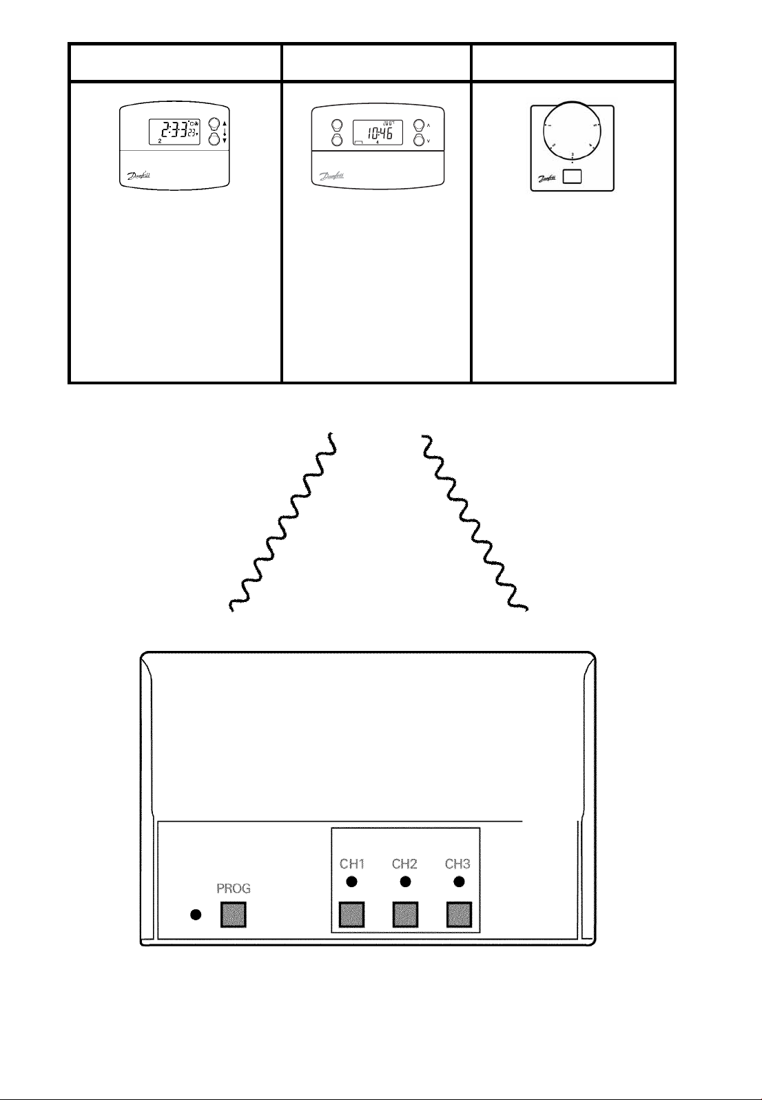
A B C
TP5000-RF TP7000-RF RET B-RF
TP5.2-RF TP75-RF CET B-RF
TP5E-RF WP75-RF
RT51-RF (LEARN
RT52-RF button under
RT1-RF setting dial)
RT2-RF
433.92 MHz
30m (max)
RX1 RX2 RX2C
RX3 RX3B RX3B-VF
3
Page 4

4
Page 5

(GB) Wiring Details / (F) Détails du câblage interne / (D) Elektrischer
Anschluss / (ES) Detalles de conexionado / (DK) Ledningsforbindelser / (NL)
Aansluitschema / (GR) ЛерфпмЭсейет ухсмЬфщузт / (PL) Szczegóły połączeń
/ (LT) Informacija apie laidus / (I) Dettagli collegamento
GB F D ES DK
Electronics Electronique Elektronik Electrónica Elektronik
COM COM Potentialfreie Kontakte Común Potentialefri kontakt
On Marche EIN On Tændt
Off Arrêt AUS Off Slukket
Zone Zone Zone Zona Zone
Boiler Chaudière Heizgerät Caldera Kedel
CH Chauffage Central Zentralheizung Calefacción central Centralvarme
HW Eau Chaude Heisswasser Agua caliente Varmt brugsvand
NL GR PL
Elektronica Ηλεκτρονικά
COM COM (Κοινό)
Aan ON
Uit OFF
Zone Ζώνη
Ketel Μπόιλερ
Centrale
verwarming
Warm tapwater Ζεστό νερό
Κεντρική
θέρμανση
RX1 & RX2
Układy elektroniczne
sterownika
Styk beznapięciowy
Styk: załącz
Styk: wyłącz
Strefa
Bojler
Centralne ogrzewanie
Gorąca woda
LT
Elektroninė sistema Elettronica
COM (įprasta) COM
On On
Off Off
Zona Zona
Boileris Caldaia
Centrinis šildymas Riscaldamento
Karštas vanduo
IT
centrale
Acqua calda
RX1 & 2 (3055 12/01)
COM
Note: For mains voltage applications link terminals L and 2.
5
Page 6

RX2C
RX2C (3082 04/02)
RX3
RX3 (3056 12/01)
6
Page 7

RX3B
Pump
Live
From
Boiler
RX3B (3057 12/01)
Boiler
Switched
Live
RX3B-VF
7
Page 8

NL - Technische gegevens
NEDERLANDS TECHNISCHE GEGEVENS
Radiografi sche ontvanger voor draadloze (klok)thermostaten.
Type thermostaat: zie bladzijde 3
Voedingsspanning 230Vac ± 15%, 50Hz
Constructienorm BS EN 60730-2-1, EN 300-220-1
Maximum omgevingstemperatuur 45°C
Relais contact RX1 - 1 x SPDT, type 1B
RX2 - 1 x SPDT, 1 x SPST, type 1B
RX3 - 1 x SPDT, 2 x SPST, type 1B
Maximum contactbelasting 264Vac, 3 (1) A (Totale stroom)
Dichtheid IP40
Straling Graad 2
Maximum ontvangstbereik 30 meter
Bedrijfsfrequentie 433,92 MHz
Software-klassifi catie Klasse A
Nominale piekspanning 2,5kV
Kogeltest 75°C
NL - Technische gegevens
18
Page 9

NL - Inbedrijfstelling
Volg onderstaande stappen om de thermostaat bij de ontvanger
aan te melden. Raadpleeg bladzijde 3 voor het thermostaattype.
Stap 1. Type A Druk 3 seconden gelijktijdig op de toetsen en +
Type B Druk 3 seconden op de LEARN toets
Type C Verwijder de instelknop en druk 3 seconden op
de LEARN toets (bevindt zich onder de instelknop)
De knop pas terugzetten nadat het aanmeldproces is voltooid
N.B.: De thermostaat zendt nu gedurende 5 minuten een
aanmeldsignaal uit.
Stap 2. Druk binnen 5 minuten na Stap1 gedurende 3 seconden
gelijktijdig op PROG en CH1 van de RX ontvanger. De
groene LED naast PROG licht kort op. De thermostaat is
nu gereed voor gebruik.
Stap 3. Druk op de knop ▲ of ▼ van de thermostaat om de
temperatuur te verhogen of te verlagen om te control
eren of de thermostaat op de juiste wijze schakelt.
RX-2C, RX-3B-VF, RX-3:
Druk eerst op een willekeurige toets van de zojuist
aangemelde thermostaat om het testsignaal te beëin
digen. Herhaal vervolgens voor de overige thermostaten
Stap 1, 2 en 3, nu echter met de knoppen CH2 resp.
CH3 van de RX ontvanger.
Uitsluitend tijdens
aanmelden
gebruiken
CH1 CH2 CH3
PROG
LED, licht rood op
wanneer een kanaal
is ingeschakeld
NL - Inbedrijfstelling
LED, licht kort groen
op ter indicatie van een
correct aangemelde
thermostaat
Kanaal toetsen, eventueel te gebruiken om een
kanaal handmatig in te schakelen wanneer de
verbinding met de thermostaat is verbroken.
De ontvanger schakelt terug naar automatisch
wanneer de verbinding weer tot stand is gekomen.
19
Page 10

www.danfoss.com/BusinessAreas/Heating
Part No 30622 Issue 02 05/05
 Loading...