

Page 1
Data sheet Lockshield valve type RLV
with facility for connection to drain tap
Application
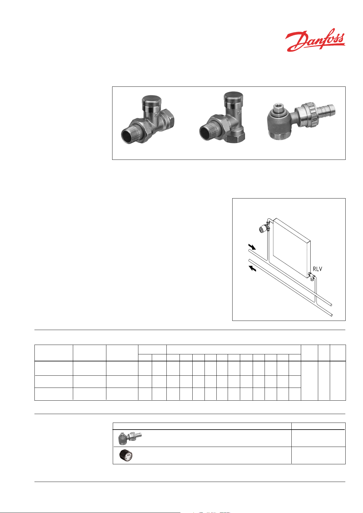
RLV Straight RLV Angle Drain tap
By means of a lockshield valve, type RLV,
every radiator can be shut off individually to
allow trouble-free maintenance or repair without affecting other radiators in the system.
In order to avoid deposition and corrosion the
composition of the hot water must be in accordance with the VDI 2035 guideline (Verein
Deutscher Ingenieure).
The lockshield valve, type RLV, is available in
an angle version as well as a straight version.
Finish: plain brass or nickel plated.
System
The RLV lockshield valves can be preset to
limit the max. water flow within the following
setting area:
RLV 10: k
RLV 15: kv = 2.5 m3/h
RLV 20: k
= 1.8 m3/h
v
= 3.0 m3/h
v
Factory setting is fully open valve. Dimensions
correspond to DIN 3842-1.
Accessories for RLV:
- a drain tap for draining or filling the water in
the raditator,
- a brass handwheel: a tool which is used
when radiators with RLV lockshield valves
are removed.
Ordering and data
Type
DN 10 angle 003L0141 003L0131 3/8 3/8 0.15 0.35 0.45 0.6 0.9 1.2 1.5 1.6 1.7 1.8 1.8
DN 10 straight 003L0142 003L0132
DN 15 angle 003L0143 003L0133 1/2 1/2 0.2 0.4 0.5 0.65 1.0 1.3 1.7 1.9 2.1 2.3 2.5 10 16 120
DN 15 straight 003L0144 003L0134
DN 20 angle 003L0145 003L0135 3/4 3/4 0.2 0.4 0.6 0.8 1.3 1.8 2.2 2.4 2.6 2.8 3.0
DN 20 straight 003L0146 003L0136
1)
RLV can be connected to PEX, Alupex, steel or copper tubings by Danfoss compression fittings.
Code no.
nickel plated
Code no.
plain brass
Connections
ISO 7-1
Syst. Rad. 0.25 0.5 0.75 1 1.5 2 2.5 3 3.5 4 kvs
Flow limitation: kv-values (m3/h) for no. of turns
Max.
working
press.
Test
press.
Max.
water
temp.
Accessories
CD-ST VDQBH202 © Danfoss 09/2004 1
Product Code no.
Drain tap with 3/4“ hose nozzle
Brass handwheel:
Replaces the thermostat temporarily when the radiator is drained
003L0152
013G3300
Page 2
Data sheet Lockshield valve type RLV
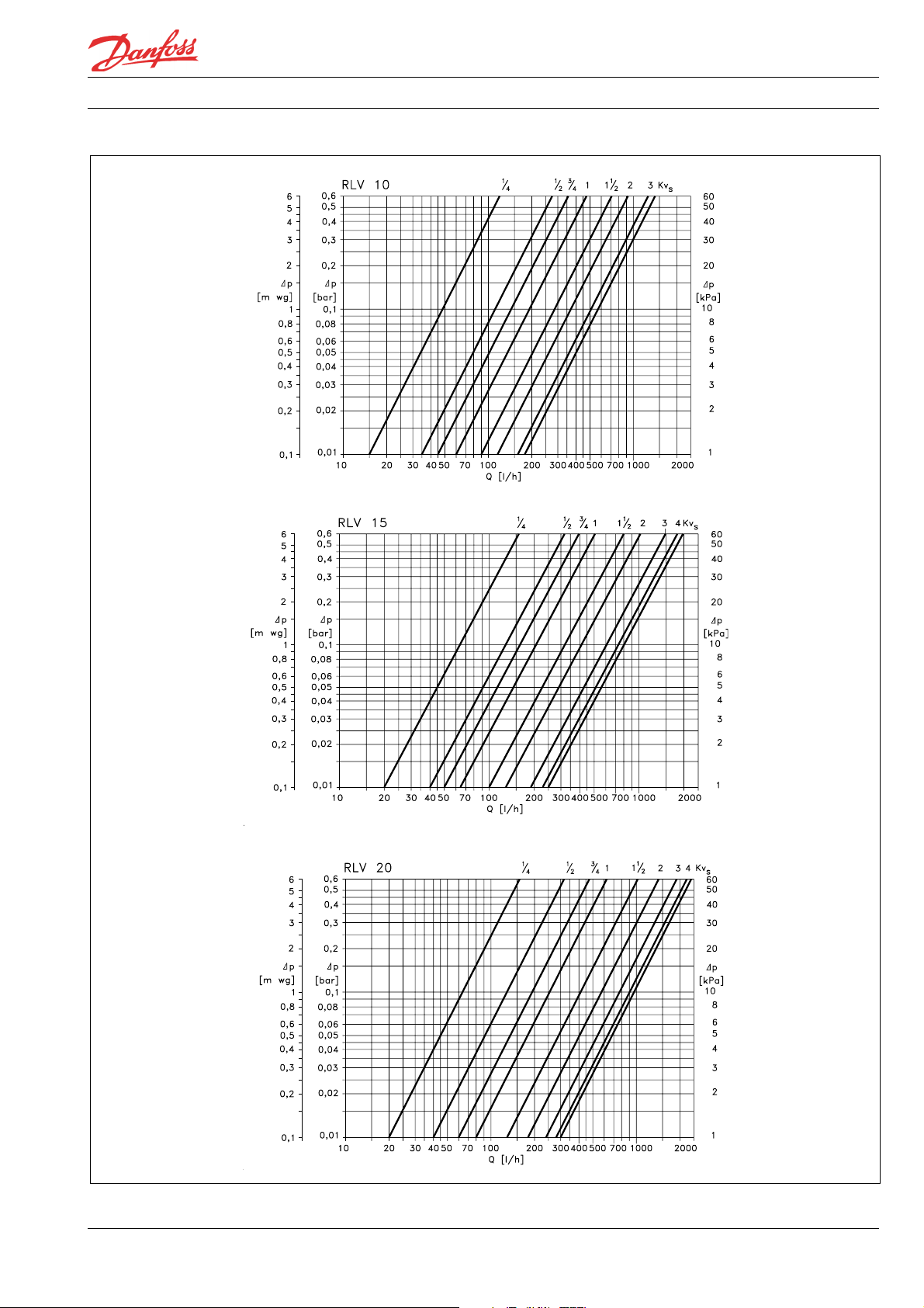
Setting and regulation Setting of max. water flow:
- Close the valve by means of a 6 mm Allen
key.
- Regulate the water flow by opening the
valve. The capacity diagrammes on the
opposite page show the water flow at ¼ - 4
turns and for fully open valve (k
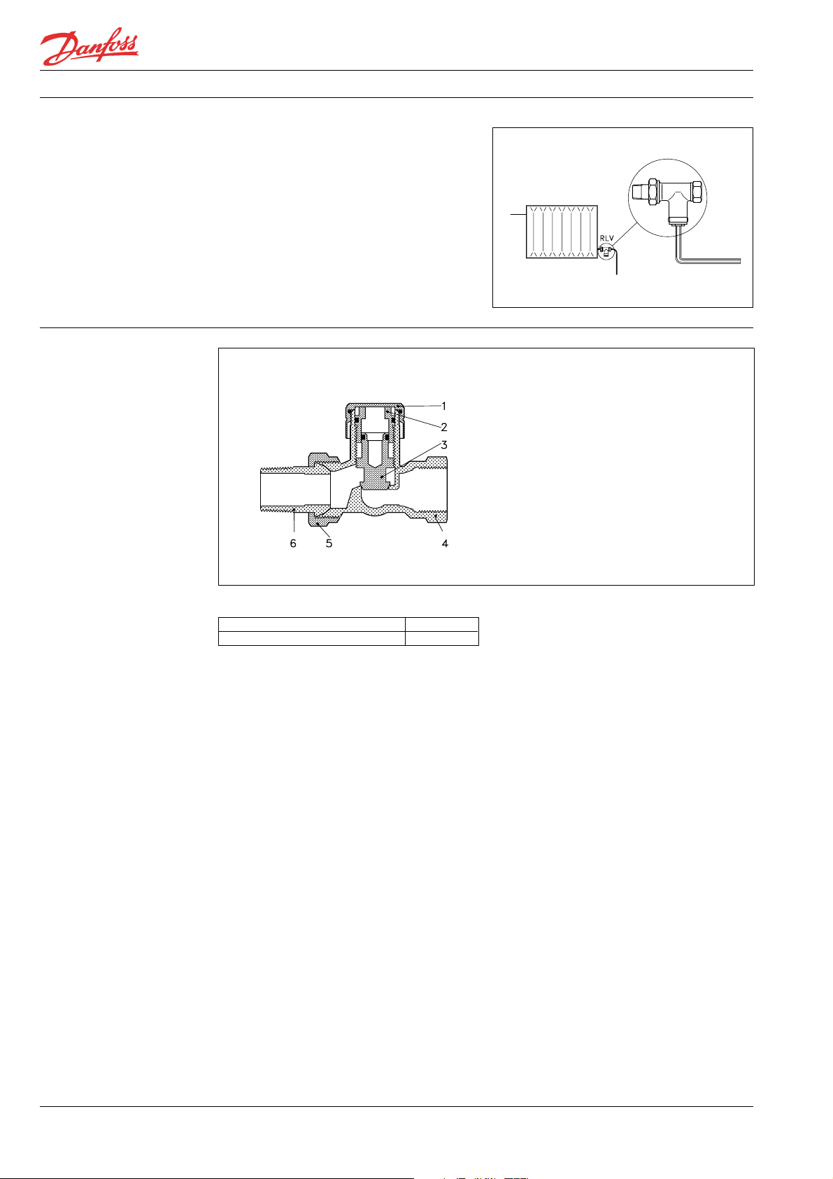
Construction
).
vs
1. Cover
2. Guide sleeve
3. Shut-off cone
4. Valve body
5. Union nut
6. Nipple
Material in contact with water
Valve body and other metal parts Ms 58
O-ring EPDM
2 VDQBH202 © Danfoss 09/2004
CD-ST
Page 3
Data sheet Lockshield valve type RLV
Capacity
CD-ST VDQBH202 © Danfoss 09/2004 3
Page 4
Data sheet Lockshield valve type RLV
Mounting
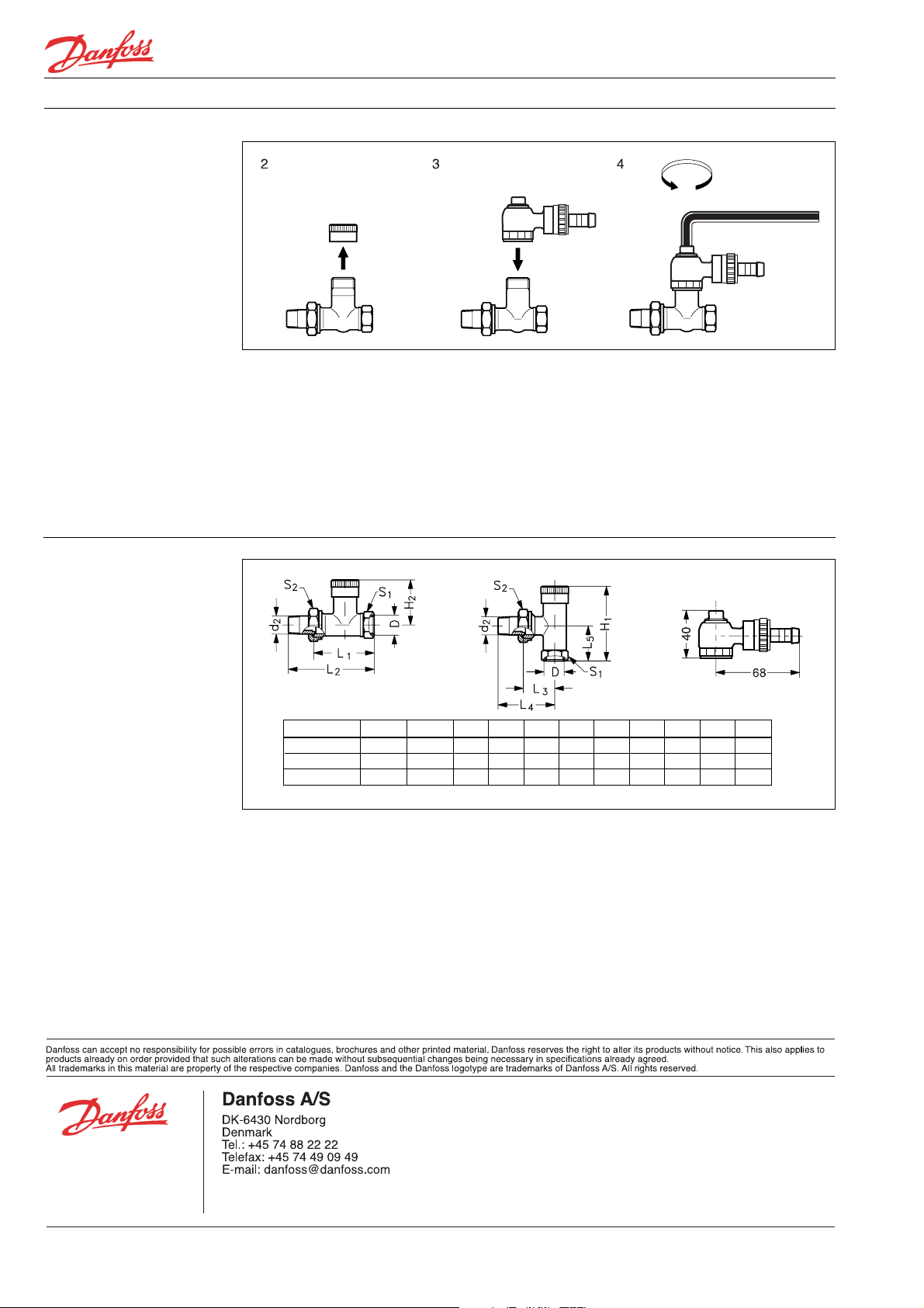
Dimensions
RLV
RLV is intended for mounting on the outlet
of the radiator. To enable subsequent
draining of the radiator water, the lockshield
valve should be mounted with its cover
towards the front.
Drain tap
For mounting and operation of the drain tap,
the following procedure is recommended:
Type D d
RLV 10 Rp3/8 R 3/8 57 40 51 75 27 51 23 22 27
RLV 15 R
RLV 20 R
1/2 R 1/2 63 41 53 80 30 57 27 27 30
p
3/4 R 3/4 63 40 61 92 34 65 30 32 37
p
H1H2L1L2L3L4L5S1S
2
1. Shut off the radiator inlet valve. As a
safety precaution the thermostatic
operator should be replaced by a Danfoss
manual shut off handle, code no.
013G3300.
2. Remove the cover and shut off the valve.
3. Mount the drain tap and align the drain
branch, which can revolve in any direction.
4. Open valve for draining by means of a 6
mm Allen key.
2
4 VDQBH202 © Danfoss 09/2004
CD-ST
 Loading...