

Page 1
RET B + RF
Electronic dial setting thermostat with LCD display
User & Installation Instructions
®
Certification Mark
Page 2

GB
F
D
ES
DK
NL
G
Installation Instructions 3-9
User Instructions 10-14
Instructions d’installation 15-20
Instructions d’utilisateur 21-23
Installationsanweisungen 24-29
Inbetriebnahme-Instruktion 30-32
Instrucciones de instalación 33-38
Instrucciones del usuario 39-41
Instruktions vejledning 42-47
Brugervejleding 48-50
Installatie handleiding 51-56
Instructiesevoor Gebruik 57-59
ПдзгЯет егкбфЬуфбузт 60-65
ПдзгЯет чсЮузт 66-68
2
Instrukcja instalacji 69-74
P
Instrukcja Użytkownika 75-77
Montavimo instrukcijos 78-83
LT
Informacija Vartotojui 84-86
Istruzioni per l’uso 87-92
I
Istruzioni per l’utente 93-95
Page 3

Installation Instructions
GB
Features
RET B (RF) / RET B-LS (RF) / RET B-NSB
(RF)
Contact rating 10 - 230 Vac, 3 (1) (excl. North America)
Contact rating
10 - 24 Vac, 50/60Hz, 3(1)A
(N.America)
Temperature Accuracy ±1°C
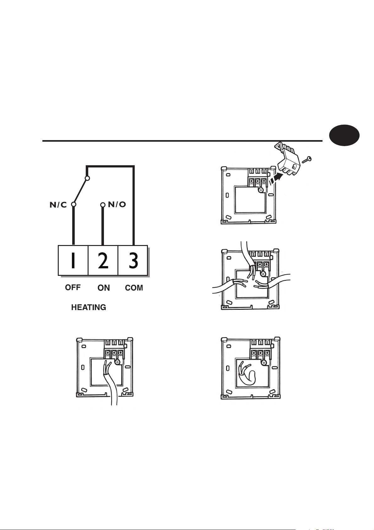
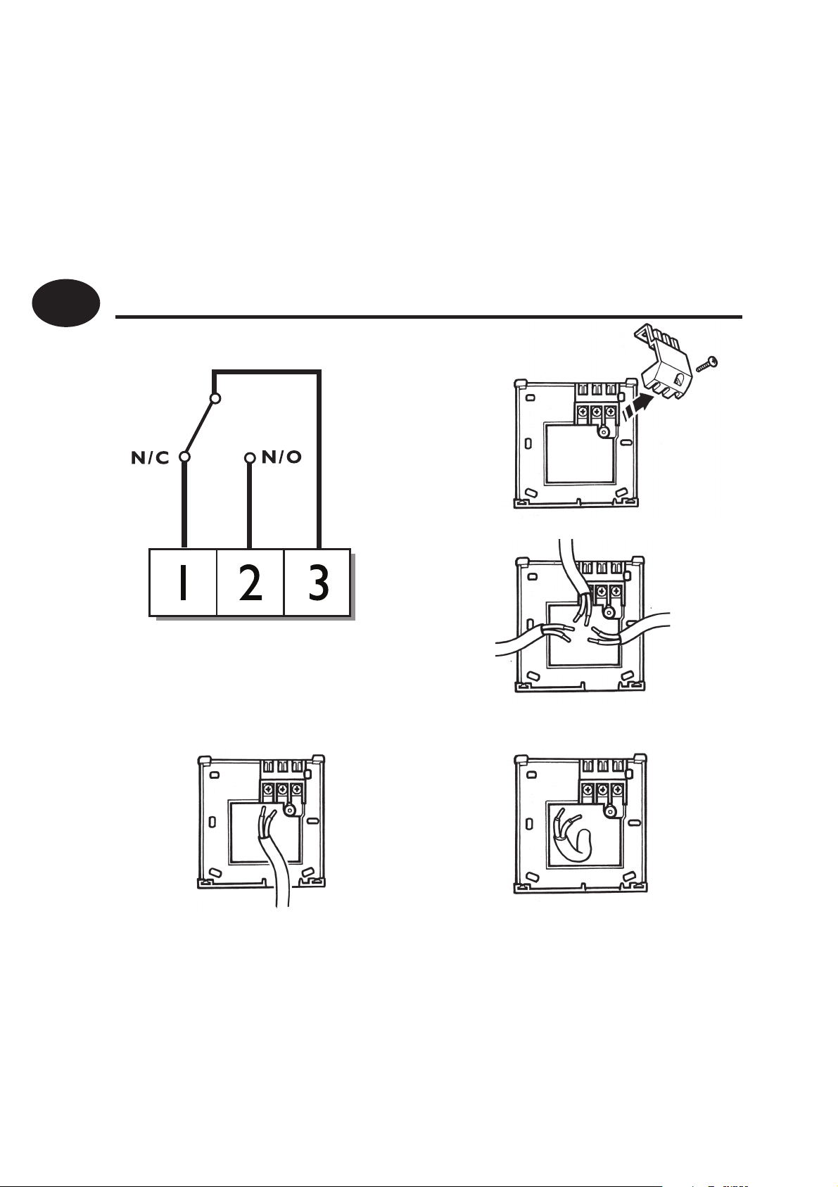
Contact Type SPDT Type 1B
Transmitter frequency 433.92 MHz (RF models)
Transmitter range 30m max (RF models)
Power Supply 2 x AA/MN1500 alkaline batteries
Control Pollution
Degree 2
Situation
Rated Impulse Voltage 2.5 kV
Designed to meet BS EN 60730-2-9 (EN 300220 for RF)
Installation Instructions
Ball Pressure Test 75°C
Temperature Range 5-30°C
Dimensions (mm) 85 wide x 86 high x 42 deep
Important note RF products: Ensure that there are no large metal objects, such as boiler
cases or other large appliances, in line of sight between the transmitter and receiver as
these will prevent communication between thermostat and receiver.
3
Page 4

GB
Installation Instructions
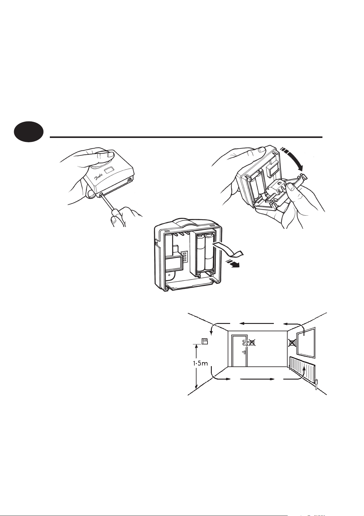
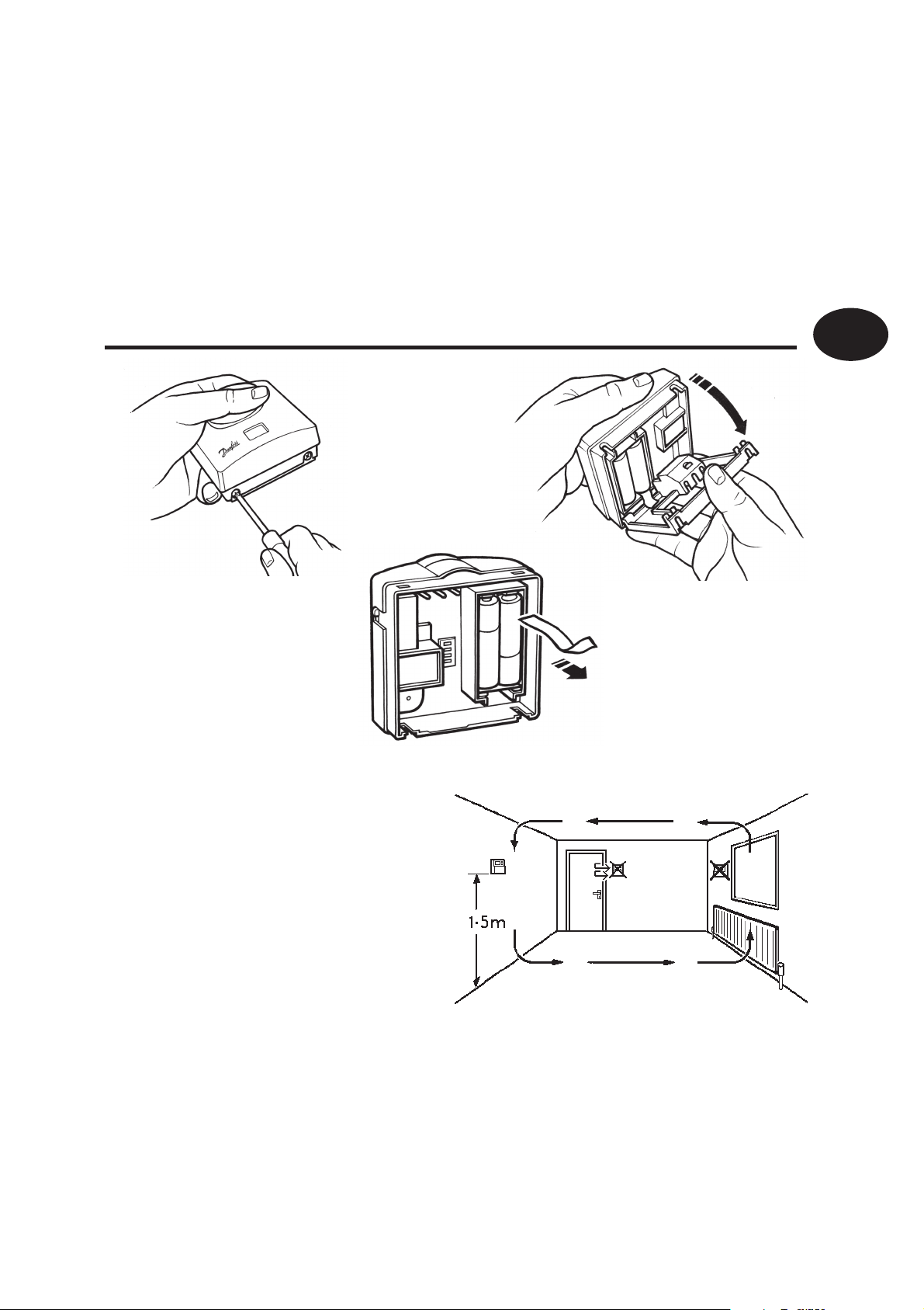
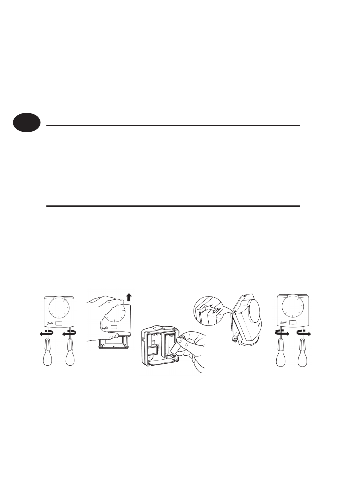
Mounting
4
Fix at a height of 1.5m
approx from the oor,
away from draughts or
heat sources such as
radiators, open res or
direct sunlight.
Page 5
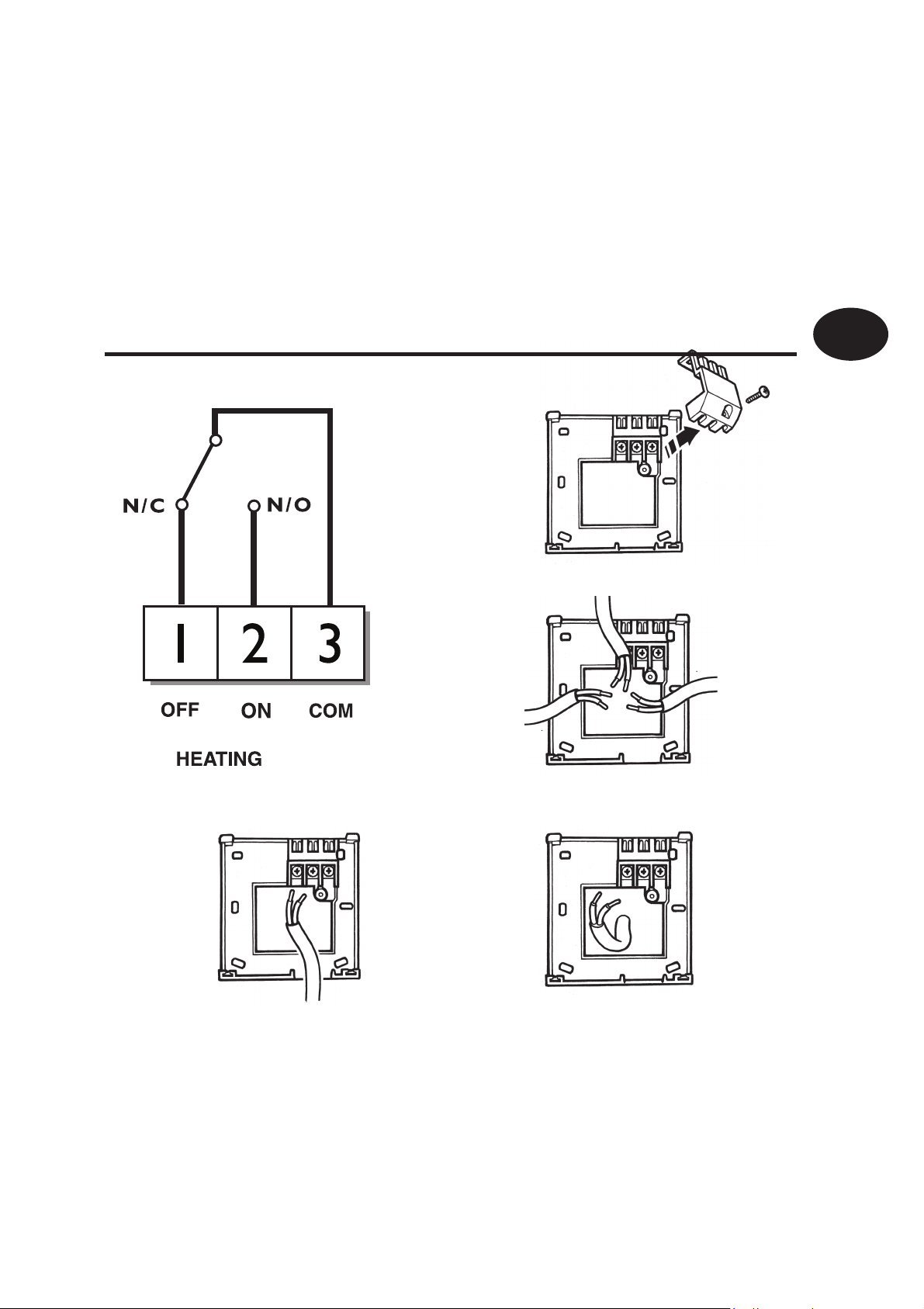
Wiring (not RF models)
RET-B (3050 12/01)
GB
Installation Instructions
5
Page 6
GB
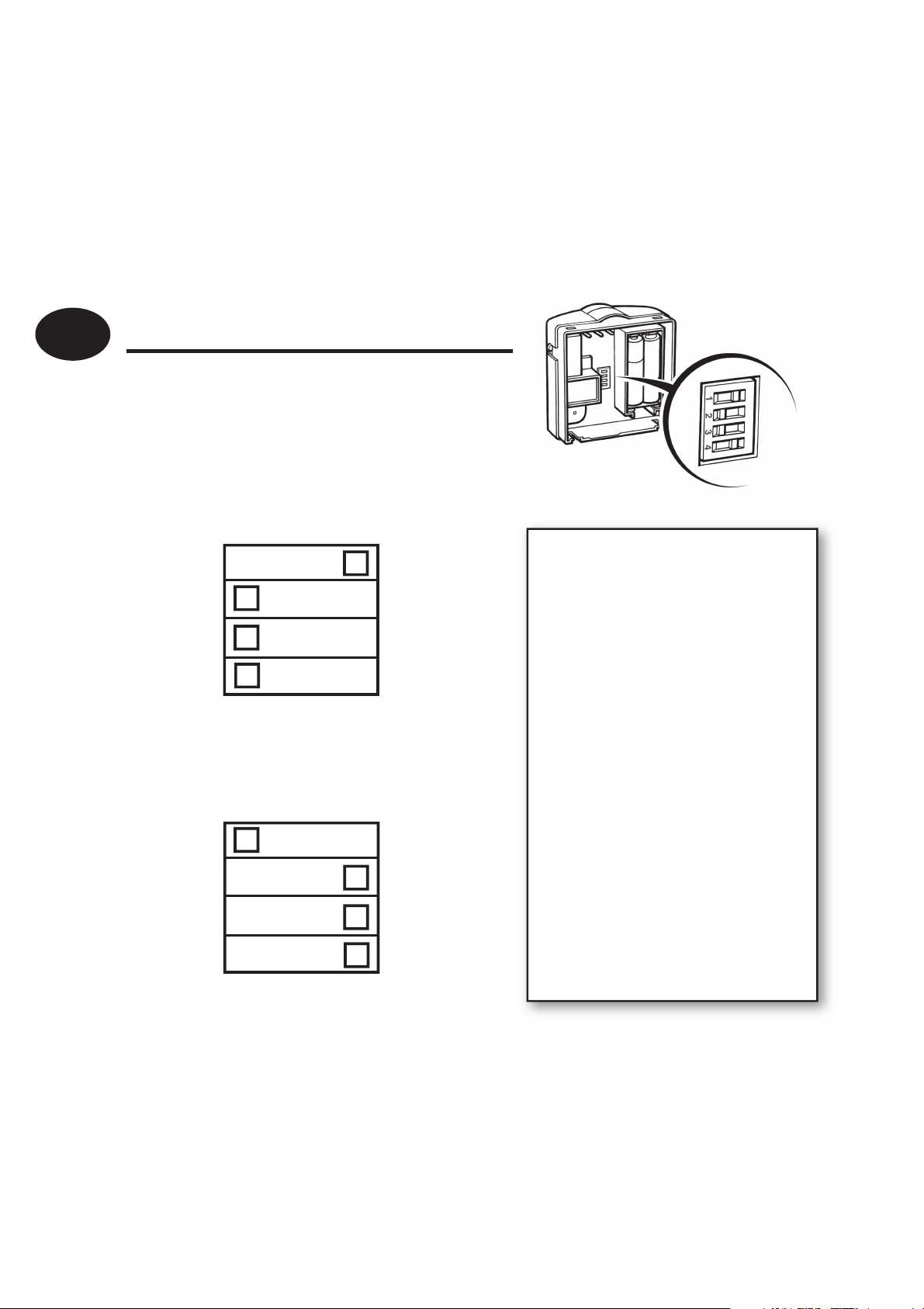
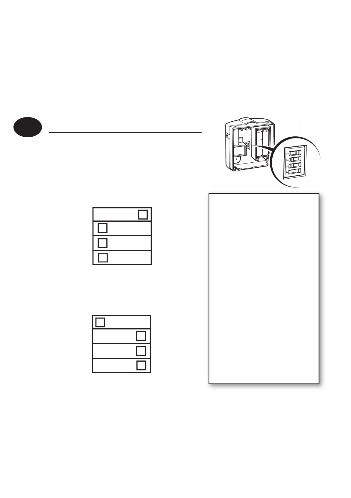
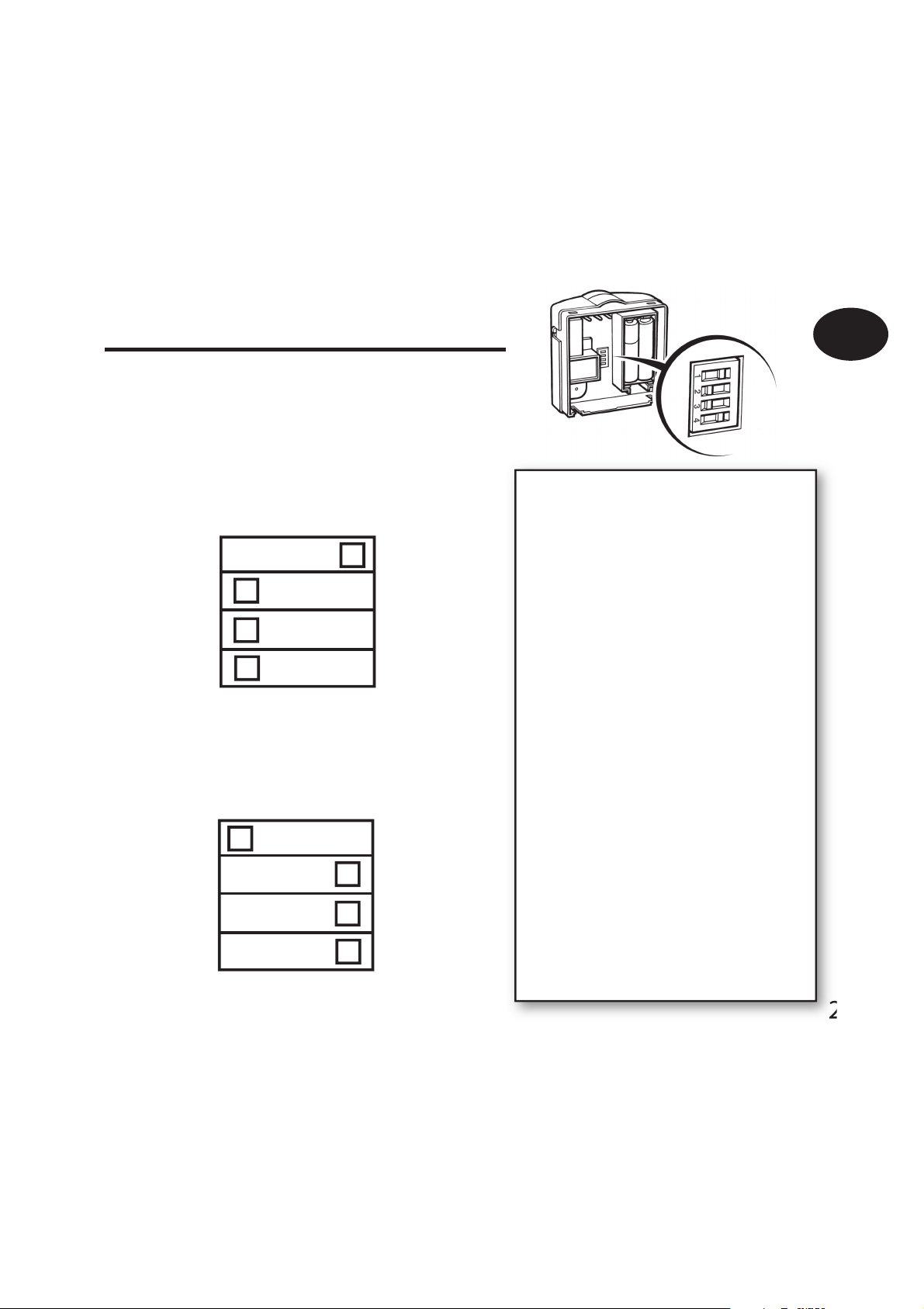
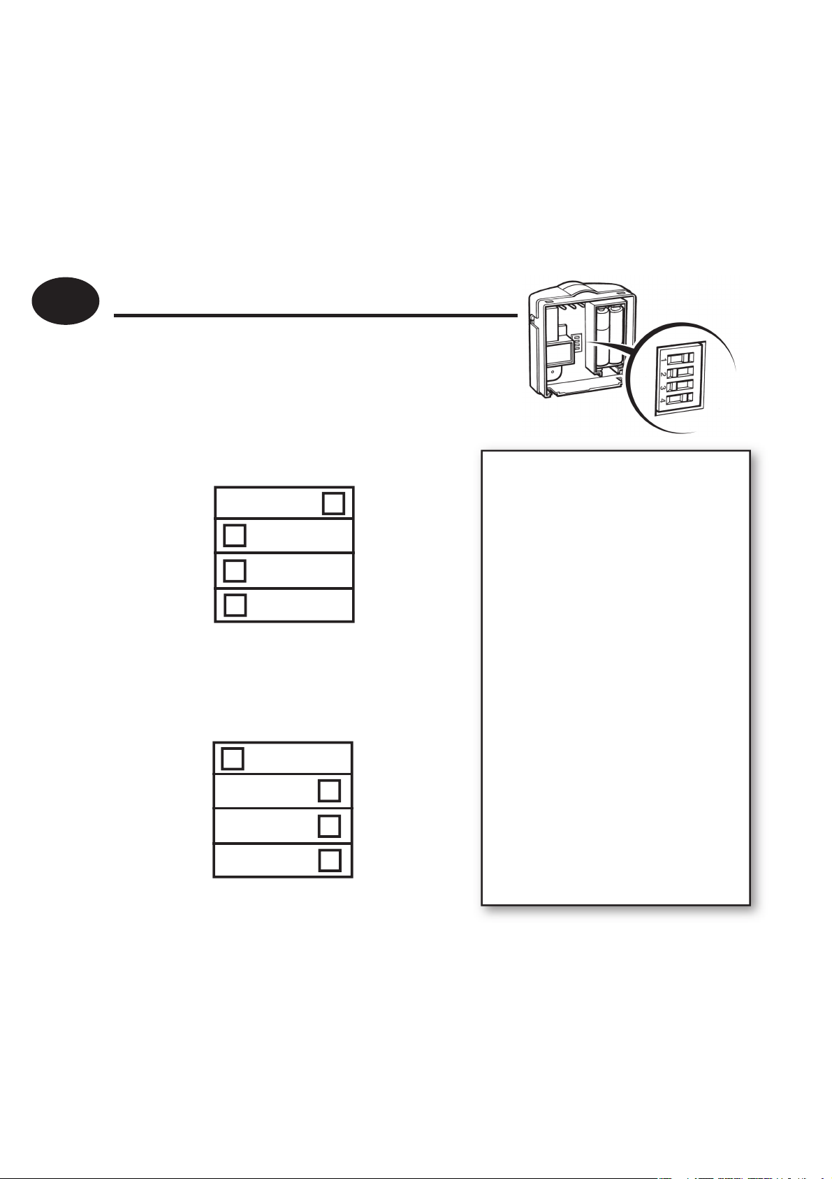
DIL switch settings
Slide the DIL switches to the settings
required (see below)
Heating selection
COOL
ON/OFF
6 CYCLES
°F
Installation Instructions
Cooling selection
COOL
NO DELAY
4 MIN DELAY
°F
HEAT
CHRONO
3 CYCLES
°C
HEAT
COMPRESSOR
DELAY
2 MIN DELAY
°C
ON/OFF - boiler switches ON
when below set temperature
and OFF when above
CHRONO feature which res the boiler
at regular intervals to maintain
a set temperature, achieving a
constant ambient environment
for the user.
use 6 Cycles for radiator
systems
use 3 Cycles for
under oor heating
energy saving
6
Page 7

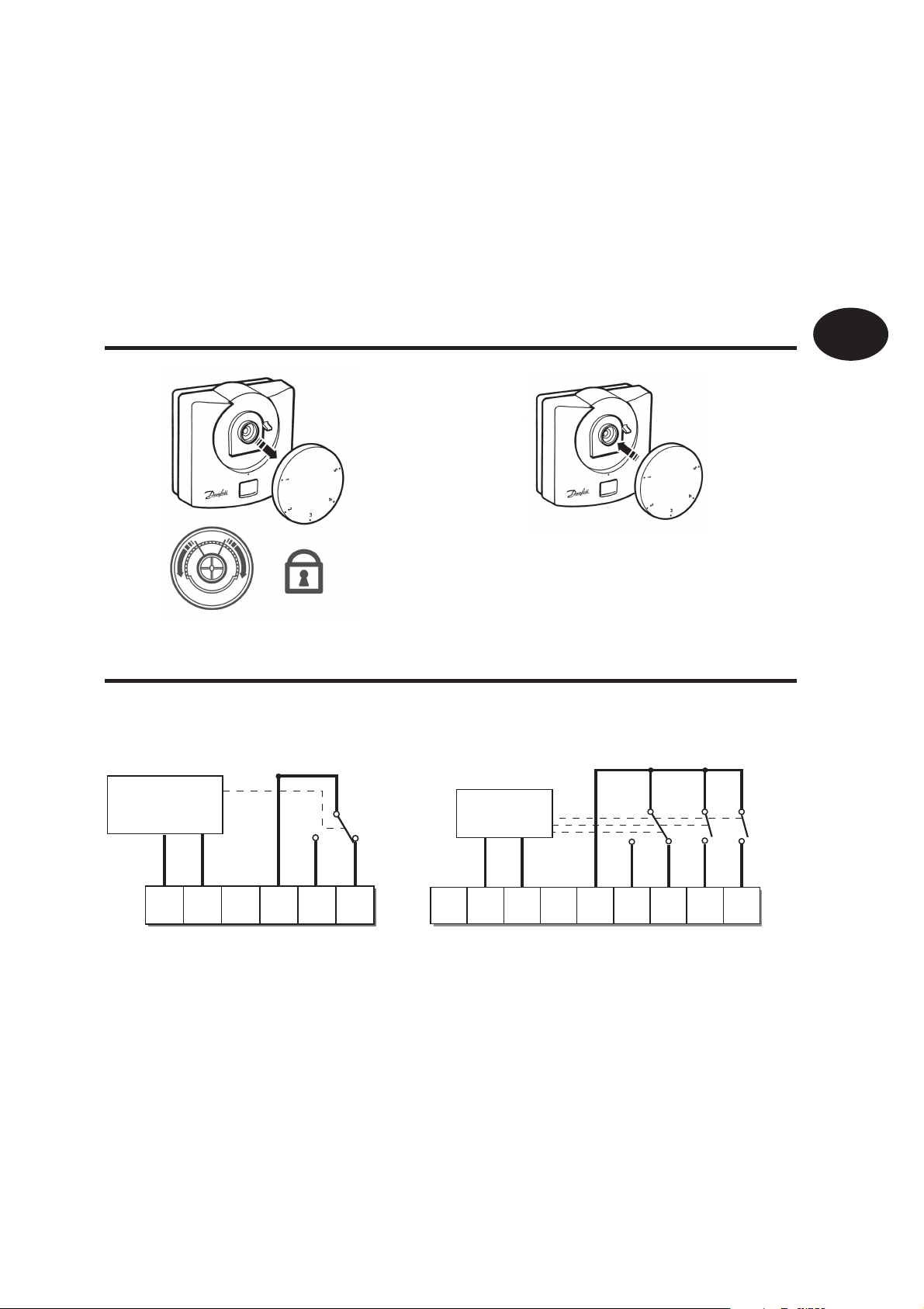
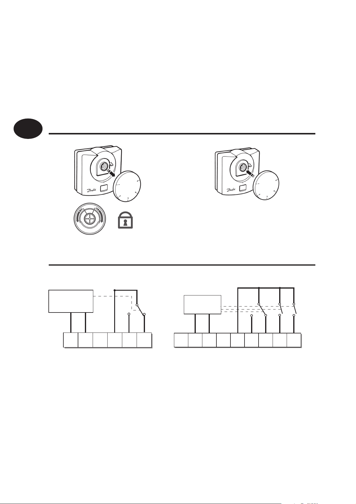
Locking & Limiting
Receiver Wiring (RF only)
RX1 RX2 and RX3
GB
Installation Instructions
ELECTRONICS
N
L
12
COM
3
ZONE
1 ON
4
ZONE
1 OFF
ELECTRONICS
A
B
N
C1
L
345
2
COM
ZONE
1 ON
ZONE
1 OFF
ZONE
2 ON
6
ZONE
3 ON
Note: 1) For mains voltage operated systems, link terminal 2 to mains live supply
2) Power supply to unit must not be switched by timeswitch
TERMINAL 6
RX3 ONLY
7
Page 8
GB
Installation Instructions
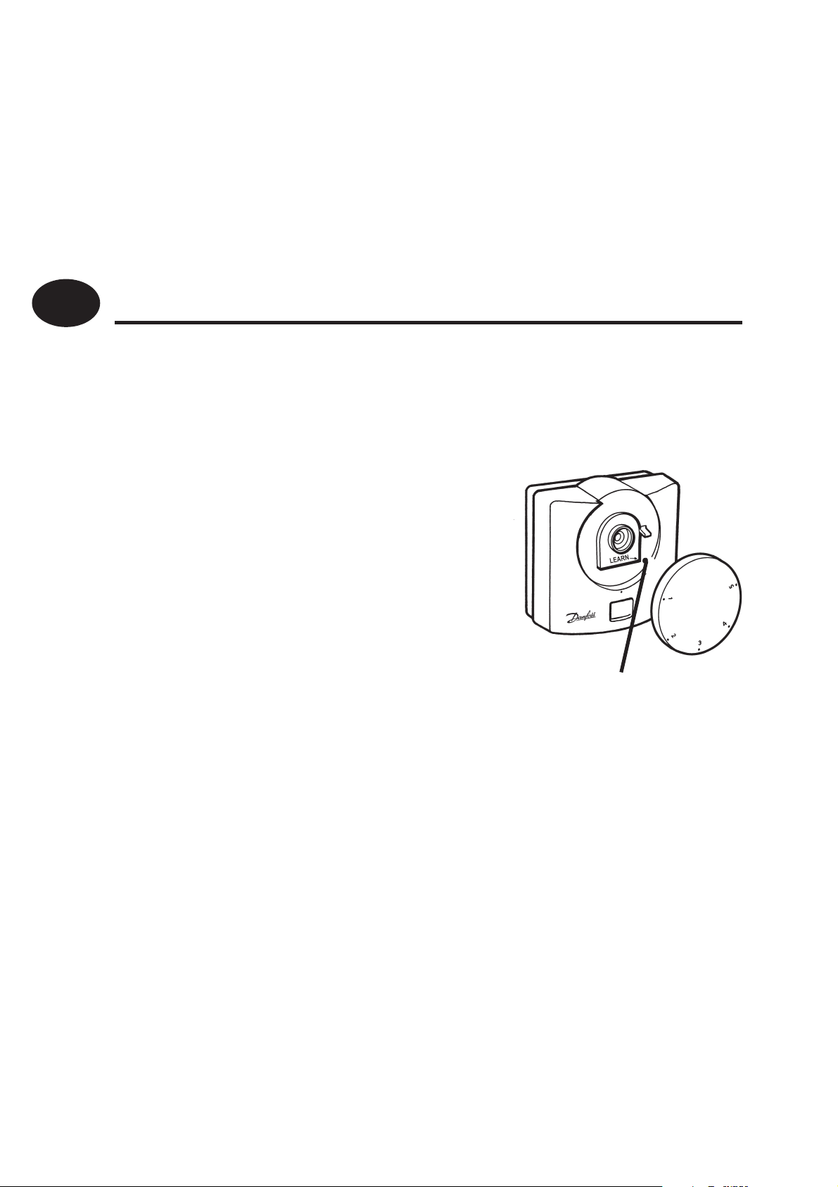
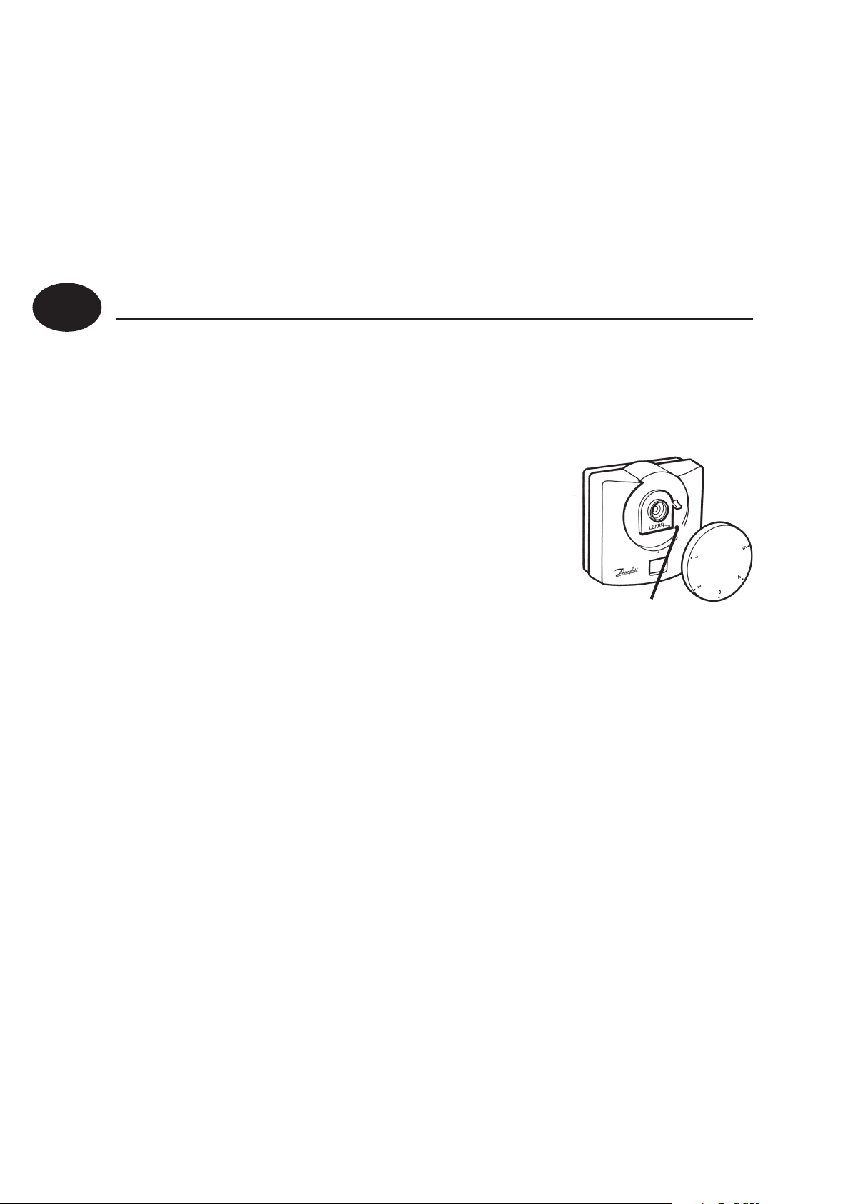
Commissioning (RF only)
If the thermostat and the receiver have been supplied
together in a combined pack, the units have been paired in
the factory and no commissioning is required (RX1 only).
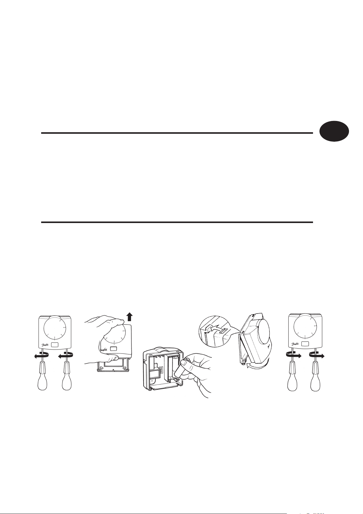
Step 1 RET B-RF
Position the setting dial to number
1. Remove dial, press & hold LEARN
button for 3 seconds (located under
setting dial).
Do not replace the setting dial yet
LEARN
8
NOTE: Thermostat now transmits
signal continuously for 5 mins.
Step 2 RX1
Press and hold buttons PROG and CH1 until green light
ashes.
Page 9

Step 3 RX2/RX3
For RX2 or RX3 repeat steps 1 and 2 for each thermostat and
channel, leaving at least 5 mins between the commissioning
of each thermostat.
Step 4 RET B-RF
To replace the thermostat setting dial, position the dial to
number 1.
GB
Installation Instructions
9
Page 10

GB
User Instructions
What is a room thermostat?
... an explanation for householders. A room thermostat simply
switches the heating system on and o as necessary. It works by
sensing the air temperature, switching on the heating when the air
temperature falls below the thermostat setting, and switching it o
once this set temperature has been reached.
10
Turning a room thermostat to a higher setting will not make the
room heat up any faster. How quickly the room heats up depends
on the design of the heating system, for example, the size of boiler
and radiators.
Neither does the setting a ect how quickly the room cools down.
Turning a room thermostat to a lower setting will result in the room
being controlled at a lower temperature, and saves energy.
Page 11

The heating system will not work if a timeswitch or programmer has
switched it o .
The way to set and use your room thermostat is to nd the lowest
temperature setting that you are comfortable with, and then leave
it alone to do its job. The best way to do this is to set the room
thermostat to a low temperature – say 18°C – and then turn it up by
one degree each day until you are comfortable with the temperature.
You won’t have to adjust the thermostat further. Any adjustment
above this setting will waste energy and cost you more money.
If your heating system is a boiler with radiators, there will usually
GB
be only one room thermostat to control the whole house. But you
can have di erent temperatures in individual rooms by installing
thermostatic radiator valves (TRVs) on individual radiators. If
you don’t have TRVs, you should choose a temperature that is
reasonable for the whole house. If you do have TRVs, you can
choose a slightly higher setting to make sure that even the coldest
room is comfortable, then prevent any overheating in other rooms
by adjusting the TRVs.
Room thermostats need a free ow of air to sense the temperature,
so they must not be covered by curtains or blocked by furniture.
Nearby electric res, televisions, wall or table lamps may prevent the
thermostat from working properly.
User Instructions
11
Page 12

GB
User Instructions
User Instructions
Display
The LCD displays actual room temperature until the setting dial
is moved.
Setting the temperature
Turn setting dial to required temperature. The selected
temperature will ash in the LCD to signify it is showing set
temperature.
After a short period the display stops ashing and shows actual
room temperature.
12
Thermostat status (heat mode only)
A ame symbol will be lit whenever the thermostat is calling
for heat.
Page 13
Thermostat status (cool mode only)
A snow ake symbol will be lit whenever the thermostat is
calling for cooling. If this is seen to ash, the thermostat output
is delayed for a short period to prevent compressor damage.
Low battery indication
A battery symbol will ash in the display when batteries require
GB
replacement. Batteries should be replaced within 15 days, after
which the thermostat will turn o the load it is controlling.
When this happens “Of” will be displayed.
IMPORTANT: alkaline batteries must be used.
User Instructions
13
Page 14
GB
User Instructions
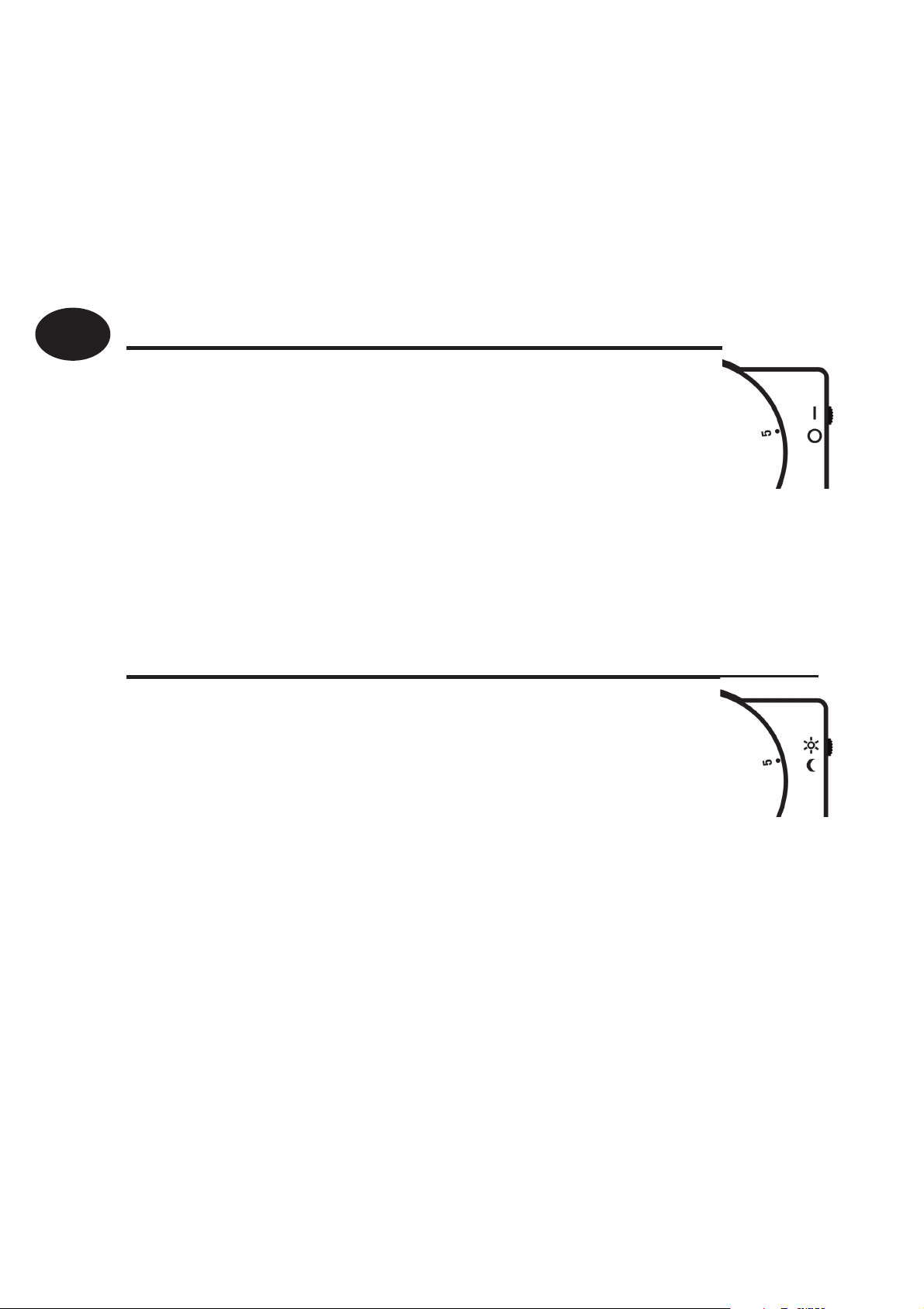
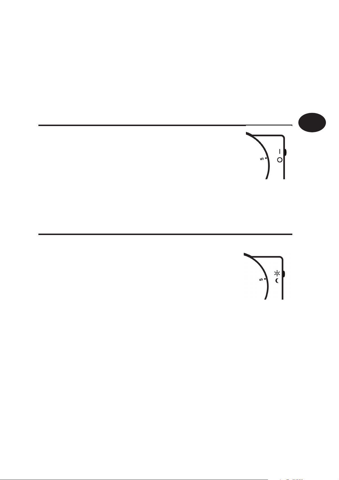
RET B-LS model only
This model is tted with an Auto/O switch.
When the switch is set in “I” position the thermostat
controls at the temperature set by the setting dial.
When set to “O” the thermostat output is turned o and
“Of” is displayed.
RET B-NSB model only
This model is tted with a Day/Night switch.
When the switch is set to the “Sun Symbol”, the thermostat
14
controls at the temperature set by the setting dial.
When set to the “Moon symbol”, the thermostat controls
at 4°C below the temperature set by the setting dial.
NOTE: if used to control cooling, thermostat controls 4°C higher, with
switch in MOON position.
Page 15

Instructions d’installation
RET B (RF), RET B-LS (RF)
Caractéristiques
& RET B-NSB (RF)
Caractéristique de contact 10 - 230 Vca, 3 (1) A
Précision de la température ±1°C
Type de contact SPDT Type 1B (inverseur)
Fréquence de fonctionnement 433.92 MHz (RF)
Portée émetteur 30m max (RF)
Alimentation 2 piles alcalines x AA / MN1500
Niveau de recyclage Degré 2
Tension de choc nominale 2.5 kV
F
Normes de fabrication BS EN 60730-2-9
Essai à la bille 75°C
Plage de témperatures 5-30°C
Dimensions (mm) 85 larg x 86 haut x 42 épaiss
Remarque importante pour version sans l (RF):Veiller à ce qu’aucun gros objet métallique (caisson de chaudière ou autres gros appareils domestiques) ne fasse obstacle aux
communications entre le thermostat et le récepteur.
Instructions d’installation
15
Page 16
F
Instructions d’installation
Montage
Fixez l’appareil à une
16
hauteur d’environ 1,5
m du sol, à l’écart des
courants d’air ou des
sources de chaleur telles
que radiateurs, ammes
nues ou lumière directe du
soleil.
Page 17
Câblage (versions câblées seulement)
F
Instructions d’installation
17
Page 18
F
Réglages d’installateur
Faites glisser les microcontacts dans
les positions requises (voir ci-dessous).
Chau age
ON/OFF
6 CYCLES
Instructions d’installation
Froid
COOL
NO DELAY
4 MIN DELAY
COOL
°F
°F
HEAT
CHRONO
3 CYCLES
°C
HEAT
COMPRESSOR
DELAY
2 MIN DELAY
°C
ON/OFF (Marche/Arrêt) – la
chaudière se met en marche
lorsque la température est
inférieure à la température
dé nie et s’arrête lorsque la
température est supérieure.
Chrono-proportionnel
fonction d’économie
d’énergie qui déclenche
la chaudière à intervalles
réguliers pour maintenir une
température dé nie, o rant
un environnement ambiant
constant à l’utilisateur.
Utilisez 6 cycles pour les
systèmes de radiateur.
Utilisez 3 cycles pour le
18
chau age sous plancher.
Page 19
Verrouillage & Limitation
Câblage du Récepteur RX (modèles RF uniquement)
RX1 RX2 & RX3
F
Instructions d’installation
ELECTRONICS
N
L
12
COM
3
ZONE
1 ON
4
ZONE
1 OFF
ELECTRONICS
A
B
N
C1
L
345
2
COM
ZONE
1 ON
ZONE
1 OFF
ZONE
2 ON
6
ZONE
3 ON
NB. Pour les systèmes alimentés sur secteur, reliez la borne 2 à la phase du secteur.
TERMINAL 6
RX3 ONLY
19
Page 20
F
Instructions
Si le thermostat émetteur et le récepteur ont été fournis
ensemble dans un kit, ces deux éléments peuvent
communiquer directement sans manipulation particulière
(Modèles RX1 uniquement).
Etape 1 RET B-RF - Régler la molette
(modèles RF uniquement)
Instructions d’installation
20
sur position 1.
pendant 3 secondes (situé sous le cadran
de réglage). Ne pas replacer le cadran de
réglage pour l’instant.
Remarque : Le thermostat transmet
maintenant en continu pendant 5 minutes.
Etape 2 RX1 - Appuyez sur les touches PROG et CH1 en les
maintenant enfoncées pendant 3 secondes jusqu’à ce que le
voyant vert clignote une fois.
Etape 3 RX2/RX3 - Pour RX2 ou RX3, répétez les points 1 et 2
pour chaque thermostat et canal, en laissant au moins 5 min entre
la mise en service de chaque thermostat.
Etape 4 RET B-RF -
Pressez la touche LEARN
LEARN
Replacer la molette en l’ayant réglée sur 1.
Page 21

Instructions d’utilisateur
Ecran
L’écran digital a che la température ambiante, tant que le
bouton de réglage n’est pas actionné.
Régler la température
Tournez le cadran de réglage jusqu’à la température désirée.
La température désirée clignote alors sur l’écran digital, a n de
montrer la température e ectivement réglée.
F
Après une courte période, l’a chage ne clignote plus et montre
la température ambiante mesurée.
Mode du thermostat (thermostat en demande de chau e)
Le symbole « amme » apparaît quand le thermostat est en
demande de chau e.
Instructions d’utilisateur
21
Page 22
F
Mode du thermostat (thermostat en demande de froid)
Le symbole « ocon de neige » apparaît quand le thermostat
est en demande de froid. Si l’écran clignote, la sortie du
thermostat est temporisée pendant un court instant pour
éviter d’endommager le compresseur.
Indication de changement de piles
Le symbole « pile » apparaît quand il est nécessaire de changer
les piles. Elles doivent être remplacées dans les quinze jours.
Passé ce délai, le thermostat est inopérant et « Of » apparaît sur
l’écran. Pour le changement des piles.
IMPORTANT – toujours utiliser des piles alcalines.
Instructions d’utilisateur
22
Page 23
Modèle RET B-LS seulement
Ce modèle est conçu avec un mode Arrêt/Auto.
Quand le sélecteur est sur « I », le thermostat
régule à la température a chée à l’écran.
Quand le sélecteur est sur « O », le thermostat
est inopérant et « Of » s’a che à l’écran.
Modèle RET B-NSB seulement
Ce modèle est conçu avec un mode Jour/Nuit.
Quand le sélecteur est sur le symbole « soleil »,
le thermostat régule à la température a chée
à l’écran.
F
Instructions d’utilisateur
Quand le sélecteur est sur le symbole « lune »,
le thermostat régule à une température
inférieure de 4 degrés à la température
sélectionnée à l’écran.
REMARQUE – si utilisée pour commander le refroidissement, la
commande du thermostat ajoute 4°C lorsque le commutateur est
sur la position LUNE.
23
Page 24

D
Installationsanweisungen
Funktionsbeschreibung
Schaltleistung 10 - 230 Vac, 3 (1)
Temperaturgenauigkeit ±1°C
Schaltertyp Umschaltkontakt / potentialfrei / SPDT
Reichweite des Senders 433.92 MHz (RF models)
Transmitter range Max. 30m (RF)
Stromversorgung 2 x AA/MN1500 Alkaline-Batterien
Emissionswerte Grad 2
Nennspannungsimpuls 2.5 kV
Bauweise BS EN 60730-2-9 (EN 300220 for RF)
Installationsanweisungen
Verformbarkeit unter Druck 75°C
Temperaturbereich 5-30°C
Abmessungen (B x H x T) 85 x 86 x 42 mm
RET B (RF) / RET B-LS (RF)
& RET B-NSB (RF)
24
Wichtiger Hinweis RF: Achten Sie darauf, dass sich zwischen Thermostat und Empfänger
keine größeren Metallobjekte wie Boilergehäuse oder andere große Geräte be nden, da
ansonsten die Kommunikation zwischen dem Thermostaten und dem Empfänger gestört
werden kann.
Page 25
Befestigung
In einer Höhe von 1,5 m über
D
Installationsanweisungen
dem Boden, frei von Luftzug
oder Wärmequellen, wie
z. B. Heizkörpern, o enen
Feuerstellen oder direktem
Sonnenlicht, befestigen.
25
Page 26
D
Verkabelung (nur bei Kabelversion)
AUS EIN COM
Installationsanweisungen
26
HEIZUNG
Page 27
Einstellungen
Schieben Sie die DIL-Schalter auf die
gewünschten Einstellungen (siehe
unten)
Heizen
D
EIN/AUS - Heizgerät schaltet
EIN, wenn die tatsächliche
COOL
ON/OFF
6 CYCLES
°F
Kühlen
COOL
NO DELAY
4 MIN DELAY
°F
HEAT
CHRONO
3 CYCLES
°C
HEAT
COMPRESSOR
DELAY
2 MIN DELAY
°C
Temperatur unter der
eingestellten Temperatur liegt
und AUS, wenn oberhalb.
Zeitproportional (Chrono)
– Energiesparfunktion,
bei der das Heizgerät in
regelmäßigen Intervallen
anspricht, um eine
eingestellte Temperatur zu
halten und eine konstante
Umgebungstemperatur für
den Benutzer zu erreichen.
Verwenden Sie für
•
Heizkörpersysteme 6 Zyklen.
•
Verwenden Sie für
Fußbodenheizungen 3
Zyklen.
Installationsanweisungen
27
Page 28
D
Sperren und Begrenzen
Verdrahtung der Empfangseinheit RX (nur RF-Modelle)
RX1 RX2 & RX3
Installationsanweisungen
ELEKTRONIK
N
Hinweis: Bei Systemen, die per Netzspannung betrieben werden, Anschlussklemme
(2) an stromführende Leitung (L) anschließen (brücken).
28
L
12
COM
3
ZONE
1 EIN
4
ZONE
1 AUS
A
ELEKTRONIK
C1
B
L
N
345
2
COM
ZONE
1 EIN
ZONE
1 AUS
ZONE
2 EIN
KLEMME 6
NUR BEI RX3
6
ZONE
3 EIN
Page 29

Inbetriebnahme-Instruktion
Wurde das Thermostat zusammen mit dem Receiver in einem
kombinierten Paket geliefert, ist dieses eine Einheit und die
Einstellung/Programmierung erfolgte bereits im Werk (nur
RX1-Modelle).
Befolgen Sie zur Frequenzabgleichung des RX-Empfängers auf das
Thermostatsignal die unten aufgeführten Schritte 1 bis 4.
1. RET B-RF
Die Einstellscheibe auf Position 1 drehen
D
und abnehmen.
angebrachten Knopf LEARN für 5 Sekunden
gedrückt halten.
Die Einstellscheibe bitte noch nicht
einsetzen.
Anmerkung: Thermostat sendet nun 5 Minuten lang ein Signal.
2. RX1 - Knöpfe PROG und CH1 für 5 Sekunden gedrückt halten.
3. RX2/RX3 - Wiederholen Sie für RX2 oder RX3 die Schritte 1 und 2
für jedes Thermostat und jeden Kanal, wobei Sie ein Intervall von
mindestens 5 Minuten zwischen der Inbetriebnahme der jeweiligen Thermostate belassen müssen.
4. RET B-RF -
Die Einstellscheibe bei Position 1 wieder auf den
Den unter der Einstellscheib
LEARN
Thermostaten setzen.
Installationsanweisungen
29
Page 30

D
Benutzeranweisungen
Anzeige
Das LCD zeigt die aktuelle Raumtemperatur an, bis die
Einstellscheibe bewegt wird.
Einstellen der Temperatur
Durch Drehen der Einstellscheibe wird die gewählte Temperatur
auf dem blinkenden LCD angezeigt.
Benutzeranweisungen
Nach kurzer Zeit wird das Blinken eingestellt und die tatsächliche
30
Raumtemperatur angezeigt.
Thermostat-Status: (Thermostat im Heizmodus)
Das Symbol einer Flamme wird immer angezeigt, wenn der
Thermostat im Heizmodus ist.
Page 31

Thermostat-Status: (Thermostat im Kühlmodus)
Das Symbol einer Schnee ocke wird immer angezeigt,
wenn der Thermostat im Kühlmodus ist. Bei Blinken wird
der Thermostatausgang für kurze Zeit verzögert, um
Kompressorschaden zu vermeiden.
Batteriewarnanzeige
Bei notwendigem Batteriewechsel wird im Display ein
Batteriesymbol angezeigt. Batterien müssen innerhalb von 15
Tagen erneuert werden. Nach diesem Zeitraum schaltet sich
der Thermostat und dessen Regellast ab. ‚O ‘ wird im Display
D
angezeigt.
WICHTIG – es müssen immer Alkalibatterien Typ AA LR6
verwendet werden.
Benutzeranweisungen
31
Page 32

Nur RET B-LS-Modell
D
Dieses Modell ist mit einem Aus/Auto-Schalter
ausgestattet. Bei Schalterstellung auf “I” regelt der
Thermostat eine auf der Einstellscheibe eingestellte
Temperatur.
Bei Schalterstellung auf “O” wird die Thermostatleistung
abgeschaltet und “O ” wird im Display angezeigt.
Nur RET B-NSB-Modell
Dieses Modell ist mit einem Tag/Nacht-Schalter
ausgestattet. Bei Schalterstellung auf dem
Benutzeranweisungen
Sonnensymbol regelt der Thermostat eine auf der
32
Einstellscheibe eingestellte Temperatur.
Bei Schalterstellung auf dem Mondsymbol regelt
der Thermostat eine Temperatur, die 4°C unter der auf der
Einstellscheibe eingestellten Temperatur liegt.
HINWEIS – bei Verwendung des Thermostats zur Kühlung regelt dieses
bei Einstellung auf MOND um 4°C höher.
Page 33

Instrucciones de instalación
RET B(RF)/RET B-LS(RF)/
Características
RET B-NSB(RF)
Carga de contactos 10 - 230 V.c.a, 3 (1) A
Precisión de temperatura ±1°C
Contacto SPDT tipo 1B
Frecuencia de funcionamiento 433.92 MHz (RF)
ES
Campo de acción del
30m max (RF)
transmisor
Alimentación 2 pilas alcalinas 1,5 V.
Control antipolución Grado 2
Rango impulsos de tensión 2.5 kV
Normativa BS EN 60730-2-9
Test prueba de bola 75°C
Gama de temperaturas 5-30°C
Dimensiones (mm) Ancho 85 X Alto 86 X Profundo 42
Nota importante RF: Asegurar que la línea de visión entre el transmisor y el termostato
no haya quedado obstaculizada por objetos grandes metálicos tales como calderas u otros
aparatos grandes ya que estos impedirían la comunicación entre el termostato y el receptor.
Instrucciones de instalación
33
Page 34

ES
Montaje
Montarlo a una altura de
Instrucciones de instalación
aproximadamente 1,5 m desde
el suelo, lejos de corrientes
de aire o de fuentes de calor
tales como radiadores, fuegos
descubiertos o rayos solares
34
directos.
Page 35

Cableado - solo versiones de conexion permanente
CALEFACCION
ES
Instrucciones de instalación
35
Page 36

ES
Ajustes del instalador
Mover los conmutadores DIL hasta las
posiciones de ajuste requeridas (ver
abajo)
Calefacción
COOL
ON/OFF
6 CYCLES
°F
Refrigeración
Instrucciones de instalación
COOL
NO DELAY
4 MIN DELAY
°F
HEAT
CHRONO
3 CYCLES
°C
HEAT
COMPRESSOR
DELAY
2 MIN DELAY
°C
ON/OFF : la caldera cambia a ON
cuando está a una temperatura
inferior a la establecida y a OFF
cuando está a una temperatura
superior.
Crono-proporcional :
con guración de ahorro de
energía en la cual la caldera se
enciende a intervalos periódicos
para mantener una temperatura
establecida, obteniéndose
una temperatura ambiente
constante para el usuario
Utilizar 6 ciclos para los
sistemas de radiadores
Utilizar 3 ciclos para la
calefacción por Suelo Radiante
36
Page 37

Bloquear y Limitar
Cableado del Receptor RX (solo para modelos RF)
RX1 RX2 & RX3
ES
ELECTRONICS
N
L
12
COM
3
ZONE
1 ON
4
ZONE
1 OFF
ELECTRONICS
A
B
N
C1
L
345
2
COM
ZONE
1 ON
ZONE
1 OFF
ZONE
2 ON
TERMINAL 6
RX3 ONLY
6
ZONE
3 ON
N.B. Para sistemas que funcionen con la tensión de la red unir el terminal 2
con la alimentación de la red .
Instrucciones de instalación
37
Page 38

ES
Instrucciones de puesta en marcha
Si el termoestato y el receptor se han suministrado
juntos en un paquete combinado, las unidades han sido
emparejadas en la fábrica y no será necesaria ninguna
operación (solo modelos RX1).
Paso 1 RET B-RF - Ajustar la posición del
dial a 1. retirar el dial y pulsar y mantener
pulsados LEARN durante 3 segundos
(situado debajo del disco de jación).
No vuelva a colocar el disco de jación
todavía.
Nota: el termostato transmite ahora de
forma continua durante 5 minutos.
Paso 2 RX1 - Oprimir los botones PROG y CH1 y mantenerlos
Instrucciones de instalación
oprimidodurante 3 segundos hasta que la luz verde dé un
destello.
Paso 3 RX2/RX3 - Para RX2 o RX3 repetir los pasos 1 y 2 para
cada termostato y canal, dejando pasar al menos 5 minutos
entre la puesta en servicio de cada termostato.
Paso 4 RET B-RF - Colocar el dial de ajuste en la posición 1.
38
LEARN
Page 39

Instrucciones del usuario
Pantalla
El display muestra la temperatura ambiente actual hasta que
se mueva el dial.
Ajuste de la temperatura
Girar el dial de ajuste hasta la temperatura requerida. Las
temperaturas se visualizan en el display parpadeando.
Una vez jada la temperatura y después de un corto periodo de
tiempo el display deja de parpadear y muestra la temperatura
ambiente actual.
ES
Instrucciones del usuario
Estado del termostato: ( termostato en modo calefacción)
El símbolo de la llama aparecerá en el display cuando el
termostato demande calefacción.
39
Page 40

Estado del termostato:
ES
( termostato en modo refrigeración)
El símbolo de la nieve aparecerá en el display cuando el termostato
demande refrigeración. Si ésta se ve destelleando, la salida del
termostato se demora durante un corto período de tiempo para
evitar que el compresor sufra daños.
Indicación de batería baja
El símbolo de la batería lucirá en el display cuando las pilas
requieran ser reemplazadas. Las pilas deberían cambiarse en
un plazo de 15 días, en otro caso el termostato se desconectará
y aparecerá en el display “Of”. Para el cambio de pilas.
IMPORTANTE – usar pilas alcalinas
Instrucciones del usuario
40
Page 41

Solo modelo RET B-LS
Este modelo incluye un interruptor O /Auto.
Situando el interruptor en la posición “I” el termostato
controlará la temperatura seleccionada en el dial.
En la posición “O” el termostato se desconectará y
aparece “Of” en el display.
Solo modelo RET B-NSB
Este modelo incluye un interruptor “Dia/Noche.
ES
Situando el interruptor en la posición del símbolo
del sol el termostato controlará la temperatura
seleccionada en el dial.
En la posición del símbolo de la luna, el termostato controla a una
temperatura 4ºC por debajo de la seleccionada en el dial.
NOTA – si se utiliza para controlar la refrigeración, el termostato controla
4ºC más con el conmutador en el modo MOON.
Instrucciones del usuario
41
Page 42

DK
Instruktions vejledning
Tekniske data RET B (RF)/RET B-LS (RF)/RET B-NSB (RF)
Kontaktbelastning 10 - 230 Vac, 3 (1) A
Temperaturnøjagtighed ±1°C
Kontakt type SPDT Type 1B
Sendefrekvens 433.92 MHz (RF)
Rækkevidde 30m max (RF)
Forsyning 2 x AA/MN1500 alkaline batterier
Omgivelser Grad 2
Nominel Impuls Spænding 2.5 kV
Instruktions vejledning
Opfylder BS EN 60730-2-9 (EN 300220 : RF)
42
Kugle tryk test 75°C
Temperaturområde 5-30°C
Dimensioner (mm) 85 (h) x 86 (b) x 42 (d)
Vigtig note ved RF produkter: Vær opmærksom på at større metal genstande, som kedler
eller andre store elektriske maskiner, placeret mellem sender og modtager kan formindske
modtage og sende forholdene og evt. forhindre kommunikationen mellen termostat og
modtager.
Page 43

Montering
DK
Instruktions vejledning
Monter den i en højde på
ca. 1,5 m fra gulvet væk fra
lufttræks- eller varmekilder
såsom radiatorer, åben ild
eller direkte sollys.
43
Page 44

DK
Ledningsføring (ledningstrukne versioner)
Instruktions vejledning
44
Page 45

Montørindstillinger
Indstil vippeafbryderne som ønsket
(se nedenfor)
DK
Opvarmning
COOL
ON/OFF
6 CYCLES
°F
Køling
COOL
NO DELAY
4 MIN DELAY
°F
HEAT
CHRONO
3 CYCLES
°C
HEAT
COMPRESSOR
DELAY
2 MIN DELAY
°C
1) ON/OFF - kedlen er ON,
når temperaturen er under
den indstillede temperatur,
og OFF, når temperaturen
er over den indstillede
temperatur
2) Tidsmæssig
proportionalitet
- energibesparelsesfunktion,
som opvarmer kedlen med
jævne mellemrum for at
bevare den indstillede
temperatur, hvorved
brugeren opnår en konstant
omgivende temperatur.
Brug seks kredsløb til
•
radiatorsystemer
Instruktions vejledning
Brug tre kredsløb til gulvvarme
•
45
Page 46

DK
Låsning og begrænsning
Ledningsføring (ledningstrukne versioner)
RX1 RX2 & RX3
Instruktions vejledning
46
ELECTRONICS
L
N
12
COM
3
ZONE
1 ON
4
ZONE
1 OFF
ELECTRONICS
A
B
N
C1
L
345
2
COM
ZONE
1 ON
ZONE
1 OFF
ZONE
2 ON
TERMINAL 6
RX3 ONLY
6
ZONE
3 ON
PS. I relation til systemer, der modtager netspænding, skal klemme 2 tilkobles
forsyningsnettet.
Page 47

Aktiveringsinstruktioner (ledningstrukne versioner)
Hvis termostat og modtager er leveret i sampak, er enhederne indstillet fra fabrik, og trin 1-5 kan derfor springes over
(Kun RX1 modeller).
Trin 1 RET B-RF
DK
Indstil termostaten på 1.
på knappen LEARN Placeret under
indstillingsknappen.
Sæt ikke indstillingsknappen på endnu.
Noter: Termostaten transmiterer nu
kontinuerligt i 5 minutter.
Trin 2 RX1 - Tryk knapperne PROG og CH1 ind i 3 sek.
Trin 3 RX2/RX3 - For RX2 og RX3 skal trin 1 og 2 gentages for
hver termostat og kanal, således at der er fem minutter mellem
ibrugtagning af hver termostat.
Trin 4 RET B-RF - Ved påsætning af indstillingsknappen skal
denne positioneres udfor 1.
Tryk i 3 sekunder
LEARN
Instruktions vejledning
47
Page 48

DK
Brugervejleding
Display
Displayet viser den aktuelle rumtemperatur indtil der drejes på
håndtaget.
Indstilling af temperaturen
Brugervejleding
Drej uret til den ønskede temperatur. Den valgte temperatur
vises med blinkende tal i displayet.
Efter en kort tid skifter displayet til at vise den aktuelle
rumtemperatur. Dette ses ved at tal i displayet stopper med
48
at blinke.
Termostat indstilling - opvarmning
I displayet vises et ” amme”-symbol så længe der er behov for
yderligere opvarmning.
Page 49

Termostat indstilling – køling
I displayet vises et frost-symbol så længe der er behov for
yderligere køling. Hvis uret blinker, er termostatudbyttet
forsinket i en kort periode for at forhindre beskadigelse af
kompressoren.
Low battery indication
Et ”batteri”-symbol vil blinke i displayet når batterierne skal
udskiftes. Batterierne bør da udskiftes indfor 15 dage for at
undgå at termostatfunktionen forsvinder. Hvis dette skulle ske
vises ”Of” i displayet.
VIGTIGT: Batterier af typen alkaline skal benyttes
DK
Brugervejleding
49
Page 50

Type RET B-LS
DK
Denne type er udstyret med en ”auto/o ”omskifter. Med omskifteren i position ”I” regulere
termostaten automatisk i forhold til den valgte
temperatur indstilling.
Med omskifteren i position ”O” er termostat
funktionen udkoblet og symbolet ”Of” vises i displayet.
Brugervejleding
Type RET B-NSB
Denne type er udstyret med en ”dag/nat”omskifter. Med omskifteren udfor ”sol-symbolet”
regulere termostaten automatisk i forhold til den
50
valgte temperatur indstilling.
Med omskifteren udfor ”måne-symbolet” sænkes
den valgte temperatur indstilling med 4°C.
BEMÆRK: Hvis benyttet til styring af køling vil thermostaten med
kontakten i MÅNE positionen regulere temperaturen 4°C højere.
Page 51

Installatie handleiding
Omschrijving RET B (RF)/RET B-LS (RF)/RET B-NSB (RF)
Maximum contactbelasting 10 - 230 Vac, 3 (1) A
Nauwkeurigheid ±1°C
Relaiscontact SPDT Type 1B, potentiaalvrij
Bedrijfsfrequentie (RF) 433.92 MHz
Zendbereik (RF modellen) 30m max
Voeding 2 x AA/MN1500 Alkaline batterijen
Stralingsniveau Graad 2
NL
Nominale piekspanning 2,5 kV
Constructienorm BS EN 60730-2-9 (EN 300220 : RF)
Kogeldruktest 75°C
Temperatuurbereik 5-30°C
Afmetingen (bxhxd) 85 x 86 x 42 mm
Belangrijk voor RF modellen: Let er op dat zich geen grote metalen voorwerpen, zoals
ketels of andere grote apparaten, in de gezichtslijn tussen thermostaat en ontvanger
bevinden, aangezien hierdoor de communicatie tussen thermostaat en ontvanger wordt
verhinderd.
Installatie handleiding
51
Page 52

NL
Montage
Installatie handleiding
52
Bevestig op een hoogte van
ongeveer 1,5 m vanaf de
vloer, niet op de tocht en uit
de buurt van warmtebronnen
zoals radiatoren, open vuur
of direct zonlicht.
Page 53

Aansluitingen (niet bij RF modellen)
NL
Installatie handleiding
53
Page 54

NL
Instellingen
Schuif de DIL-schakelaars naar de
gewenste instellingen (zie hieronder)
Verwarmen
COOL
ON/OFF
6 CYCLES
°F
Installatie handleiding
Koelen
COOL
NO DELAY
4 MIN DELAY
°F
HEAT
CHRONO
3 CYCLES
°C
HEAT
COMPRESSOR
DELAY
2 MIN DELAY
°C
ON/OFF – ON/OFF - de ketel
schakelt AAN wanneer de
temperatuur daalt tot onder de
ingestelde waarde en UIT bij
hogere temperaturen
Chrono-Proportional
– energiebesparende functie
die de ketel met regelmatige
tussenpozen inschakelt om
een ingestelde temperatuur
in stand te houden,
waardoor een constante
omgevingstemperatuur wordt
bereikt voor de gebruiker.
Gebruik 6 cycli voor
radiatorsystemen
Gebruik 3 cycli voor
54
vloerverwarming
Page 55

Blokkeren & Begrenzen
Aansluiting van ontvanger
(alleen bij RF modellen)
NL
RX1 RX2 & RX3
ELECTRONICS
N
L
12
COM
3
ZONE
1 ON
4
ZONE
1 OFF
N.B. Bij netspanning gevoede systemen dient klem 2 te worden aangesloten op de fase
van de netvoeding.
ELECTRONICS
A
B
N
C1
L
345
2
COM
ZONE
1 ON
ZONE
1 OFF
ZONE
2 ON
TERMINAL 6
RX3 ONLY
6
ZONE
3 ON
Installatie handleiding
55
Page 56

NL
Inbedrijfstelling van RF modellen
Als de thermostaat en de ontvanger in een setverpakking zijn
geleverd is de aanmeldprocedure al in de fabriek uitgevoerd
(enkel model RX1).
Volg onderstaande stappen om de thermostaat bij de ontvanger
aan te melden.
Stap 1 Verwijder de instelknop en druk 3 seconden
op de LEARN toets (bevindt zich onder de
instelknop). De knop pas terugzetten nadat
het aanmeldproces is voltooid. N.B. De
thermostaat zendt nu gedurende 5 minuten
Installatie handleiding
een aanmeldsignaal uit.
Stap 2 RX1 - Druk binnen 5 minuten na
Stap1 gedurende 3 seconden gelijktijdig op PROG en CH1 van
de RX ontvanger.
Stap 3 RX2/RX3 - Herhaal de stappen 1 en 2 voor RX2 of RX3
voor elke thermostaat en elk kanaal, wacht minstens 5 min. tussen de
inbedrijfstelling van elke thermostaat.
Stap 4 RET B-RF -
56
op de thermostaat
Zet de instelknop op stand 1.
LEARN
Plaats de instelknop in stand 1 weer terug
Page 57

Instructies voor Gebruik
Display
De display toont de gemeten ruimtetemperatuur totdat de
instelknop wordt verdraaid.
Instelling van de temperatuur
Draai de instelknop naar de gewenste temperatuur. Op de
display verschijnt knipperend de ingestelde temperatuur.
Na korte tijd stopt de display met knipperen en wordt de
NL
gemeten ruimtetemperatuur getoond.
Status thermostaat (verwarming)
Als de thermostaat in de verwarmingsstand staat (zie
installatie-instructies) verschijnt er een vlamsymbool in de
display wanneer de thermostaat warmte vraagt.
Instructies voor Gebruik
57
Page 58

NL
Instructies voor Gebruik
Status thermostaat (koeling)
Als de thermostaat in de koelstand staat (zie installatie-instructies)
verschijnt er een ijskristal-symbool in de display wanneer de
thermostaat koeling vraagt. Wanneer u die ziet knipperen wordt
de thermostaatuitvoer gedurende korte tijd vertraagd om schade
aan de compressor te voorkomen.
Lege batterij indicatie
Als de batterijen vervangen moeten worden verschijnt er een
batterij-symbool in de display. Als het symbool in de display
verschijnt moeten de batterijen binnen 15 dagen vervangen
worden anders schakelt de thermostaat zichzelf uit. In de
display verschijnt dan “OF”.
58
BELANGRIJK – gebruik alkaline batterijen
Page 59

Alleen het RET B-LS model
Dit model is voorzien van een AUTO/OFF schakelaar.
Als de schakelaar op “I” (AUTO) gezet wordt, regelt
de thermostaat volgens de temperatuur die op de
draaiknop is ingesteld.
De thermostaat kan worden uitgezet door de schakelaar op “O” te
zetten. De thermostaat schakelt dan niet meer in en in het display
verschijnt “OF”.
Alleen het RET B-NSB model
Dit model is voorzien van een dag-/nachtschakelaar.
NL
Als de schakelaar op het zonnetje wordt gezet regelt
de thermostaat volgens de temperatuur die op de
knop is ingesteld.
Als de schakelaar op het maantje wordt gezet wordt een
nachtverlaging van 4 ºC aangehouden.
N.B. – bij gebruik voor het regelen van koeling, thermostaatregeling 4°
C hoger, met de schakelaar in de MAAN-stand.
Instructies voor Gebruik
59
Page 60

GR
ПдзгЯет егкбфЬуфбузт
ЧбсбкфзсйуфйкЬ
ПнпмбуфйкЮ фймЮ ербцЮт 10 - 230 V Å.Ñ., 3 (1) A
БксЯвейб иесмпксбуЯбт ±1°C
Фэрпт ербцЮт SPDT фэрпх 1B
Ухчньфзфб рпмрпэ 433,92 MHz (мпнфЭлб RF)
ЕмвЭлейб рпмрпэ 30m мег. (мпнфЭлб RF)
РбспчЮ сеэмбфпт 2 блкблйкЭт мрбфбсЯет AA/MN1500
КбфЬуфбуз Элегчпх сэрбнузт Вбимпэ 2
ПнпмбуфйкЮ фЬуз рблмпэ 2,5 kV
ПдзгЯет егкбфЬуфбузт
УчедйбумЭнпт уэмцщнб ме BS EN 60730-2-9 (EN 300220 ãéá RF)
ДпкймЮ рЯеузт уцбЯсбт 75°C
РесйпчЮ иесмпксбуйюн 5-30°C
RET B (RF)/RET B-LS (RF)/RET B-NSB (RF)
60
ДйбуфЬуейт (mm) 85 рлЬфпт x 86 эшпт x 42 вЬипт
УзмбнфйкЮ узмеЯщуз гйб рспъьнфб RF: ВевбйщиеЯфе ьфй ден хрЬсчпхн мегЬлб
мефбллйкЬ бнфйкеЯменб, ьрщт ресйвлЮмбфб мрьйлес Ю Ьллет мегЬлет ухукехЭт,
уфзн прфйкЮ ехиеЯб мефбоэ фпх рпмрпэ кбй фпх дЭкфз ерейдЮ иб емрпдЯжпхн фзн
ерйкпйнщнЯб мефбоэ иесмпуфЬфз кбй дЭкфз.
Page 61

ЕгкбфЬуфбуз
GR
ПдзгЯет егкбфЬуфбузт
Уфесеюуфе уе эшпт ресЯрпх
1,5 m брь фп дЬредп,
мбксйЬ брь сеэмбфб Ю
рзгЭт иесмьфзфбт ьрщт
уюмбфб кблпсйцЭс, гхмнЮ
цльгб Ю Ьмеуз злйбкЮ
бкфйнпвплЯб.
61
Page 62

GR
ЗлекфсйкЮ уэндеуз (ьчй мпнфЭлб RF)
RET-B (3050 12/01)
ПдзгЯет егкбфЬуфбузт
ИЭсмбнуз
62
Page 63

СхимЯуейт дйбкьрфз DIL
ГлйуфсЮуфе фпхт дйбкьрфет DIL
уфйт брбйфпэменет схимЯуейт
(влЭре рбсбкЬфщ)
GR
ЕрйлпгЮ иЭсмбнузт
Øýîç
ON/OFF
6 кэклпй
°F
ЕрйлпгЮ шэозт
Øýîç
ЧщсЯт кбихуфЭсзуз
КбихуфЭсзуз 4
лерфюн
°F
ИЭсмбнуз
CHRONO
3 кэклпй
°C
ИЭсмбнуз
КбихуфЭсзуз
ухмрйеуфЮ
КбихуфЭсзуз
2 лерфюн
°C
П дйбкьрфзт ON/OFF фпх
мрьйлес мефбцЭсефбй уфзн иЭуз
ON ьфбн з иесмпксбуЯб еЯнбй
кЬфщ брь фз схимйумЭнз кбй
уфз иЭуз OFF ьфбн еЯнбй рЬнщ
брь бхфЮ.
CHRONO – Чбсбкфзсйуфйкь
еопйкпньмзузт енЭсгейбт рпх
бнЬвей фп мрьйлес кбфЬ фбчфйкЬ
дйбуфЮмбфб гйб нб дйбфзсЮуей
мйб иесмпксбуЯб сэимйузт,
ерйфхгчЬнпнфбт уфбиесЮ
иесмпксбуЯб ресйвЬллпнфпт
гйб фпн чсЮуфз.
чсзуймпрпйЮуфе 6 кэклпхт
•
гйб ухуфЮмбфб ме уюмбфб
кблпсйцЭс
чсзуймпрпйЮуфе 3 кэклпхт
•
ПдзгЯет егкбфЬуфбузт
гйб ендпдбрЭдйб иЭсмбнуз
63
Page 64

GR
БуцЬлйуз кбй ресйпсйумьт
ЗлекфсйкЮ уэндеуз дЭкфз (мьнп RF)
RX1 RX2 & RX3
ПдзгЯет егкбфЬуфбузт
64
ELECTRONICS
L
N
12
COM
3
ZONE
1 ON
4
ZONE
1 OFF
ELECTRONICS
A
B
N
C1
L
2
COM
34
ZONE
ZONE
1 OFF
1 ON
5
ZONE
2 ON
TERMINAL 6
RX3 ONLY
6
ZONE
3 ON
Узм. Гйб ухуфЮмбфб рпх лейфпхсгпэн ме фЬуз дйкфэпх, ухндЭуфе фпн бкспдЭкфз 2
уфпн бгщгь цЬуещт фпх дйкфэпх фспцпдьфзузт.
Page 65

ИЭуз уе лейфпхсгЯб (мьнп RF)
Εάν o θερμοστάτης και ο δέκτης έχουν παραδοθεί μαζί σε
ένα ενιαίο πακέτο, οι μονάδες έχουν προρυθμιστεί από το
εργοστάσιο και καμία ρύθμιση δεν απαιτούνται (RX1 μόνο).
ÂÞìá 1 RET B-RF
Τοποθετήστε τον ρυθμιστή στον αριθμό 1.
БцбйсЭуфе фп дЯукп, рйЭуфе кбй ксбфЮуфе
рйеумЭнп фп рлЮкфсп LEARN гйб 3
дехфесьлерфб (всЯукефбй кЬфщ брь фп дЯукп
GR
сэимйузт).
Мзн ербнбфпрпиефеЯфе бкьмз фп дЯукп сэимйузт
УЗМЕЙЩУЗ: П иесмпуфЬфзт фюсб мефбдЯдей уЮмб ухнечют
гйб 5 лерфЬ
ÂÞìá 2 RX1 - РйЭуфе кбй ксбфЮуфе рйеумЭнб фб рлЮкфсб
PROG êáé CH1 Эщт ьфпх бсчЯуей нб бнбвпувЮней фп
рсЬуйнп цщт.
ÂÞìá 3 - RX2/RX3 - Гйб RX2 Ю RX3 ербнблЬвефе фб вЮмбфб 1
кбй 2 гйб кЬие иесмпуфЬфз кбй кбнЬлй, бцЮнпнфбт фпхлЬчйуфпн
5 лерфЬ мефбоэ фзт Энбсозт лейфпхсгЯбт кЬие иесмпуфЬфз.
ÂÞìá 4 RET B-RF - Για την αντικατάσταση θερμοστάτη,
τοποθετήστε τον ρυθμιστή στον αριθμό 1.
LEARN
ПдзгЯет егкбфЬуфбузт
65
Page 66

GR
ПдзгЯет чсЮузт
Пиьнз
З пиьнз хгсюн ксхуфЬллщн (LCD) деЯчней фзн хрЬсчпхуб
иесмпксбуЯб чюспх Эщт ьфпх мефбкйнзиеЯ п дЯукпт сэимйузт.
Сэимйуз фзт иесмпксбуЯбт
ГхсЯуфе фп дЯукп сэимйузт Эщт фзн ерйихмзфЮ иесмпксбуЯб.
ПдзгЯет чсЮузт
З Эндейоз фзт ерйлегьмензт иесмпксбуЯбт иб бнбвпувЮней
уфзн LCD рпх узмбЯней ьфй деЯчней фз иесмпксбуЯб сэимйузт.
МефЬ брь Энб уэнфпмп чспнйкь дйЬуфзмб з пиьнз уфбмбфЬ
нб бнбвпувЮней кбй деЯчней фзн хрЬсчпхуб иесмпксбуЯб
чюспх.
66
КбфЬуфбуз иесмпуфЬфз (фсьрпт иЭсмбнузт мьнп)
Фп уэмвплп цльгбт иб бнЬшей ьфбн п иесмпуфЬфзт жзфЬ
иесмьфзфб.
Page 67

КбфЬуфбуз иесмпуфЬфз (фсьрпт шэозт мьнп)
Фп уэмвплп нйцЬдбт чйпнйпэ иб бнЬшей ьфбн п иесмпуфЬфзт
жзфЬ шэоз. ЕЬн бхфь цбЯнефбй нб бнбвпувЮней, з Эопдпт фпх
иесмпуфЬфз кбихуфесеЯ гйб лЯгп гйб нб брпфсЭшей влЬвз фпх
ухмрйеуфЮ.
¸ндейоз реумЭнзт мрбфбсЯбт
Фп уэмвплп мрбфбсЯбт иб бнбвпувЮней уфзн пиьнз ьфбн
пй мрбфбсЯет чсейЬжпнфбй бнфйкбфЬуфбуз. Пй мрбфбсЯет иб
GR
рсЭрей нб бнфйкбфбуфбипэн мЭуб уе 15 змЭсет, мефЬ брь
фйт прпЯет п иесмпуфЬфзт иб иЭуей екфьт фп цпсфЯп рпх
елЭгчей. ¼фбн ухмвеЯ бхфь з пиьнз иб деЯоей “Of”.
УЗМБНФЙКП: РсЭрей нб чсзуймпрпйпэнфбй блкблйкЭт
мрбфбсЯет.
ПдзгЯет чсЮузт
67
Page 68

Мьнп мпнфЭлб RET B-LS
GR
Бхфь фп мпнфЭлп еЯнбй ецпдйбумЭнп ме дйбкьрфз
Auto/Off.
¼фбн п дйбкьрфзт еЯнбй уфз иЭуз “I”, п иесмпуфЬфзт
елЭгчей уфз иесмпксбуЯб рпх еЯнбй схимйумЭнз ме фп
дЯукп сэимйузт.
¼фбн еЯнбй уфп “O”, з Эопдпт фпх иесмпуфЬфз фЯиефбй екфьт кбй
емцбнЯжефбй з Эндейоз “Of”.
Мьнп мпнфЭлб RET B-NSB
ПдзгЯет чсЮузт
Бхфь фп мпнфЭлп еЯнбй ецпдйбумЭнп ме дйбкьрфз
“Day”/Night (змЭсбт/нэчфбт).
¼фбн п дйбкьрфзт еЯнбй уфп «Уэмвплп фпх Юлйпх»,
68
п иесмпуфЬфзт елЭгчей уфз иесмпксбуЯб рпх еЯнбй
схимйумЭнз ме фп дЯукп сэимйузт.
¼фбн еЯнбй уфп «Уэмвплп уелЮнзт», п иесмпуфЬфзт елЭгчей уе
4°C кЬфщ брь фз иесмпксбуЯб рпх еЯнбй схимйумЭнз ме фп дЯукп
сэимйузт.
УЗМЕЙЩУЗ: ЕЬн чсзуймпрпйеЯфбй гйб нб елЭгчей шэоз, п иесмпуфЬфзт
елЭгчей 4°C хшзльфесб, ме фпн дйбкьрфз уфз иЭуз MOON (уелЮнз).
Page 69

Instrukcja instalacji
PL
Specyfi kacja
RET B (RF)/RET B-LS (RF)/
RET B-NSB (RF)
Obciążalność styków 10 - 230 Vac, 3 (1) A
Dokładność regulacji ±1°C
Typy wbudowanych
SPDT Type 1B
przekaźników
Częstotliwość komunikacji 433.92 MHz
Zasięg nadajnika (zob.niżej) Maksymalnie 30 metrów, prosta linia
Zasilanie 2 x AA / MN 1500 / LR 6 Baterie
Napięcie znamionowe 2.5 KV
Zgodność z normą BS EN 60730-2-9 (EN 300220:RF)
Test twardości 75°C
Zakres temperatury 5-30°C
Instrukcja instalacji
Wymiary (mm) 85 dł., 86wys., 42 szer.
Ważna uwaga RF: Należy sprawdzić, czy w prostej linii między termostatem i nadajnikiem nie znajdują się duże metalowe przedmioty, takie jak
bojlery lub inne duże urządzenia, gdyż mogą one uniemożliwić łączność
między termostatem i nadajnikiem.
69
Page 70

PL
Montaż
Instrukcja instalacji
Zamontuj urządzenie
70
w odległości około 1,5
m od podłogi, z dala
od przeciągów oraz
źródeł ciepła, takich jak
grzejniki, otwarty ogień
czy bezpośrednie światło
słoneczne.
Page 71

Podłączanie przewodów
(tylko dla wersji podłączanych na stałe)
PL
Instrukcja instalacji
71
Page 72

PL
Ustawienia przy instalacji
Przesuń przełączniki DIL w
wymagane ustawienia (patrz
poniżej)
Tryb - grzanie
COOL
ON/OFF
6 CYCLES
°F
Instrukcja instalacji
Chłodzenie
COOL
NO DELAY
4 MIN DELAY
°F
HEAT
CHRONO
3 CYCLES
°C
HEAT
COMPRESSOR
DELAY
2 MIN DELAY
°C
Tryb ON/OFF (WŁ./WYŁ.)
– kocioł włącza się, gdy
temperatura spada poniżej
ustawionej, zaś wyłącza się, gdy
temperatura wzrasta powyżej
ustawionego zakresu
2) Tryb chronoproporcjonalny
– tryb oszczędzający energię,
w którym kocioł włącza się w
regularnych odstępach czasu
w celu utrzymania wyznaczonej
temperatury, tworząc ciągłe
przyjazne środowisko dla
użytkownika.
Zastosuj 6 cykli dla ogrzewania
•
grzejnikowego
Zastosuj 3 cykle dla ogrzewania
•
podłogowego
72
Page 73

Zamknięcie i ograniczenie
Przewody instalacji elektrycznej
PL
odbiornika RX
(tylko w modelach RF)
RX1 RX2 & RX3
ELECTRONICS
N
L
12
COM
3
ZONE
1 ON
4
ZONE
1 OFF
UWAGA: Dla systemów zasilanych z głównego systemu zasilania
podłączyć złącze 2 do żyły prądowej
ELECTRONICS
A
B
N
C1
L
345
2
COM
ZONE
1 ON
ZONE
1 OFF
ZONE
2 ON
TERMINAL 6
RX3 ONLY
6
ZONE
3 ON
Instrukcja instalacji
73
Page 74

PL
Instrukcja
Jeżeli termostat i odbiornik dostarczone są w jednym,
wspólnym opakowaniu, nie ma potrzeby rejestracji
termostatu - zostało to wykonane fabrycznie (tylko w
model RX1).
Krok 1 RET B-RF - Ustaw pokrętło
w pozycji 1i zdejmij je.
s przycisk LEARN (znajduje się pod
panelem regulacyjnym).
Nie zamykaj jeszcze panelu
regulacyjnego.
Instrukcja instalacji
Uwaga: termostat wysyła obecnie
sygnał bez przerwy przez 5 minut.
Krok 2 RX1 - Przyciśnij na 3 s przyciski PROG i CH1.
Krok 3 RX2/RX3 - Dla RX2 lub RX3, dla każdego termostatu
i kanału powtórz czynności opisane w krokach 1 oraz 2,
zachowując przynajmniej 5-minutową przerwę pomiędzy
uruchamianiem kolejnych termostatów.
Krok 4 RET B-RF - Zamknij pokrętło ustawiając je w pozycji
1.
74
Przyciśnij na 3
LEARN
Page 75

Instrukcja Użytkownika
Wyświetlacz
Na wyświetlaczu wyświetlana jest aktualna temperatura
do momentu zmiany jej nastawy.
Ustawianie temperatury
Ustaw pokrętło na żądaną temperaturę. Ustawiona wartość
pojawi się na wyświetlaczu i będzie migać.
Po chwili na jej miejsce wyświetlona zostanie wartość
PL
aktualnej temperatury w pomieszczeniu.
Stan pracy termostatu: (tryb grzanie)
Symbol płomienia pojawia się gdy temperatura jest poniżej
nastawionej.
Instrukcja Użytkownika
75
Page 76

Stan pracy termostatu: (tryb chłodzenie)
PL
Symbol płatka śniegu pojawi się gdy temperatura jest powyżej
nastawionej. Jeżeli wskazanie będzie pulsować, działanie
termostatu będzie opóźnione na krótki okres czasu w celu
zapobiegnięcia uszkodzeniu kompresora.
Wskaźnik zużycia baterii
Jeśli wymagana jest wymiana baterii, to na wyświetlaczu
pojawia się jej symbol. Wymiana powinna nastąpić w ciągu
15 dni. Po tym czasie nastąpi samoczynne wyłączenie
termostatu - na wyświetlaczu pojawi się napis „Off”.
WAŻNE – należy stosować baterie alkaliczne.
Instrukcja Użytkownika
76
Page 77

DOT. RET B-LS
Termostat wyposażony jest w wyłącznik.
Jeśli ustawiony jest w pozycji „I” termostat reguluje
według nastawionej temperatury.
Pozycja „O” oznacza wyłączenie termostatu – na
wyświetlaczu pojawia się napis„Off”.
DOT. RET B-NSB
Termostat wyposażony jest w przełącznik „Dzień /
Noc”.
Jeśli ustawiony jest w pozycji „Dzień”, termostat
PL
Instrukcja Użytkownika
reguluje według nastawionej temperatury.
Pozycja „Noc” oznacza zmniejszenie nastawionej temperatury
o 4°C.
UWAGA – jeśli wykorzystywane jest do sterowania
chłodzeniem, termostat ustawia temperaturę o 4°C wyższą w
przypadku ustawienia przełącznika na pozycji NOC.
77
Page 78

LT
Montavimo instrukcijos
Elementai
Kontaktas 10 - 230 Vac, 3 (1) A
Tiksli temperatūra ±1°C
Kontakto tipas SPDT Type 1B
Siųstuvo dažnis 433,92 MHz (RF modeliai)
Siųstuvo diapazonas 30 m daugiausia (RF modeliai)
Maitinimo šaltinis 2 x AA/MN1500 alkaline baterijos
Kontroliuojama tarša 2 lygis
Nominali impulsinė įtampa 2,5 kV
Montavimo instrukcijos
Sukurtas pagal
Rutulio įspaudimo metodą 75°C
RET B (RF)/RET B-LS (RF)/
RET B-NSB (RF)
BS EN 60730-2-9
(EN 300220, skirta RF)
78
Temperatūros diapazonas 5-30°C
Dydžiai (mm) 85 (plotis) x 86 (aukštis) x 42 (gylis)
Svarbi informacija apie RF gaminius: Patikrinkite, ar viename lygyje tarp siųstuvo
ir imtuvo nėra didelių metalinių objektų, pvz., boilerio dėžių ar kitų reikmenų, nes jie
trukdo ryšiui tarp termostato ir imtuvo.
Page 79

Montavimas
LT
Montavimo instrukcijos
Pritvirtinkite prietaisą apie
1,5 m aukštyje nuo grindų,
atokiau nuo skersvėjo
ar šilumos šaltinių, pvz.,
radiatorių, atviros ugnies
ar tiesioginių saulės
spindulių.
79
Page 80

LT
Laidai (ne RF modeliams)
Montavimo instrukcijos
Šildymo
80
Page 81

DIL jungiklio nustatymai
Paslinkite DIL jungiklius į pageidaujamas padėtis (žr. žemiau)
LT
Šildymo pasirinktis
Vėsinimas
Įj./Išj.
6 ciklai
°F
Vėsinimo pasirinktis
Vėsinimas
Neuždelsiant
4 min. vėlinimas
°F
Karštis
Chrono
3 ciklai
°C
Karštis
Kompresoriaus
vėlinimas
2 min. vėlinimas
°C
ON/OFF – boileris įsijungia
(ON), jei temperatūra
nukrenta žemiau už
nustatytąją, ir išsijungia
(OFF), jei temperatūra
pakyla aukščiau už
nustatytąją.
CHRONO (reguliavimas
pagal laiką) – taupantis energiją režimas,
kai boileris kaitinamas
reguliariais intervalais, kad
būtų išlaikyta nustatyta
temperatūra ir užtikrintos
tinkamos aplinkos sąlygos.
radiatorių sistemoms
•
pasirinkite 6 ciklus;
šildomoms grindims
•
Montavimo instrukcijos
pasirinkite 3 ciklus.
81
Page 82

LT
Blokavimas ir ribojimas
Imtuvo laidai (tik RF modeliams)
RX1 RX2 & RX3
Montavimo instrukcijos
82
ELECTRONICS
L
N
12
COM
3
ZONE
1 ON
4
ZONE
1 OFF
ELECTRONICS
A
B
N
C1
L
2
COM
34
ZONE
ZONE
1 OFF
1 ON
5
ZONE
2 ON
TERMINAL 6
RX3 ONLY
6
ZONE
3 ON
Dėmesio! Jei naudojate su maitinimo šaltiniais veikiančias sistemas, prijunkite 2 gnybtą prie maitinimo šaltinio.
Page 83

Komplektavimas (tik RF versijos)
Jeigu termostatas ir imtuvas tiekiami kartu vienoje
pakuotėje, jie parenkami gamykloje, todėl derinimas
nereikalingas
1 RET B-RF - Pasukite nustatymo
diską iki skalėje pažymėto skaičiaus 1.
Nuimkite diską, paspauskite LEARN
klavišą ir palaikykite jį nuspaudę 3
sekundes (jis yra po nustatymų disku.)
LT
Dar nekeiskite nustatymų disko.
PASTABA: Dabar termostatas
nepertraukiamai siunčia signalus 5 min.
2 RX1 - Paspauskite ir palaikykite nuspaudę PROG ir
CH1 klavišus tol, kol ims mirksėti žalia lemputė.
3 RX2/RX3 - RX2 ar RX3 atveju pakartokite 1 ir 2
veiksmus su kiekvienu termostatu ir kanalu taip, kad liktų
mažiausiai 5 minutės tarp kiekvieno termostato patikros.
4 RET B-RF - Norint pakeisti termostato nustatymą,
pasukite nustatymo diską iki skaičiaus 1.
LEARN
Montavimo instrukcijos
83
Page 84

LT
Informacija Vartotojui
Informacija Vartotojui
Ekranas
Kol nenuimtas nustatymų diskas, LCD ekrane bus rodoma
dabartinė kambario temperatūra.
Temperatūros nustatymas
Pasukite nustatymų diską iki pageidaujamos temperatūros.
LCD ekrane ims mirksėti pasirinkta temperatūra – tai reiškia,
jog ji nustatyta.
Po kiek laiko ekranas nustos mirksėti ir jame pasirodys
84
dabartinė kambario temperatūra.
Termostato režimas (tik šildymo režimas)
Kai termostatas didina temperatūrą, pasirodo liepsnos
simbolis.
Page 85

Termostato režimas (tik vėsinimo režimas)
Kai termostatas mažina temperatūrą, pasirodo snaigės
simbolis. Jei šis simbolis mirksi, termostato veikimas
trumpam uždelsiamas, kad nebūtų sugadintas
kompresorius.
Pranešimas apie išsikrovusią bateriją
Kai ateina laikas keisti baterijas, ekrane ima mirksėti
baterijos simbolis. Baterijas reikia pakeisti per 15 dienų,
po to termostatas išjungia kontroliuojamą apkrovą. Taip
LT
atsitikus, ekrane pasirodo užrašas „Of“.
SVARBU ŽINOTI: naudotinos ðarminës baterijos.
Informacija Vartotojui
85
Page 86

LT
Informacija Vartotojui
Tik RET B-LS modelis
Šiame modelyje sumontuotas automatinis išjungimo
jungiklis.
Kai jungiklis nustatytas į „I“ padėtį, termostatas palaiko
temperatūrą, nustatytą nustatymų disku.
Kai jungiklis nustatytas į „O“ padėtį, termostatas
išjungiamas ir ekrane pasirodo užrašas „Of“.
Tik RET B-NSB modelis
Šiame modelyje sumontuotas dienos/nakties
jungiklis.
Kai jungiklis nustatytas į „saulės simbolio“ padėtį,
termostatas palaiko temperatūrą, nustatytą nustatymų
86
disku.
Kai jungiklis nustatytas į „mėnulio simbolio“ padėtį, termostatas
palaiko 4°C žemesnę temperatūrą už nustatytąją nustatymų
disku.
PASTABA: jei termostatas naudojamas vėsinimui reguliuoti, jis
kontroliuoja 4°C aukštesnę temperatūrą, o jungiklis nustatytas į
MĖNULIO padėtį.
Page 87

Istruzioni per l’uso
RET B (RF) / RET B-LS (RF) /
Caratteristiche
RET B-NSB (RF)
Valori nominali dei contatti 10 - 230 Vac, 3 (1) A
Precisione temperatura ±1°C
Tipo dei contatti SPDT tipo 1B
Frequenza del trasmettitore 433,92 MHz (modelli RF)
I
Campo di funzionamento
del trasmettitore
Alimentazione 2 batterie alcaline AA/MN1500
Livello antinquinamento Livello 2
Tensione nominale impulsi 2,5 KV
Conforme alle norme BS EN 60730-2-9 (EN 300220 per RF)
Prova di pressione con sfere 75°C
Intervallo temperatura 5-30°C
Dimensioni (mm)
Nota importante per i prodotti RF: Accertarsi che tra il trasmettitore e il ricevitore
non vi siano oggetti metallici di grandi dimensioni, quali ad esempio i rivestimenti
esterni della caldaia o altri dispositivi di una certa dimensione che impediscano le
comunicazioni tra termostato e ricevitore.
massimo 30 metri (modelli RF)
85 di larghezza x 86 di altezza
x 42 di profondità
Istruzioni per l’uso
87
Page 88

I
Montaggio
Istruzioni per l’uso
88
Installarlo ad un’altezza
di circa 1,5 m da terra, al
riparo da correnti d’aria
o fonti di calore quali ad
esempio radiatori, amme
libere o luce solare diretta.
Page 89

Cablaggio (esclusi i modelli RF)
I
Istruzioni per l’uso
89
Page 90
I
Impostazione interruttori DIL
Impostare gli interruttori DIL sui
parametri prescritti (vedere sotto)
Attivazione riscaldamento
COOL
ON/OFF
6 CYCLES
Istruzioni per l’uso
°F
HEAT
CHRONO
3 CYCLES
°C
Attivazione ra reddamento
COOL
NO DELAY
4 MIN DELAY
°F
HEAT
COMPRESSOR
DELAY
2 MIN DELAY
°C
ON/OFF: la caldaia si inserisce
(ON) quando la temperatura
scende al di sotto del valore
impostato e si disinserisce (OFF)
quando lo supera.
CHRONO (Regolazione cronoproporzionale): funzione a risparmio energetico che inserisce la
caldaia ad intervalli regolari per
mantenere una temperatura
preimpostata, consentendo così
all’utente di avere una temperatura ambiente costante.
- utilizzare 6 cicli per gli impianti
con radiatori
- utilizzare 3 cicli per gli impianti
di riscaldamento a pavimento
90
Page 91

Bloccaggio e esclusioni
I
Cablaggio del ricevitore (solo modelli RF)
RX1 RX2 & RX3
ELECTRONICS
N
L
12
COM
3
ZONE
1 ON
4
ZONE
1 OFF
Importante: Sui sistemi alimentati con tensione di rete collegare il terminale
2 al circuito di alimentazione di rete
ELECTRONICS
A
B
N
C1
L
345
2
COM
ZONE
1 ON
ZONE
1 OFF
ZONE
2 ON
TERMINAL 6
RX3 ONLY
6
ZONE
3 ON
Istruzioni per l’uso
91
Page 92

I
Messa in servizio (solo versioni RF)
Se il termostato ed il ricevitore sono stati forniti assieme
in un’unica confezione, gli stessi sono già stati sintonizzati
in fabbrica. Nessuna ulteriore operazione è richiesta (solo
modello RX1).
1. RET B-RF - Portare il pommello di
regolazione nella posizione 1.
il pomello e premere il pulsante LEARN
per 3 secondi (situato sotto il pomello di
Istruzioni per l’uso
regolazione). Non rimontare ancora il
pomello di regolazione.
NOTA: Il trasmettitore trasmette ora
continuativamente per 5 minuti
2. RX1 - Premere i pulsanti PROG e CH1 senza rilasciarli
no a quando l’indicatore verde non lampeggia.
3. RX2/RX3 - Per i modelli RX2 o RX3 ripetere le operazioni di
cui ai punti 1 e 2 per ciascun termostato e canale, con un intervallo
di almeno 5 minuti tra la messa in servizio di ciascun termostato.
4. RET B-RF - Per ricollocare il pommello mettere il disco
nella posizione 1 .
92
Togliere
LEARN
Page 93

Istruzioni per l’utente
Display
Il display LCD visualizza l’e ettiva temperatura ambiente no a
quando non viene azionato il pomello di regolazione.
Impostazione della temperatura
Ruotare il pomello sulla temperatura desiderata. La temperatura
selezionata lampeggia sul display per indicare la temperatura
impostata.
Dopo un breve periodo il lampeggiamento del display si
interrompe e visualizza l’e ettiva temperatura ambiente.
I
Istruzioni per l’utente
Stato del termostato (solo modalità riscaldamento)
Il simbolo della amma si illumina quando il termostato
comanda l’inserimento del riscaldamento.
93
Page 94
I
Stato del termostato (solo modalità ra reddamento)
Il simbolo del occo di neve si illumina quando il termostato
comanda l’inserimento del condizionatore. Se il simbolo lampeggia,
il segnale del termostato viene leggermente ritardato per evitare
danni al compressore.
Indicatore di batteria scarica
Il simbolo della batteria lampeggia sul display quando occorre
sostituire le batterie. Sostituire le batterie entro 15 giorni, trascorsi
i quali il termostato disinserirà il relativo utilizzatore. In questo caso
verrà visualizzata l’indicazione “Of”.
Istruzioni per l’utente
IMPORTANTE: usare batterie alcaline
94
Page 95

Solo modello RET B-LS
Questo modello è dotato di interruttore Auto/O .
Con l’interruttore in posizione “I”, il termostato regola la
temperatura in base all’impostazione del pomello.
Con l’interruttore su “O”, il segnale del termostato viene
disinserito e compare l’indicazione “Of”.
Solo modello RET B-NSB
Questo modello è dotato di interruttore “Day/Night”.
I
Con l’interruttore posizionato in corrispondenza del
“simbolo del sole”, il termostato regola la temperatura
in base all’impostazione del pomello.
Con l’interruttore posizionato in corrispondenza del “simbolo
della luna”, il termostato regola la temperatura 4°C al di sotto
dell’impostazione del pomello.
NOTA: se impiegato per il controllo del condizionatore, il termostato
regola una temperatura 4°C superiore, quando è in posizione
corrispondente alla luna.
Istruzioni per l’utente
95
Page 96

96
www.danfoss.com/BusinessAreas/Heating
Part No 25693v09 07/07
 Loading...