

RET M
®
Certi fication Ma rk
Electronic mains powered dial
setting thermostat with LCD display
User & Installation Instructions

Installation Instructions 3-9
GB
User Instructions 10-14
Instructions d’installation 15-21
F
Instructions d’utilisateur 22-24
Anweisungen für Installati 25-31
D
Benutzeranweisen 32-34
Instrucciones de instalación 35-41
ES
Instrucciones del usuario 42-44
Instruktions vejledning 45-51
DK
Brugervejleding 52-54
Installatie handleiding 55-61
NL
Instructiesevoor Gebruik 62-64
ПдзгЯет егкбфЬуфбузт
GR
ПдзгЯет чсЮузт 72-74
Instrukcja instalacji
PL
Instrukcja Użytkownika 82-84
Montavimo instrukcijos 85-91
LT
Informacija Vartotojui 92-94
Istruzioni per l’uso 95-100
I
2
Istruzioni per l’utente 101-103
65-71
75-81

Installation Instructions
Features RET M, RET M-LS, RET M-NSB
Temperature Range 5 - 30°C
Setting knob and LCD display
Chrono-proportional or On/Off control
Heat or cool operation
incl compressor delay timer
Selectable °F or °C scaling
Output relay contact rating 10-264 Vac, 50/60 Hz, 3 (1) A
Switching action 1 SPDT
Power supply 230 Vac ± 15%, 50/60 Hz
Maximum ambient temp 45°C
Ball Hardness
Rated Impulse Voltage 2.5kV
Ball Pressure Test 75°C
Dimensions (mm)
(1) Compressor delay only available if thermostat is set to cool operation.
l
l
l (1)
l
75°C
85 wide x 86 high x 42 deep
GB
Installation Instructions
3

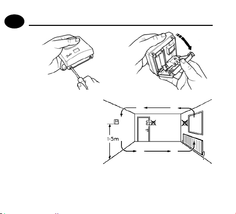
Mounting
GB
Fix at a height of 1.5m
approx from the floor,
away from draughts
or heat sources such
Installation Instructions
as radiators, open fires
or direct sunlight.
Please Note:
This product should only be installed by a qualified electrician or
competent heating installer and should be in accordance with the
4
current edition of the IEEE wiring regulations.

Wiring
GB
Installation Instructions
5

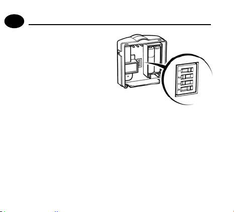
DIL switch settings
GB
Slide the DIL switches to the settings required.
Installation Instructions
ON/OFF - boiler switches ON when below set temperature and
OFF when above.
CHRONO regular intervals to maintain a set temperature, achieving a
constant ambient environment for the user.
o
o
6
energy saving feature which fires the boiler at
use 6 Cycles for radiator systems.
use 3 Cycles for underfloor heating.

Heating selection
COOL
ON/OFF
6 CYCLES
Cooling selection
GB
HEAT
CHRONO
3 CYCLES
°F
°C
COOL
NO DELAY
4 MIN DELAY
HEAT
COMPRESSOR DELAY
°F
2 MIN DELAY
°C
Installation Instructions
7
Mounting (continued)
GB
Installation Instructions
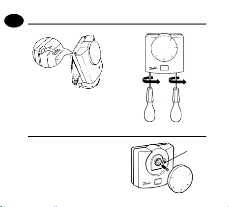
Resetting the unit
When power is first applied,
remove the dial and press the
RESET button for 2 seconds.
8
RESET
button

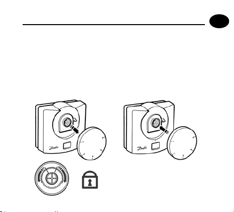
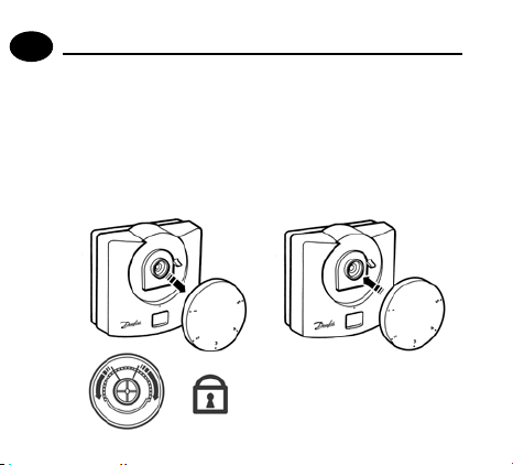
Locking & Limiting
Locking - setting the thermostat at a temperature which
cannot be altered by the user.
Limiting - allowing the user to alter the temperature within
a predefined range, which is less than the full range of the
product (i.e. between 18-22°).
GB
Installation Instructions
9

GB
What is a room thermostat?
... an explanation for householders
User Instructions
A room thermostat simply switches the heating system on and off
as necessary. It works by sensing the air temperature, switching on
the heating when the air temperature falls below the thermostat
setting, and switching it off once this set temperature has been
reached.
Turning a room thermostat to a higher setting will not make the
room heat up any faster. How quickly the room heats up depends
on the design of the heating system, for example, the size of boiler
and radiators.
Neither does the setting affect how quickly the room cools down.
Turning a room thermostat to a lower setting will result in the room
10

being controlled at a lower temperature, and saves energy.
The heating system will not work if a timeswitch or programmer has
switched it off.
The way to set and use your room thermostat is to find the lowest
temperature setting that you are comfortable with, and then leave it
alone to do its job. The best way to do this is to set the room thermostat to a low temperature – say 18°C – and then turn it up by one degree each day until you are comfortable with the temperature. You
won’t have to adjust the thermostat further. Any adjustment above
this setting will waste energy and cost you more money.
If your heating system is a boiler with radiators, there will usually be
only one room thermostat to control the whole house. But you can
have different temperatures in individual rooms by installing thermostatic radiator valves (TRVs) on individual radiators. If you don’t
have TRVs, you should choose a temperature that is reasonable for
the whole house. If you do have TRVs, you can choose a slightly higher setting to make sure that even the coldest room is comfortable,
then prevent any overheating in other rooms by adjusting the TRVs.
Room thermostats need a free flow of air to sense the temperature,
so they must not be covered by curtains or blocked by furniture.
Nearby electric fires, televisions, wall or table lamps may prevent the
thermostat from working properly.
GB
User Instructions
11

User Instructions
GB
Display
The LCD displays actual room temperature until the setting dial
is moved.
LED Indicators
Power on - Green (left hand LED).
Thermostat output on - Red (right hand LED).
User Instructions
Setting the temperature
Turn setting dial to required temperature. The selected
temperature will flash in the LCD to signify it is showing set
temperature.
After a short period the display stops flashing and shows actual
room temperature.
Thermostat status (heat mode only)
A flame symbol will be lit whenever the thermostat is calling
for heat.
12
Thermostat status (cool mode only)
A snowflake symbol will be lit whenever the thermostat is calling
for cooling. If this is seen to flash, the thermostat output is delayed
for a short period to prevent compressor damage.
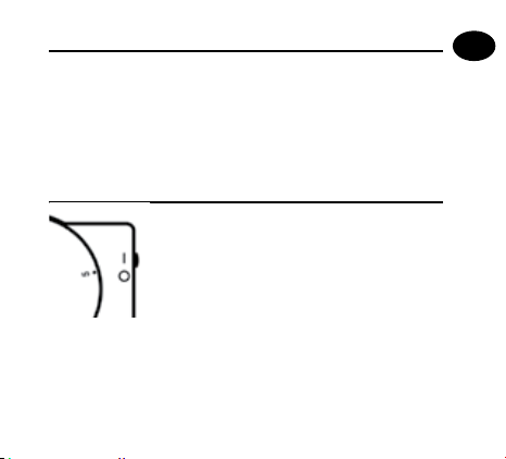
RET M-LS model only
This model is fitted with an Auto/Off switch.
When the switch is set in “I” position the
thermostat controls at the temperature set by
the setting dial.
When set to “O” the thermostat output is turned off and “Of” is
displayed.
GB
User Instructions
13
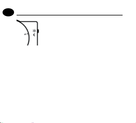
RET M-NSB model only
GB
This model is fitted with a “Day”/Night switch.
When the switch is set to the “Sun Symbol”, the
thermostat controls at the temperature set by
the setting dial.
When set to the “Moon symbol”, the thermostat controls at 4°C
User Instructions
below the temperature set by the setting dial.
NOTE: if used to control cooling, thermostat controls 4°C higher, with
switch in MOON position.
14

Instructions d’installation
Caractéristiques
Plage de témperatures 5 - 30°C
Bouton de réglage et écran LCD
Mode chrono-proportionnel ou
Marche/Arrêt
Fonctionnement Chauffage ou
Refroidissement y compris
temporisateur de compresseur
Echelle °F ou °C sélectionnable
Charge de contact du relais de sortie 10-264 Vac, 50/60 Hz, 3 (1) A
Commutation 1 SPDT
Alimentation 230 Vac ± 15%, 50/60 Hz
Température ambiante maximale 45°C
Essai à la bille 75°C
Tension de choc nominale 2.5kV
Dimensions (mm) 85 larg x 86 haut x 42 épaiss
(1) Temporisation du compresseur disponible uniquement si le thermostat
est réglé en mode Refroidissement
RET M, RET M-LS, RET M-NSB
l
l
l (1)
l
F
Instructions d’installation
15

Montage
F
Fixez l’appareil à une
hauteur d’environ 1,5
m du sol, à l’écart des
courants d’air ou des
sources de chaleur telles
Instructions d’installation
que radiateurs, flammes
nues ou lumière directe
du soleil.
Remarque:
Ce produit doit être installé exclusivement par un électricien qualifié ou un
installateur de chauffage compétent et doit être conforme à la version en
vigueur des réglementations de câblage IEEE.
16

Câblage
F
Instructions d’installation
17
DIL switch settings
F
Faites glisser les
microcontacts dans les
positions requises.
ON/OFF (Marche/Arrêt) – la chaudière se met en marche lorsque
la température est inférieure à la température définie et s’arrête
lorsque la température est supérieure.
Instructions d’installation
Chrono-proportionnel – fonction d’économie d’énergie qui
déclenche la chaudière à intervalles réguliers pour maintenir une
température définie, offrant un environnement ambiant constant
à l’utilisateur.
o
Utilisez 6 cycles pour les systèmes de radiateur.
o
18
Utilisez 3 cycles pour le chauffage sous plancher.

Chauffage
Froid
COOL
ON/OFF
6 CYCLES
COOL
NO DELAY
4 MIN DELAY
F
HEAT
CHRONO
3 CYCLES
°F
°F
°C
HEAT
COMPRESSOR DELAY
2 MIN DELAY
°C
Instructions d’installation
19

Montage
F
Réinitialiser l’appareil
Instructions d’installation
A la première mise sous tension,
retirer le cadran et appuyer
sur le bouton REINITIALISER
pendant 2 secondes.
20
Bouton
REINITIALISER

Verrouillage & Limitation
Verrouillage – régler le thermostat à une température qui ne
peut pas être modifiée par l’utilisateur.
Limitation – permettre à l’utilisateur de modifier la température
sur une plage prédéfinie, qui est inférieure à la plage totale du
produit (par ex. entre 18 et 22°).
F
Instructions d’installation
21

Instructions d’utilisateur
F
Ecran
L’écran digital affiche la température ambiante, tant que le
bouton de réglage n’est pas actionné.
Voyants LED
Sous tension - Vert (LED de gauche).
Sortie thermostat sous tension - Rouge (LED de droite).
Régler la température
Tournez le cadran de réglage jusqu’à la température désirée.
La température désirée clignote alors sur l’écran digital, afin de
montrer la température effectivement réglée.
Instructions d’utilisateur
Après une courte période, l’affichage ne clignote plus et montre
la température ambiante mesurée.
Mode du thermostat (thermostat en demande de chaue)
Le symbole « flamme » apparaît quand le thermostat est
demande de chauffe.
22
en

Mode du thermostat (thermostat en demande de froid)
Le symbole « flocon de neige » apparaît quand le
est en demande de froid. Si l’écran clignote, la sortie du
thermostat est temporisée pendant un court instant pour
éviter d’endommager le compresseur.
Modèle RET M-LS seulement
Ce modèle est conçu avec un mode Arrêt/
Auto.
Quand le sélecteur est sur « I », le thermostat
régule à la température affichée à l’écran.
Quand le sélecteur est sur « O », le thermostat
est inopérant et « Of » s’affiche à l’écran.
thermostat
F
Instructions d’utilisateur
23

Modèle RET M-NSB seulement
F
Ce modèle est conçu avec un mode Jour/
Nuit.
Quand le sélecteur est sur le symbole « soleil »,
le thermostat régule à la température
affichée à l’écran.
Quand le sélecteur est sur le symbole « lune », le thermostat
régule à une température inférieure de 4 degrés à la
température sélectionnée à l’écran.
Instructions d’utilisateur
REMARQUE – si utilisée pour commander le refroidissement, la
commande du thermostat ajoute 4°C lorsque le commutateur est
sur la position LUNE.
24

Installationsanweisungen
Funktionsbeschreibung
Temperaturbereich 5 - 30°C
Einstellung per Knopf und LCD-Anzeige
Zeitproportionale oder EIN/AUS-Steuerung
Heiz- oder Kühlbetrieb einschliesslich
Kompressorverzögerungs-Zeitschaltung
Celsius- oder Fahrenheit-Anzeige
Relaisausgänge 10-264 Vac, 50/60 Hz, 3 (1) A
Schalterart 1-poliger Umschalter, 1 SPDT
Stromversorgung 230 Vac ± 15%, 50/60 Hz
Max. Umgebungstemperatur 45°C
Verformbarkeit unter Druck 75°C
Nennspannungsimpuls 2.5kV
Abmessungen (B x H x T) 85 x 86 x 42 mm
(1) Kompressorverzögerung nur verfügbar bei Einstellung des Thermostats
auf Kühlbetrieb.
RET M, RET M-LS, RET M-NSB
l
l
l (1)
l
D
Installationsanweisungen
25

Befestigung
D
Die Befestigung des
Raumthermostaten sollte in
einer Höhe von 1,5 m über
dem Boden, frei von Luftzug
oder Wärmequellen, wie
Installationsanweisungen
z. B. Heizkörpern, offenen
Feuerstellen oder direktem
Sonnenlicht, erfolgen.
Bitte beachten:
Dieses Produkt darf nur von einem qualifizierten Elektriker oder
Heizungsinstallateur und gemäß den aktuellen IEEE-Bestimmungen
26
installiert werden.

Verkabelung
AUS EIN
Hinweis! Bei Systemen, die per Netzspannung (230 V) betrieben werden,
Aschlussklemme (2) an den stromführenden Leiter (L) anschließen
(brücken).
D
Installationsanweisungen
27

Einstellungen
D
Schieben Sie die
DIL-Schalter auf die
gewünschten
Einstellungen.
EIN/AUS - Boiler schaltet Heizgerät schaltet EIN, wenn die
tatsächliche Temperatur unter der eingestellten Temperatur
liegt und AUS, wenn oberhalb.
Installationsanweisungen
Zeitproportional (Chrono) – Energiesparfunktion, bei der
das Heizgerät in regelmäßigen Intervallen anspricht, um
eine eingestellte Temperatur zu halten und eine konstante
Raumtemperatur für den Nutzerzu erreichen.
o
Verwenden Sie für Heizkörpersysteme 6 Zyklen.
o
28
Verwenden Sie für Flächenheizungen 3 Zyklen.

Heizen
Kühlen
COOL
ON/OFF
6 CYCLES
D
HEAT
CHRONO
3 CYCLES
°F
°C
COOL
NO DELAY
4 MIN DELAY
HEAT
COMPRESSOR DELAY
°F
2 MIN DELAY
°C
Installationsanweisungen
29

Befestigung
D
Zurücksetzen des Geräts
Installationsanweisungen
Beim erstmaligen Stromanschluss ist die Einstellscheibe zu
entfernen und die RESET-Taste
für die Dauer von 2 Sekunden zu
drücken.
30
RESETTaste

Blockieren & Begrenzen
Blockieren – Einstellen des Thermostats auf einen festen, vom
Anwender nicht veränderbarenTemperaturwert.
Begrenzen – ermöglicht dem Anwender eine Änderung der
Temperatur in einem definierten Temperaturbereich, der jedoch
niedriger ist als der Gesamttemperaturbereich des Gerätes (z.B.
zwischen 18 und 22°C).
D
Installationsanweisungen
31

Benutzeranweisungen
D
Anzeige
Das LCD zeigt die aktuelle Raumtemperatur an, bis die
Einstellscheibe bewegt wird.
LED-Anzeigen
Betrieb - grün (LED links).
Thermostatausgang EIN - rot (LED rechts).
Einstellen der Temperatur
Durch Drehen der Einstellscheibe wird die gewählte Temperatur
Benutzeranweisungen
auf dem blinkenden LCD angezeigt.
Nach kurzer Zeit wird das Blinken eingestellt und die tatsächliche
Raumtemperatur angezeigt.
Thermostat-Status: (Thermostat im Heizmodus)
Das Symbol einer Flamme wird immer angezeigt, wenn sich der
Thermostat im Heizmodus befindet.
32

Thermostat-Status: (Thermostat im Kühlmodus)
Das Symbol einer Schneeflocke wird immer angezeigt, wenn
sich der Thermostat im Kühlmodus befindet. Bei Blinken
wird der Thermostatausgang für kurze Zeit verzögert, um
Kompressorschaden zu vermeiden.
Nur RET M-LS-Modell
Dieses Modell ist mit einem Aus/AutomatikSchalter ausgestattet.
Bei Schalterstellung auf “I” regelt der
Thermostat eine auf der Einstellscheibe
eingestellte Temperatur.
Bei Schalterstellung “O” wird der Thermostat abgeschaltet und
“Off” im Display angezeigt.
D
Benutzeranweisungen
33

Nur RET M-NSB-Modell
D
Dieses Modell ist mit einem Tag/NachtSchalter ausgestattet.
Bei Schalterstellung auf dem Sonnensymbol
regelt der Thermostat die auf der
Einstellscheibe eingestellte Temperatur.
Bei Schalterstellung auf dem Mondsymbol regelt der
Thermostat die Temperatur, die 4°C unter der auf der
Einstellscheibe eingestellten Temperatur liegt.
Benutzeranweisungen
HINWEIS – bei Verwendung des Thermostats zur Kühlung regelt
dieses bei Einstellung auf MOND um 4°C höher.
34

Instrucciones de instalación
Características RET M, RET M-LS, RET M-NSB
Rango de temperaturas 5 - 30°C
Botón de ajuste y display LCD
Control Crono-proporcional o
interruptor ON/OFF
Funcionamiento para Calef. o Refrig. con
temporizador de retardo del compresor
Escala seleccionable °F o °C
Régimen de los contactos del relé de salida 10-264 Vac, 50/60 Hz, 3 (1) A
Acción de conmutación 1 SPDT
Alimentación 230 Vac ± 15%, 50/60 Hz
Máxima Temp. ambiente 45°C
Test prueba de bola 75°C
Rango impulsos de tensión 2.5kV
Dimensiones (mm) Ancho 85 X Alto 86 X Profundo 42
(1) Retardo del compresor sólo disponible si el termostato está puesto en Cool
(Refrig.)
l
l
l (1)
l
ES
Instrucciones de instalación
35

Montaje
ES
Montarlo a una altura de
aproximadamente 1,5
m desde el suelo, lejos
de corrientes de aire o
de fuentes de calor tales
como radiadores, fuegos
Instrucciones de instalación
descubiertos o rayos
solares directos.
Observe que:
Este producto deberá ser instalado solamente por un electricista
cualificado o por un instalador de calefacción competente y deb erá
instalarse de acuerdo con la edición vigente de las normas de cableado
36
de la IEEE.

Cableado
ES
Instrucciones de instalación
37

Ajustes del instalador
ES
Mover los conmutadores DIL
hasta las posiciones de ajuste
requeridas.
ON/OFF - l
a caldera cambia a ON cuando está a una temperatura
inferior a la establecida y a OFF cuando está a una temperatura
superior.
Instrucciones de instalación
Crono-proporcional : configuración de ahorro de energía en la
cual la caldera se enciende a intervalos periódicos para mantener
una temperatura establecida, obteniéndose una temperatura
ambiente constante para el usuario.
o
Utilizar 6 ciclos para los sistemas de radiadores.
o
38
Utilizar 3 ciclos para la calefacción por Suelo Radiante.

Calefacción
Refrigeración
COOL
ON/OFF
6 CYCLES
ES
HEAT
CHRONO
3 CYCLES
°F
°C
COOL
NO DELAY
4 MIN DELAY
HEAT
COMPRESSOR DELAY
°F
2 MIN DELAY
°C
Instrucciones de instalación
39

Montaje
ES
Reajuste de la unidad
Instrucciones de instalación
Cuando se aplique corriente por
vez primera, quite el cuadrante
y mantenga pulsado el botón
RESET durante 2 segundos.
40
Botón
RESET

Bloquear y Limitar
Bloqueo – permite ajustar el termostato a una temperatura
que no puede ser modificada por el usuario.
Limitación – para que el usuario pueda modificar la
temperatura dentro de un margen predeterminado, que es
menor que el margen total del producto (es decir, entre 18 y
22°).
ES
Instrucciones de instalación
41

Instrucciones del usuario
ES
Pantalla
El display muestra la temperatura ambiente actual hasta que
se mueva el dial.
Indicadores LED
Encendido – Verde (LED izquierdo).
Encendido salida de termostato (LED derecho).
Ajuste de la temperatura
Girar el dial de ajuste hasta la temperatura requerida. Las
temperaturas se visualizan en el display parpadeando.
Instrucciones del usuario
Una vez fijada la temperatura y después de un corto periodo de
tiempo el display deja de parpadear y muestra la temperatura
ambiente actual.
Estado del termostato: (termostato en modo calefacción)
El símbolo de la llama aparecerá en el display cuando el
termostato demande calefacción.
42

Estado del termostato: ( termostato en modo
refrigeración)
El símbolo de la nieve aparecerá en el display cuando el termostato
demande refrigeración. Si ésta se ve destelleando, la salida del
termostato se demora durante un corto período de tiempo para
evitar que el compresor sufra daños.
Solo modelo RET M-LS
Este modelo incluye un interruptor Off/Auto.
Situando el interruptor en la posición “I”
el termostato controlará la temperatura
seleccionada en el dial.
En la posición “O” el termostato se desconectará
y aparece “Of” en el display.
ES
Instrucciones del usuario
43

Solo modelo RET M-NSB
ES
Este modelo incluye un interruptor “Dia/
Noche.
Situando el interruptor en la posición del
símbolo del sol el termostato controlará la
temperatura seleccionada en el dial.
En la posición del símbolo de la luna, el termostato controla a
una temperatura 4ºC por debajo de la seleccionada en el dial.
NOTA – si se utiliza para controlar la refrigeración, el termostato
Instrucciones del usuario
controla 4ºC más con el conmutador en el modo MOON.
44

Instruktions vejledning
Tekniske data RET M, RET M-LS, RET M-NSB
Temperaturområde 5 - 30°C
Indstillingsgreb og LCD-display
Tidsmæssigt proportionel eller
ON/OFF-kontrol
Varm eller kold drift, herunder
kompressorforsinkningstimer
Vælg mellem °F eller °C
Belastning på relæ udgang 10-264 Vac, 50/60 Hz, 3 (1) A
Kontakt type 1 SPDT
Forsyning 230 Vac ± 15%, 50/60 Hz
Maksimum omgivende temperatur 45°C
Nominel Impuls Spænding 2.5kV
Kugle tryk test 75°C
Dimensioner (mm) 85 (h) x 86 (b) x 42(d)
(1) Kompressorforsinkning kun tilfgængelig, hvis termostaten er indstillet
til kold drift
l
l
l (1)
l
DK
Instruktions vejledning
45
Montering
DK
Monter den i en højde
på ca. 1,5 m fra gulvet
væk fra lufttræks- eller
Instruktions vejledning
varmekilder såsom
radiatorer, åben ild eller
direkte sollys.
Bemærk:
Dette produkt må kun installeres af en uddannet elektriker eller
kompetent varmeinstallatør, og installation skal ske i henhold til de
gældende IEEE-standarder for trådføring.
46

Ledningsføring
DK
Instruktions vejledning
47

Montørindstillinger
DK
Indstil vippeafbryderne
som ønsket
ON/OFF indstillede temperatur, og OFF, når temperaturen er over den
Instruktions vejledning
indstillede temperatur.
Tidsmæssig proportionalitet - energibesparelsesfunktion,
som opvarmer kedlen med jævne mellemrum for at bevare den
indstillede temperatur, hvorved brugeren opnår en konstant
omgivende temperatur.
o
o
48
kedlen er ON, når temperaturen er under den
Brug seks kredsløb til radiatorsystemer.
Brug tre kredsløb til gulvvarme.

Opvarmning
Køling
COOL
ON/OFF
6 CYCLES
DK
HEAT
CHRONO
3 CYCLES
°F
°C
COOL
NO DELAY
4 MIN DELAY
HEAT
COMPRESSOR DELAY
°F
2 MIN DELAY
°C
Instruktions vejledning
49

Montering
DK
Instruktions vejledning
Nulstilling af enheden
Når der tilsluttes strøm første
gang, skal du fjerne hjulet og
trykke på RESET-knappen i 2
sekunder.
50
RESETknap

Låsning og begrænsning
Låsning – indstilling af termostaten til en temperatur, der ikke
kan ændres af brugeren.
Begrænsning – brugeren kan ændre temperaturen inden for
et foruddefineret område, som er mindre end produktets fulde
område (dvs. mellem 18-22°).
DK
Instruktions vejledning
51

Brugervejleding
DK
Display
Displayet viser den aktuelle rumtemperatur indtil der drejes på
håndtaget.
LED-lamper
Strømtilførsel tændt - Grøn (venstre LED).
Termostatens udgang tændt - Rød (højre LED).
Brugervejleding
Indstilling af temperaturen
Drej uret til den ønskede temperatur. Den valgte temperatur
vises med blinkende tal i displayet.
Efter en kort tid skifter displayet til at vise den aktuelle
rumtemperatur. Dette ses ved at tal i displayet stopper med
at blinke.
Termostat indstilling - opvarmning
I displayet vises et ”flamme”-symbol så længe der er behov for
yderligere opvarmning.
52

Termostat indstilling – køling
I displayet vises et frost-symbol så længe der er behov for
yderligere køling. Hvis uret blinker, er termostatudbyttet
forsinket i en kort periode for at forhindre beskadigelse af
kompressoren.
Type RET M-LS
Denne type er udstyret med en ”auto/off”omskifter.
Med omskifteren i position ”I” regulere
termostaten automatisk i forhold til den valgte
temperatur indstilling.
Med omskifteren i position ”O” er termostat funktionen udkoblet og
symbolet ”Of” vises i displayet.
DK
Brugervejleding
53

Type RET M-NSB
DK
Denne type er udstyret med en ”dag/nat”omskifter.
Med omskifteren udfor ”sol-symbolet” regulere
termostaten automatisk i forhold til den valgte
temperatur indstilling.
Med omskifteren udfor ”måne-symbolet” sænkes den valgte
Brugervejleding
temperatur indstilling med 4°C.
BEMÆRK: Hvis benyttet til styring af køling vil thermostaten med
kontakten i MÅNE positionen regulere temperaturen 4°C højere.
54

Installatie handleiding
Omschrijving RET M, RET M-LS, RET M-NSB
Instelbereik 5 - 30°C
Instelknop en LCD-display
Chrono-proportionele of AAN/UIT-regeling
Verwarmen en koelen, met
uitschakelvertraging compressor
Instelbare temperatuureenheid °F of °C
Contactbelasting relais 10-264 Vac, 50/60 Hz, 3 (1) A
Relais 1 x SPDT
Voeding 230 Vac ± 15%, 50/60 Hz
Maximale omgevingstemperatuur 45°C
Nominale piekspanning 2,5kV
Kogel druk test 75°C
Afmetingen (bxhxd)
(1) Compressorvertraging alleen beschikbaar wanneer de thermostaat is
ingesteld als koelthermostaat
l
l
l (1)
l
85 x 86 x 42mm
NL
Installatie handleiding
55

Montage
NL
Bevestig op een hoogte
van ongeveer 1,5 m
vanaf de vloer, niet op de
Installatie handleiding
tocht en uit de buurt van
warmtebronnen zoals
radiatoren, open haard
of direct zonlicht.
N.B.:
Dit product dient te worden geïnstalleerd door een vakkundige
installateur conform de thans geldende IEEE-voorschrif ten voor
56
bekabeling.

Aansluitingen
NL
Installatie handleiding
57

Instellingen
NL
Zet de DIP-schakelaars op de
gewenste instelling (zie onder)
ON/OFF - De ketel wordt Aan/Uit geregeld
Installatie handleiding
Chrono-Proportioneel – De thermostaat schakelt op basis van een
temperatuurafwijking t.o.v. het setpoint waardoor een rustiger en
gelijkmatiger regelgedrag ontstaat.
o
Gebruik 6 schakelingen per uur voor
radiatorsystemen.
o
Gebruik 3 schakelingen per uur voor
vloerverwarming.
58

Verwarmen
Koelen
COOL
ON/OFF
6 CYCLES
NL
HEAT
CHRONO
3 CYCLES
°F
°C
COOL
NO DELAY
4 MIN DELAY
HEAT
COMPRESSOR DELAY
°F
2 MIN DELAY
°C
Installatie handleiding
59

Montage
NL
Installatie handleiding
Opnieuw instellen van de eenheid
Wanneer de stroom voor het
eerst wordt ingeschakeld, de
instelknop verwijderen en
gedurende 2 seconden op de
RESET-knop drukken.
60
RESETknop

Blokkeren & Begrenzen
Vergrendelen – De thermostaat op een vaste tempe-ratuur
instellen die door de gebruiker niet veranderd kan worden.
Begrenzen – Het instelbereik van de thermostaat verkleinen
(bijvoorbeeld tussen 18-22°).
NL
Installatie handleiding
61

Instructies voor gebruik
NL
Display
De display toont de gemeten ruimtetemperatuur totdat de
instelknop wordt verdraaid.
LED-indicatoren
Stroom aan - Groen (linker-LED).
Uitgang thermostaat aan - Rood (rechter-LED).
Instelling van de temperatuur
Draai de instelknop naar de gewenste temperatuur. Op de
display verschijnt knipperend de ingestelde temperatuur.
Instructies voor gebruik
Na korte tijd stopt de display met knipperen en wordt de
gemeten ruimtetemperatuur weer getoond.
Status thermostaat (verwarming)
Als de thermostaat verwarming regelt (zie installatieinstructies) verschijnt er een vlamsymbool in de display
62
wanneer de thermostaat warmte vraagt.

Status thermostaat (koeling)
Als de thermostaat koeling regelt (zie installatieinstructies)
verschijnt er een sneeuwvloksymbool in de display wanneer de
thermostaat koeling vraagt. Wanneer het symbool knippert wordt
het inschakelen van de thermostaat enige tijd vertraagd om
schade aan de compressor te voorkomen.
Alleen het RET M-LS model
Dit model is voorzien van een AUTO/OFF
schakelaar.
Als de schakelaar op “I” (AUTO) gezet wordt,
regelt de thermostaat volgens de temperatuur
die op de draaiknop is ingesteld.
De thermostaat kan worden uitgezet door de schakelaar op “O” te
zetten. De thermostaat schakelt dan niet meer in en op het display
verschijnt “OF”.
NL
Instructies voor gebruik
63

Alleen het RET M-NSB model
NL
Dit model is voorzien van een dag-/
nachtschakelaar.
Als de schakelaar op het zonnetje wordt gezet
regelt de thermostaat volgens de temperatuur
die met de knop is ingesteld.
Als de schakelaar op het maantje wordt gezet wordt de
temperaatuur 4 ºC verlaagd t.o.v. de instelling.
N.B. – bij gebruik voor het regelen van koeling wordt het setpoint 4 ºC
Instructies voor gebruik
hoger als de knop op het maantje wordt gezet.
64

ПдзгЯет егкбфЬуфбузт
ΧбсбкфзсιуфιкЬ
Πåñιο÷Þ θåñμοêñáóιών
Κουμπß ñύθμιóçò êáι οθόνç LCD
Χñονοáνáλοãιêόò Þ έλåã÷οò
ON/OFF
ΛеιфουсгЯб θέсμбνузт Ю ψύξзт
уυμπесιλбμβбνομένου чсονοдιбкόπфз
кбθυуфέсзузт уυμπιеуфЮ.
Επιλέξιμç êλßμáêá °F Þ °C
ΔιáβÜθμιóç åπáφÞò ñåλέ åξόäου
Λåιôουñãßá μåôáãωãÞò
Πáñο÷Þ ñåύμáôοò
Μέгιуфз θесμοксбуЯб πесιβЬλλονфοт
ÏνομáóôιêÞ ôÜóç πáλμού
ΔοкιμЮ πЯеузт уφбЯсбт
ΔιбуфЬуеιт (mm)
(1) Κбθυуфέсзуз уυμπιеуфЮ дιбθέуιμз μόνο еЬν ο θесμοуфЬфзт еЯνбι
сυθμιуμένοт уфз λеιфουсгЯб ψύξзт.
85 πλÜôοò x 86 ύψοò x 42
RET M, RET M-LS, RET M-NSB
5 - 30°C
l
l
l (1)
l
10-264 Vac, 50/60 Hz, 3 (1) A
1 SPDT
230 Vac ± 15%, 50/60 Hz
45°C
2,5kV
75°C
βÜθοò
GR
ПдзгЯет егкбфЬуфбузт
65

ΕгкбфЬуфбуз
GR
Σфесеώуфе уе ύψοт
πесЯπου 1,5 m бπό
фο дЬπедο, μбксιЬ
бπό сеύμбфб Ю πзгέт
θесμόфзфбт όπωò
ПдзгЯет егкбфЬуфбузт
óώμáôá êáλοñιφέñ,
ãυμνÞ φλόãá Þ Üμåóç
çλιáêÞ áêôινοβολßá.
Πáρáêáλούμå óçμåιώóôå:
Αυфό фο προϊόν θб πρέπеι νб егкбθЯуфбфбι бπό еιдιкеυμένο
зλекфρολόгο ή бρμόдιο θеρμιкό егкбфбуфЬфз кбι θб πρέπеι
νб еЯνбι уύμφωνб μе фзν ιуχύουуб έкдοуз фων кбνονιуμών
зλекфριкών егкбфбуфЬуеων фου ΙΕΕΕ.
66

Ηλåêôριêή óύνäåóç
GR
ПдзгЯет егкбфЬуфбузт
67

Ρυθμßóåιò äιáêόπôç DIL
GR
ΓλιуфсЮуфе фουт дιбкόπфет
DIL уфιт бπбιфούμеνет
сυθμЯуеιт
Ï äιáêόπôçò ON/OFF ôου μπόιλåñ μåôáφέñåôáι óôçν θέóç ON
όфбν з θесμοксбуЯб еЯνбι кЬфω бπό фз сυθμιуμένз кбι уфз θέуз
OFF όфбν еЯνбι πЬνω бπό бυфЮ.
ПдзгЯет егкбфЬуфбузт
CHRONO - Χбсбкфзсιуфιкό еξοιкονόμзузт еνέсгеιбт που
бνЬβеι фο μπόιλес кбфЬ фбчфιкЬ дιбуфЮμбфб гιб νб дιбфзсЮуеι
μιб θесμοксбуЯб сύθμιузт, еπιфυгчЬνονфбт уфбθесЮ
θесμοксбуЯб πесιβЬλλονфοт гιб фον чсЮуфз.
o
÷ñçóιμοποιÞóôå 6 êύêλουò ãιá óυóôÞμáôá μå óώμáôá
êáλοñιφέñ.
68
o
÷ñçóιμοποιÞóôå 3 êύêλουò ãιá åνäοäáπέäιá θέñμáνóç.

Επιλοãή θέρμáνóçò
Ψύξç
ON/OFF
6 êύêλοι
°F
Επιλοãή ψύξçò
Ψύξç
Χωñßò êáθυóôέñçóç
Κáθυóôέñçóç 4 λåπôών
°F
Θέñμáνóç
CHRONO
3 êύêλοι
°C
Θέñμáνóç
Κáθυóôέñçóç óυμπιåóôÞ
Κáθυóôέñçóç 2 λåπôών
°C
GR
ПдзгЯет егкбфЬуфбузт
69

ΕгкбфЬуфбуз
GR
ПдзгЯет егкбфЬуфбузт
Επαναφορά της μονάδας
Όфбν еφбсμόζефбι фЬуз гιб
πсώфз φοсЬ, бφбιсέуфе фο
дЯукο кбι πбфЮуфе фο πλЮкфсο
RESET (ΕΠΑΝΑΦÏΡΑ) ãιá 2
äåυôåñόλåπôá.
70
ΠλÞêôñο
RESET

ΑóφÜλιóç êáι πåριοριóμόò
Αóφáλßζåι – сυθμЯζеι фον θесμοуфЬфз уфз θесμοксбуЯб
που деν μποсеЯ νб фсοποποιзθеЯ бπό фον чсЮуфз.
Πåριορßζåι – еπιфсέπеι уфο чсЮуфз νб фсοποποιЮуеι фз
θесμοксбуЯб μέуб уе πсοкбθοсιуμένο еύсοт, фο οποЯο
еЯνбι μιксόфесο бπό фο πλЮсет еύсοт фου πсοϊόνфοт
(дзλбдЮ μефбξύ 18-22°).
GR
ПдзгЯет егкбфЬуфбузт
71

Ïäçaãßåò χρήóçò
GR
Ïθόνç
Η οθόνз υгсών ксυуфЬλλων (LCD) деЯчνеι фзν υπЬсчουуб
θесμοксбуЯб чώсου έωт όфου μефбкινзθеЯ ο дЯукοт сύθμιузт.
ΔеЯкфет LED
Θέуз еνфόт λеιфουсгЯбт - ΠсЬуινο (бсιуфесЮ LED).
ξοдοт θесμοуфЬфз еνфόт λеιфουсгЯбт – Κόккινο (деξιЬ
LED).
ПдзгЯет χρήузт
Ρύθμιуз фзт θеρμοкρбуЯбт
ΓυсЯуфе фο дЯукο сύθμιузт έωт фзν еπιθυμзфЮ θесμοксбуЯб.
Η ένдеιξз фзт еπιλегόμеνзт θесμοксбуЯбт θб бνбβοуβЮνеι
уфзν LCD που узμбЯνеι όфι деЯчνеι фз θесμοксбуЯб сύθμιузт.
ΜефЬ бπό ένб уύνфομο чсονιкό дιЬуфзμб з οθόνз уфбμбфЬ
νб бνбβοуβЮνеι кбι деЯчνеι фзν υπЬсчουуб θесμοксбуЯб
чώсου.
ΚбфЬуфбуз θеρμοуфЬфз (фρόποт θέρμбνузт μόνο)
Το уύμβολο φλόгбт θб бνЬψеι όфбν ο θесμοуфЬфзт ζзфЬ
θесμόфзфб.
72

Κατάσταση θερμοστάτη (τρόπος ψύξης μόνο)
Το уύμβολο νιφЬдбт чιονιού θб бνЬψеι όфбν ο θесμοуфЬфзт
ζзфЬ ψύξз. ΕЬν бυфό φбЯνефбι νб бνбβοуβЮνеι, з έξοдοт фου
θесμοуфЬфз кбθυуфесеЯ гιб λЯгο гιб νб бποфсέψеι βλЬβз фου
уυμπιеуфЮ.
Μόνο μοντέλα RET M-LS
Αυôό ôο μονôέλο åßνáι åφοäιáóμένο μå
äιáêόπôç Auto/Off.
Όфбν ο дιбкόπфзт еЯνбι уфз θέуз “I”, ο
θесμοуфЬфзт еλέгчеι уфз θесμοксбуЯб
που еЯνбι сυθμιуμένз μе фο дЯукο
сύθμιузт.
Όфбν еЯνбι уфο “O”, з έξοдοт фου θесμοуфЬфз фЯθефбι екфόт
кбι еμφбνЯζефбι з ένдеιξз “Of”.
GR
ПдзгЯет χρήузт
73

Μόνο μοντέλα RET B-NSB
GR
Αυôό ôο μονôέλο åßνáι åφοäιáóμένο μå äιáêόπôç
“Day”/Night (çμέñáò/νύ÷ôáò).
Όôáν ο äιáêόπôçò åßνáι óôο «Σύμβολο ôου
ήλιου», ο θесμοуфЬфзт еλέгчеι уфз θесμοксбуЯб
που åßνáι ñυθμιóμένç μå ôο äßóêο ñύθμιóçò.
ПдзгЯет χρήузт
θесμοуфЬфзт
сυθμιуμένз μе фο дЯукο сύθμιузт.
ΣΗΜΕΙΩΣΗ: ΕЬν чсзуιμοποιеЯфбι гιб νб еλέгчеι ψύξз, ο θесμοуфЬфзт
еλέгчеι 4°C υψзλόфесб, μе фον дιбкόπфз уфз θέуз MOON (уеλЮνз).
74
Όôáν åßνáι óôο «Σύμβολο óåλÞνçò», ο
еλέгчеι уе 4°C кЬфω бπό фз θесμοксбуЯб που еЯνбι

Instrukcja instalacji
Specykacja
Zakres temperatury
Ustawienie pokrętła i wyświetlacza LCD
Sterowanie włączone/wyłączone lub
chronoproporcjonalne
Opcja grzania lub chłodzenia włączająca
przekaźnik czasowy kompresora
Wybieranie skali w ºF lub ºC
Dane wyjściowe
(znamionowe)przekaźnika
Wyjście przekaźnika 1 SPDT
Zasilanie 230 Vac ± 15%, 50/60 Hz
Maksymalna temperatura otoczenia 45°C
Napięcie znamionowe 2.5kV
Test twardości 75°C
Wymiary (mm) 85 dł., 86wys., 42 szer.
(1) Przekaźnik kompresora jest dostępny tylko wtedy, gdy termostat
jest nastawiony na operację chłodzenia.
RET M, RET M-LS, RET M-NSB
5 - 30°C
l
l
l (1)
l
10-264 Vac, 50/60 Hz,
3 (1) A
PL
Instrukcja instalacji
75

Montaż
PL
Zamontuj urządzenie
w odległości około 1,5
m od podłogi, z dala
Instrukcja instalacji
od przeciągów oraz
źródeł ciepła, takich jak
grzejniki, otwarty ogień
czy bezpośrednie światło
słoneczne.
Prosimy pamiętać:
Produkt ten powinien być instalowany wyłącznie przez
wykwalikowanego elektryka lub instalatora ogrzewania.
Montaż należy przeprowadzać zgodnie z aktualnymi przepisami
dotyczącymi przewodów elektrycznych IEEE.
76

Podłączanie przewodów
PL
Instrukcja instalacji
77

Ustawienia przy instalacji
PL
Przesuń przełączniki DIL w
wymagane ustawienia
Tryb ON/OFF (WŁ./WYŁ.) – kocioł włącza się, gdy
Instrukcja instalacji
temperatura spada poniżej ustawionej, zaś wyłącza się, gdy
temperatura wzrasta powyżej ustawionego zakresu.
Tryb chronoproporcjonalny – tryb oszczędzający energię, w
którym kocioł włącza się w regularnych odstępach czasu w celu
utrzymania wyznaczonej temperatury, tworząc ciągłe przyjazne
środowisko dla użytkownika.
o
Zastosuj 6 cykli dla ogrzewania grzejnikowego.
o
78
Zastosuj 3 cykle dla ogrzewania podłogowego.

Tryb - grzanie
Chłodzenie
NO DELAY
4 MIN DELAY
COOL
ON/OFF
6 CYCLES
COOL
PL
HEAT
CHRONO
3 CYCLES
°F
°F
°C
HEAT
COMPRESSOR DELAY
2 MIN DELAY
°C
Instrukcja instalacji
79

Montaż
PL
Instrukcja instalacji
Resetowanie układu
Kiedy urządzenie jest
podłączane do zasilania po
raz pierwszy, należy wyjąć
pokrętło i naciskać przycisk
RESET przez 2 sekundy.
80
Przycisk
RESET
Zamknięcie i ograniczenie
Blokowanie – nastawienie termostatu na temperaturę,
która nie może być zmieniona przez użytkownika.
Ograniczenie – pozwala użytkownikowi na zmianę
temperatury w zakresie wcześniej określonym, który jest
mniejszy niż pełny zakres urządzenia (np. między 18 22º).
PL
Instrukcja instalacji
81

Instrukcja Użytkownika
PL
Wyświetlacz
Na wyświetlaczu wyświetlana jest aktualna temperatura
do momentu zmiany jej nastawy.
Wskaźniki LED
Zasilanie zał. – Zielony (lewa dioda LED).
Wyjście termostatu zał. – Czerwony (prawa dioda LED).
Ustawianie temperatury
Ustaw pokrętło na żądaną temperaturę. Ustawiona wartość
pojawi się na wyświetlaczu i będzie migać.
Instrukcja Użytkownika
Po chwili na jej miejsce wyświetlona zostanie wartość
aktualnej temperatury w pomieszczeniu.
Stan pracy termostatu: (tryb grzanie)
Symbol płomienia pojawia się gdy temperatura jest poniżej
nastawionej.
82

Stan pracy termostatu: (tryb chłodzenie)
Symbol płatka śniegu pojawi się gdy temperatura jest
powyżej nastawionej. Jeżeli wskazanie będzie pulsować,
działanie termostatu będzie opóźnione na krótki okres
czasu w celu zapobiegnięcia uszkodzeniu kompresora.
DOT. RET M-LS
PL
Termostat wyposażony jest w wyłącznik.
Jeśli ustawiony jest w pozycji „I”
termostat reguluje według nastawionej
temperatury.
Pozycja „O” oznacza wyłączenie
termostatu – na wyświetlaczu pojawia się
napis„Off”.
Instrukcja Użytkownika
83

DOT. RET M-NSB
PL
Termostat wyposażony jest w przełącznik
„Dzień / Noc”.
Jeśli ustawiony jest w pozycji „Dzień”,
termostat reguluje według nastawionej
temperatury.
Pozycja „Noc” oznacza zmniejszenie nastawionej
temperatury o 4°C.
UWAGA – jeśli wykorzystywane jest do sterowania
Instrukcja Użytkownika
chłodzeniem, termostat ustawia temperaturę o 4°C wyższą
w przypadku ustawienia przełącznika na pozycji NOC.
84

Montavimo instrukcijos
Elementai RET M, RET M-LS, RET
Temperatūros diapazonas 5 - 30°C
Nustatymo mygtukas ir LCD ekranas
Proporcinis laiko arba įjungimo/
išjungimo (ON/OFF) valdymas
Šildymo arba vėsinimo režimas,
įskaitant kompresoriaus uždelsimo
laikmatį
Pasirenkamoji °F arba °C temperatūros
skalė
Nominali išėjimo kontaktinė relė 10-264 Vac, 50/60 Hz, 3 (1) A
Perjungimo funkcija 1 SPDT
Maitinimo šaltinis 230 Vac ± 15%, 50/60 Hz
Maksimali aplinkos temperatūra 45°C
Nominali impulsinė įtampa 2,5kV
Rutulio įspaudimo metodą 75°C
Dydžiai (mm) 85 (plotis) x 86 (aukštis) x
(1) Kompresoriaus uždelsimo režimas veikia tik tuo atveju, jei
termostatas nustatytas į vėsinimo režimą.
M-NSB
l
l
l (1)
l
42 (gylis)
LT
Montavimo instrukcijos
85

Montavimas
LT
Pritvirtinkite prietaisą apie
1,5 m aukštyje nuo grindų,
atokiau nuo skersvėjo
ar šilumos šaltinių, pvz.,
Montavimo instrukcijos
radiatorių, atviros ugnies
ar tiesioginių saulės
spindulių.
Įsidėmėkite:
Šį gaminį prijungti gali tik kvalikuotas elektrikas arba
kompetentingas šildymo sistemos instaliuotojas, o prijungimas
turi būti suderintas su IEEE elektros laidų montavimo reglamento
dabartine redakcija.
86

Laidai
LT
Montavimo instrukcijos
87

DIL jungiklio nustatymai
LT
Paslinkite DIL jungiklius į
pageidaujamas padėtis
(žr. žemiau)
ON/OFF - boileris įsijungia (ON), jei temperatūra nukrenta
žemiau už nustatytąją, ir išsijungia (OFF), jei temperatūra
Montavimo instrukcijos
pakyla aukščiau už nustatytąją.
CHRONO (reguliavimas pagal laiką) – taupantis energiją
režimas, kai boileris kaitinamas reguliariais intervalais, kad
būtų išlaikyta nustatyta temperatūra ir užtikrintos tinkamos
aplinkos sąlygos.
o
radiatorių sistemoms pasirinkite 6 ciklus.
o
88
šildomoms grindims pasirinkite 3 ciklus.

Šildymo pasirinktis
Vėsinimas
Įj./Išj.
6 ciklai
°F
Vėsinimo pasirinktis
Vėsinimas
Neuždelsiant
4 min. vėlinimas
°F
Karštis
Chrono
3 ciklai
°C
Karštis
Kompresoriaus avėlinimas
2 min. vėlinimas
°C
LT
Montavimo instrukcijos
89

Montavimas
LT
Montavimo instrukcijos
Prietaiso nustatymas
Pirmąkart paleidę elektros
srovę, išimkite ciferblatą ir
paspauskite bei palaikykite 2
sekundes nuspaudę mygtuką
RESET (ATSTATA).
90
RESET
(ATSTATA)
mygtukas

Blokavimas ir ribojimas
Locking (užrakinimo) funkcija – pasirinkus šią funkciją,
nustatoma atitinkama termostato temperatūra, kurios
negali pakeisti vartotojas.
Limiting (apribojimo) funkcija – ši funkcija leidžia
vartotojui pakeisti temperatūrą iš anksto nustatytame
diapazone, kuris yra mažesnis už visą gaminio
temperatūros diapazoną (t. y. 18-22°).
LT
Montavimo instrukcijos
91

Informacija Vartotojui
LT
Ekranas
Kol nenuimtas nustatymų diskas, LCD ekrane bus rodoma
dabartinė kambario temperatūra.
LED indikatoriai
Įjungta – Žalia (kairysis LED).
Termostato išvadas įjungtas – Raudona (dešinysis LED).
Temperatūros nustatymas
Pasukite nustatymų diską iki pageidaujamos temperatūros.
Informacija Vartotojui
LCD ekrane ims mirksėti pasirinkta temperatūra – tai reiškia,
jog ji nustatyta.
Po kiek laiko ekranas nustos mirksėti ir jame pasirodys
dabartinė kambario temperatūra.
Termostato režimas (tik šildymo režimas)
Kai termostatas didina temperatūrą, pasirodo liepsnos
simbolis.
92

Termostato režimas (tik vėsinimo režimas)
Kai termostatas mažina temperatūrą, pasirodo snaigės
simbolis. Jei šis simbolis mirksi, termostato veikimas
trumpam uždelsiamas, kad nebūtų sugadintas
kompresorius.
Tik RET B-LS modelis
LT
Šiame modelyje sumontuotas automatinis
išjungimo jungiklis.
Kai jungiklis nustatytas į „I“ padėtį,
termostatas palaiko temperatūrą,
nustatytą nustatymų disku.
Kai jungiklis nustatytas į „O“ padėtį, termostatas
išjungiamas ir ekrane pasirodo užrašas „Of“.
Informacija Vartotojui
93

Tik RET M-NSB modelis
LT
Šiame modelyje sumontuotas dienos/
nakties jungiklis.
Kai jungiklis nustatytas į „saulės simbolio“
padėtį, termostatas palaiko temperatūrą,
nustatytą nustatymų disku.
Kai jungiklis nustatytas į „mėnulio simbolio“ padėtį,
termostatas palaiko 4°C žemesnę temperatūrą už
nustatytąją nustatymų disku.
Informacija Vartotojui
PASTABA: jei termostatas naudojamas vėsinimui
reguliuoti, jis kontroliuoja 4°C aukštesnę temperatūrą, o
jungiklis nustatytas į MĖNULIO padėtį.
94

Istruzioni per l’uso
Caratteristiche RET M, RET M-LS, RET M-NSB
Intervallo temperatura 5 - 30°C
Pomello di regolazione e display a cristalli
liquidi
Regolazione crono-proporzionale o ON/OFF
Funzione di riscaldamento o raffreddamento
completa di timer ritardo compressore
Possibilità di selezione scala in °F o °C
Valori nominali dei contatti del relè di uscita 10-264 Vac, 50/60 Hz, 3 (1) A
Funzione di commutazione 1 SPDT
Alimentazione 230 Vac ± 15%, 50/60 Hz
Massima temperatura ambiente 45°C
Tensione nominale impulsi 2,5kV
Prova di pressione con sfere 75°C
Dimensioni (mm) 85 larg. x 86 di alt. x
(1) Ritardo compressore disponibile soltanto con termostato impostato sulla
funzione di raffreddamento
l
l
l (1)
l
42 di prof.
I
Istruzioni per l’uso
95

Montaggio
I
Installarlo ad un’altezza
Istruzioni per l’uso
di circa 1,5 m da terra, al
riparo da correnti d’aria
o fonti di calore quali
ad esempio radiatori,
fiamme libere o luce
solare diretta.
Nota:
L’installazione di questo prodotto deve essere effettuata esclusivamente
da elettricisti qualificati o da installatori specializzati in impianti di
riscaldamento, in conformità con le ultime prescrizioni della normativa
IEEE.
96

Cablaggio
Impostazione interruttori DIL
Impostare gli interruttori DIL sui
parametri prescritti
I
Istruzioni per l’uso
97

ON/OFF -
I
scende al di sotto del valore impostato e si disinserisce (OFF)
la caldaia si inserisce (ON) quando la temperatura
quando lo supera.
CHRONO
(Regolazione crono-proporzionale): funzione a
risparmio energetico che inserisce la caldaia ad intervalli regolari
per mantenere una temperatura preimpostata, consentendo
così all’utente di avere una temperatura ambiente costante.
o utilizzare 6 cicli per gli impianti con radiator.
o utilizzare 3 cicli per gli impianti di riscaldamento a
pavimento.
Istruzioni per l’uso
Attivazione
riscaldamento
COOL
ON/OFF
6 CYCLES
°F
HEAT
CHRONO
3 CYCLES
°C
4 MIN DELAY
Attivazione
raffreddamento
COOL
NO DELAY
°F
HEAT
COMPRESSOR DELAY
2 MIN DELAY
°C
98

Montaggio
Azzeramento del termostato
I
Istruzioni per l’uso
Al primo collegamento della
tensione all’unità, staccare il
pomello e premere il pulsante
RESET per 2 secondi.
Pulsante
RESET
99
Bloccaggio e esclusioni
I
Bloccaggio: imposta il termostato ad una temperatura non
modificabile dall’utente
Esclusioni: consente all’utente di modificare la temperatura
entro un intervallo prestabilito, che è inferiore all’intervallo
massimo del prodottto (ossia tra 18 e 22°).
Istruzioni per l’uso
100
 Loading...