Danfoss RET2001M, TP5001M Installation guide [da]

0 (0)
Danfoss RET2001M, TP5001M Installation guide

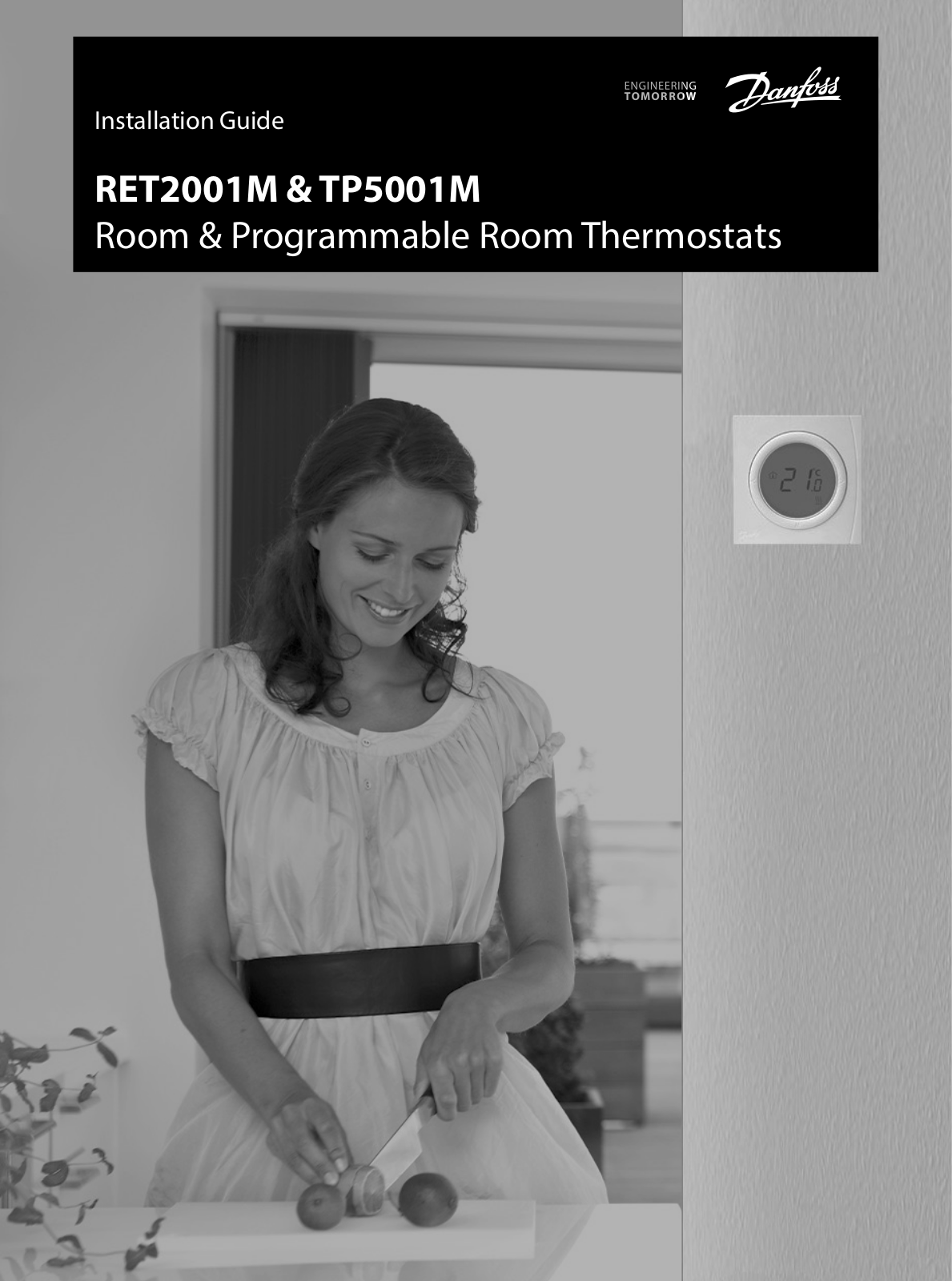
Installation Guide

RET2001M & TP5001M

Room & Programmable Room Thermostats

Installation Guide

RET2001M & TP5001M


VISUO14F

Danfoss Heating Solutions

Installation Guide

RET2001M & TP5001M


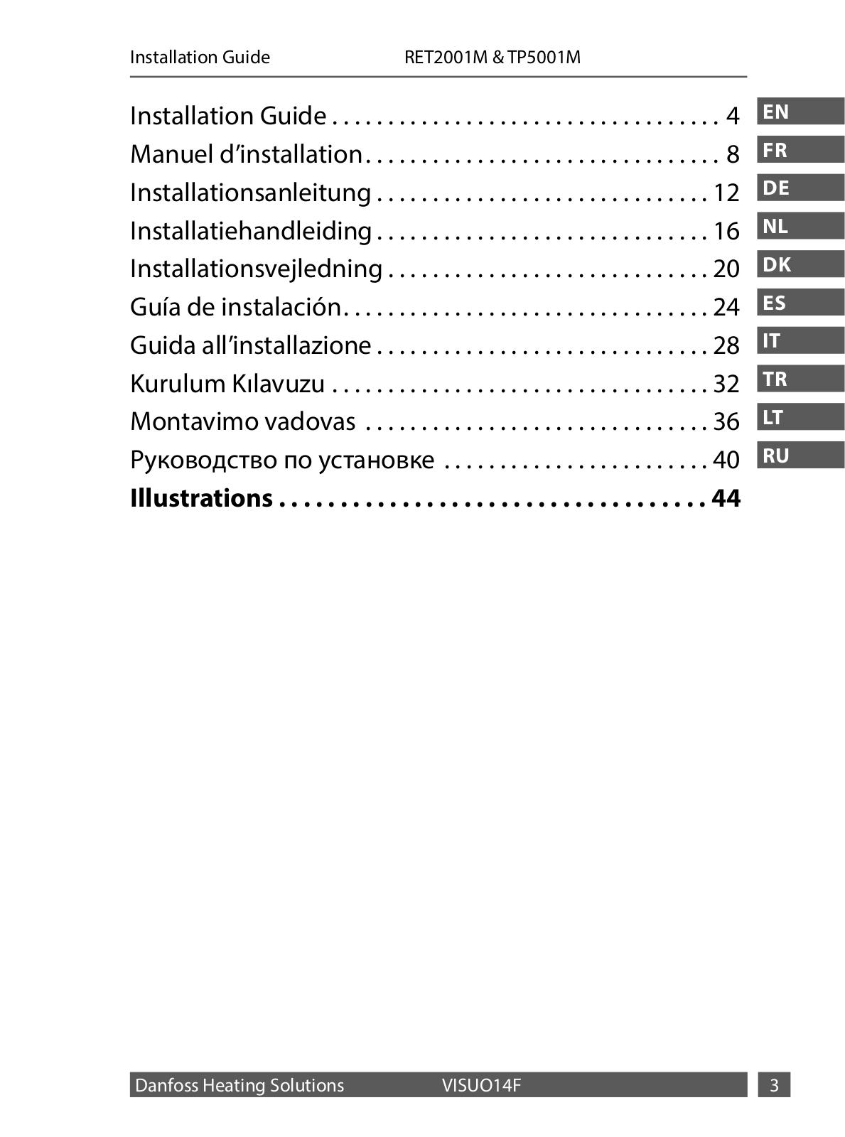
Installation Guide.. . . . . .

. . . . . . . . . . . . . . . . . . . . . . . . . . . .

. 4

Manuel d’installation. . . . .

. . . . . . . . . . . . . . . . . . . . . . . . . . .

8

Installationsanleitung.. . .

. . . . . . . . . . . . . . . . . . . . . . . . . . .

12

Installatiehandleiding.. . .

. . . . . . . . . . . . . . . . . . . . . . . . . . .

16

Installationsvejledning.. .

. . . . . . . . . . . . . . . . . . . . . . . . . . .

20

Guía de instalación. . . . . . . . .

. . . . . . . . . . . . . . . . . . . . . . . .

24

Guida all’installazione.. . .

. . . . . . . . . . . . . . . . . . . . . . . . . . .

28

Kurulum Kılavuzu.. . . . . . .

. . . . . . . . . . . . . . . . . . . . . . . . . . .

32

Montavimo vadovas .. . . .

. . . . . . . . . . . . . . . . . . . . . . . . . . .

36

Руководство по установке .. . . . . . . . . . . . . . . . . . . . . . . .

40

Illustrations. . . . . . . . . . .

. . . . . . . . . . . . . . . . . . . . . . . . .

44

EN

FR

DE

NL

DK

ES

IT

TR

LT

RU

Danfoss Heating Solutions

VISUO14F


Installation Guide

RET2001M & TP5001M


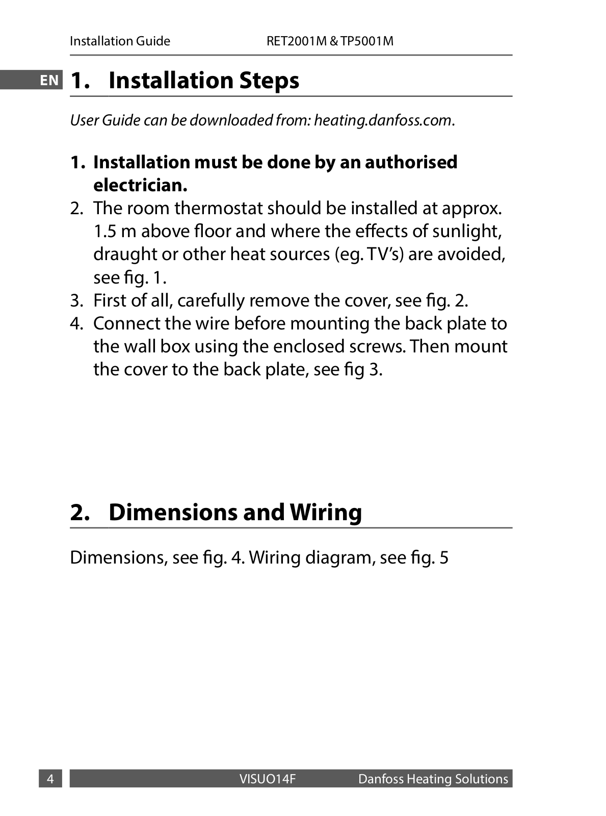
EN 1.. Installation Steps

User Guide can be downloaded from: heating.danfoss.com.

1.Installation must be done by an authorised electrician..

2.The room thermostat should be installed at approx.. 1..5 m above floor and where the effects of sunlight, draught or other heat sources (eg.. TV’s) are avoided, see fig.. 1..

3.First of all, carefully remove the cover, see fig.. 2..

4.Connect the wire before mounting the back plate to the wall box using the enclosed screws.. Then mount the cover to the back plate, see fig 3..

2.. Dimensions and Wiring

Dimensions, see fig.. 4.. Wiring diagram, see fig.. 5


VISUO14F

Danfoss Heating Solutions

Installation Guide

RET2001M & TP5001M


3.. Error codes


EN


Display

Description


E1

Sensor Failure


EE

EEPROM Failure


Lo

Measured temperature below 0 ºC


Hi

Measure temperature above 50 ºC


Danfoss Heating Solutions

VISUO14F


Installation Guide

RET2001M & TP5001M


4.. Technical Specifications


EN


Specifications


RET2001M / TP5001M


Operating Voltage


230Vac ±10% 50/60Hz


Output


Volt free


Setting temperature


5 ºC to 35 ºC


range


Operating temperature


0 ºC to 40 ºC


range


Switch rating


3A (1) at 230Vac


Switch type


1x SPDT Type 1B


IP rating


IP30 (installed)


Load compensation


Yes


control


On/off control


Yes


ErP class


Class IV, efficiency gain 2%


Construction


EN60730-2-9


Control pollution


Degree 2


situation


Rated impulse voltage


2..5kV


Ball pressure test


75 ºC


Dimensions


H86 x W86 x D43


Software classification


A


VISUO14F

Danfoss Heating Solutions


Installation Guide

RET2001M & TP5001M


EN

This product complies with the following EU Directives: Electromagnetic Compatibility

2014/30/EU Low Voltage 2014/35/EU

Restriction of the use of certain Hazardous Substances 2011/65/EU

Danfoss Heating Solutions

VISUO14F


Manuel d’installation

RET2001M & TP5001M


1.. Étapes d’installation

FR Le guide de l’utilisateur peut être téléchargé sur : heating.danfoss. com.

1.L’installation doit être réalisée par un électricien agréé..

2.Le thermostat d’ambiance doit être installé à environ 1,50 m au-dessus du sol et à l’écart du rayonnement solaire, des courants d’air et d’autres sources de chaleur ( téléviseurs, etc..) (voir fig.. 1)..

3.Commencez par enlever délicatement le couvercle (voir fig.. 2)..

4.Raccordez le fil avant de monter la plaque arrière sur le boîtier mural à l’aide des vis fournies.. Montez ensuite le couvercle sur la plaque arrière (voir fig.. 3)..

2.. Dimensions et câblage

Dimensions (voir fig.. 4) Schéma de câblage (voir fig.. 5)


VISUO14F

Danfoss Heating Solutions

Manuel d’installation RET2001M & TP5001M

3.. Codes d’erreur

FR

Écran

Description

E1

Défaillance de la sonde


EE

Défaillance de l’EEPROM

Basse

Température mesurée inférieure à 0 ºC


Haute

Température mesurée supérieure à 50 ºC

Danfoss Heating Solutions

VISUO14F


Manuel d’installation RET2001M & TP5001M

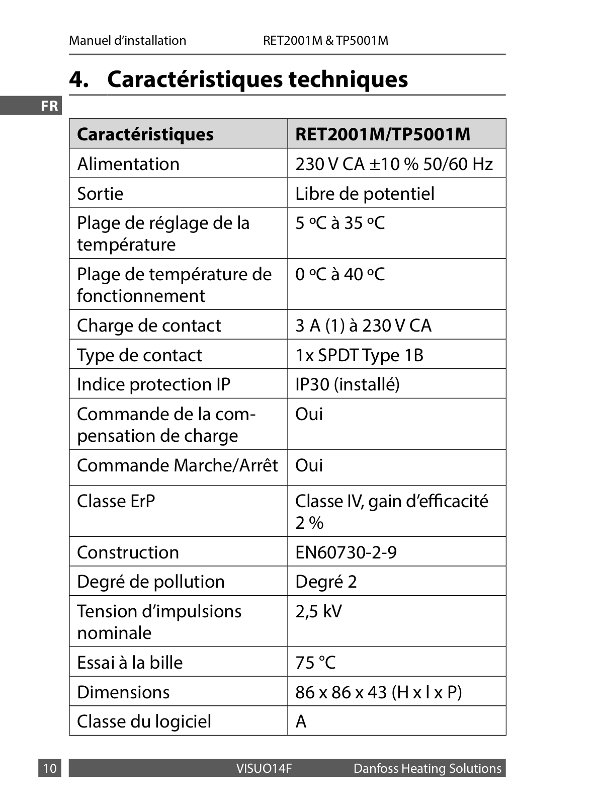
4.. Caractéristiques techniques

FR


Caractéristiques


RET2001M/TP5001M


Alimentation


230 V CA ±10 % 50/60 Hz


Sortie


Libre de potentiel


Plage de réglage de la


5 ºC à 35 ºC


température


Plage de température de


0 ºC à 40 ºC


fonctionnement


Charge de contact


3 A (1) à 230 V CA


Type de contact


1x SPDT Type 1B


Indice protection IP


IP30 (installé)


Commande de la com-


Oui


pensation de charge


Commande Marche/Arrêt


Oui


Classe ErP


Classe IV, gain d’efficacité


2 %


Construction


EN60730-2-9


Degré de pollution


Degré 2


Tension d’impulsions


2,5 kV


nominale


Essai à la bille


75 °C


Dimensions


86 x 86 x 43 (H x l x P)


Classe du logiciel


A


VISUO14F

Danfoss Heating Solutions


Manuel d’installation

RET2001M & TP5001M


Ce produit est conforme aux directives européennes suivantes :


FR

Compatibilité électromagnétique


2014/30/UE


Basse tension


2014/35/UE


Restriction sur l’usage de certaines substances dangereuses


2011/65/UE


Danfoss Heating Solutions

VISUO14F


Installationsanleitung

RET2001M & TP5001M


1.. Einbauschritte

Die Bedienungsanleitung kann unter folgender Adresse herunter- DE geladen werden: Waerme.danfoss.com.

1.Der Einbau muss durch einen autorisierten Elektriker erfolgen..

2.Der Raumthermostat sollte in ca.. 1,5 m Höhe und geschützt vor Sonneneinstrahlung, Zugluft oder anderen Wärmequellen (z.. B.. Fernsehgeräten) eingebaut werden, siehe Abb.. 1..

3.Entfernen Sie zunächst vorsichtig die Abdeckung, siehe Abb.. 2..

4.Schließen Sie den Draht an, bevor Sie die hintere Deckplatte mit den beigefügten Schrauben an das Wandkästchen montieren.. Befestigen Sie anschließend die Abdeckung an der hinteren Deckplatte, siehe Abb.. 3..

2.. Abmessungen und Verdrahtung

Abmessungen, siehe Abb.. 4.. Schaltplan, siehe Abb.. 5


VISUO14F

Danfoss Heating Solutions

Installationsanleitung

RET2001M & TP5001M


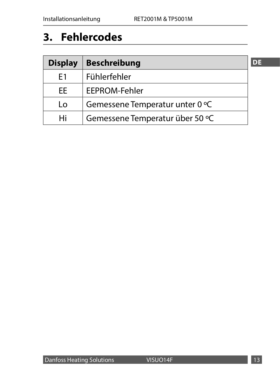
3.. Fehlercodes


Display

Beschreibung


DE


E1

Fühlerfehler


EE

EEPROM-Fehler


Lo

Gemessene Temperatur unter 0 ºC


Hi

Gemessene Temperatur über 50 ºC


Danfoss Heating Solutions

VISUO14F


Installationsanleitung

RET2001M & TP5001M


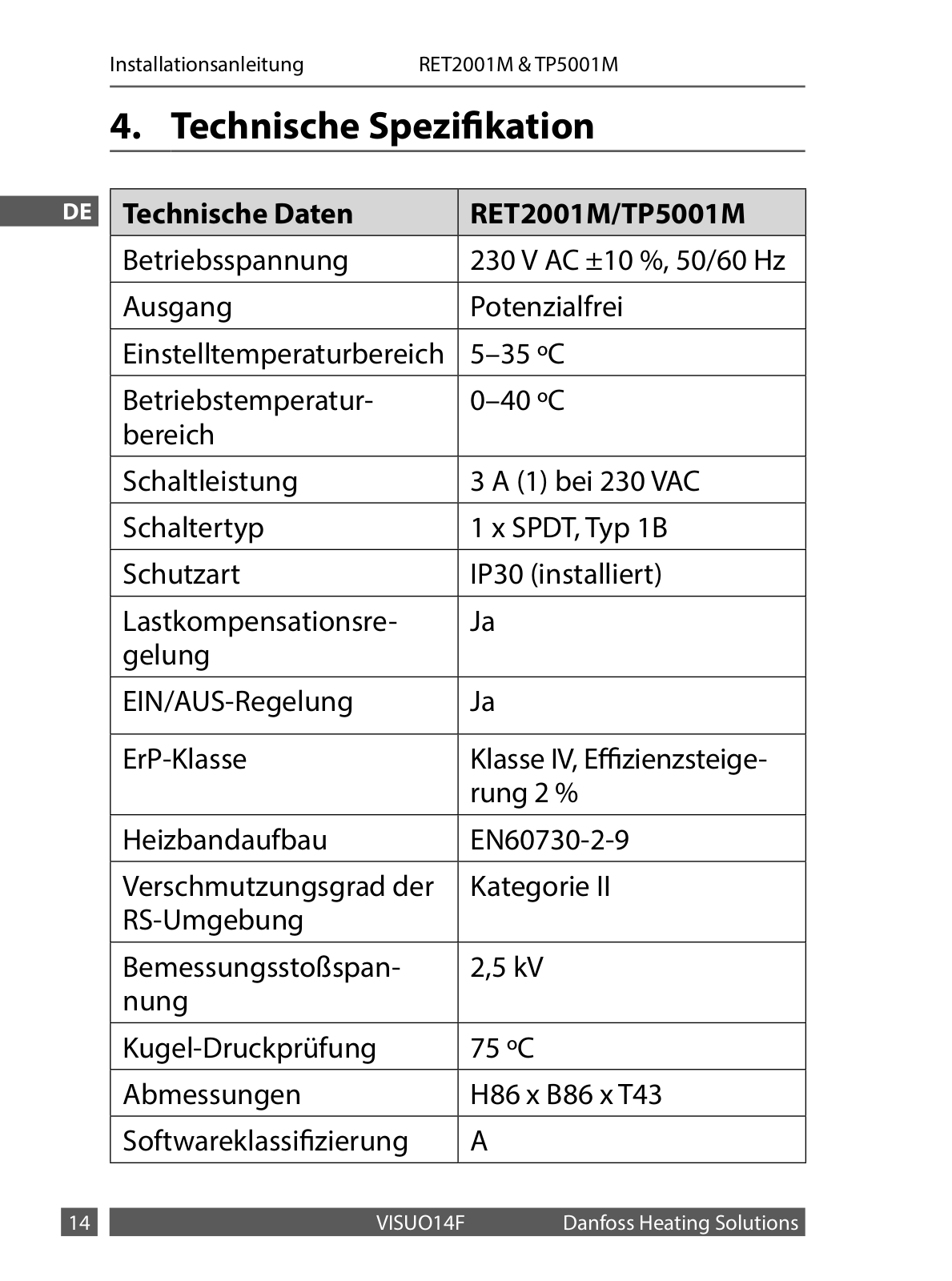
4.. Technische Spezifikation


DE


Technische Daten


RET2001M/TP5001M


Betriebsspannung


230 V AC ±10 %, 50/60 Hz


Ausgang


Potenzialfrei


Einstelltemperaturbereich


5–35 ºC


Betriebstemperatur-


0–40 ºC


bereich


Schaltleistung


3 A (1) bei 230 VAC


Schaltertyp


1 x SPDT, Typ 1B


Schutzart


IP30 (installiert)


Lastkompensationsre-


Ja


gelung


EIN/AUS-Regelung


Ja


ErP-Klasse


Klasse IV, Effizienzsteige-


rung 2 %


Heizbandaufbau


EN60730-2-9


Verschmutzungsgrad der


Kategorie II


RS-Umgebung


Bemessungsstoßspan-


2,5 kV


nung


Kugel-Druckprüfung


75 ºC


Abmessungen


H86 x B86 x T43


Softwareklassifizierung


A


VISUO14F

Danfoss Heating Solutions


Loading...
+ 32 hidden pages