

RET2000 MD
Electronic digital thermostat with LCD, delayed start
Danfoss Heating
Installation Guide
For a large print version of these instructions
please call Marketing on 0845 121 7400.
Danfoss can accept no responsibility for possible errors in catalogues, brochures, and other
printed material. All trademarks in this material are property of the respective companies.
Danfoss and the Danfoss logotype are trademarks of Danfoss A/S. All rights reserved.
2
RET2000MD
Installation Instructions
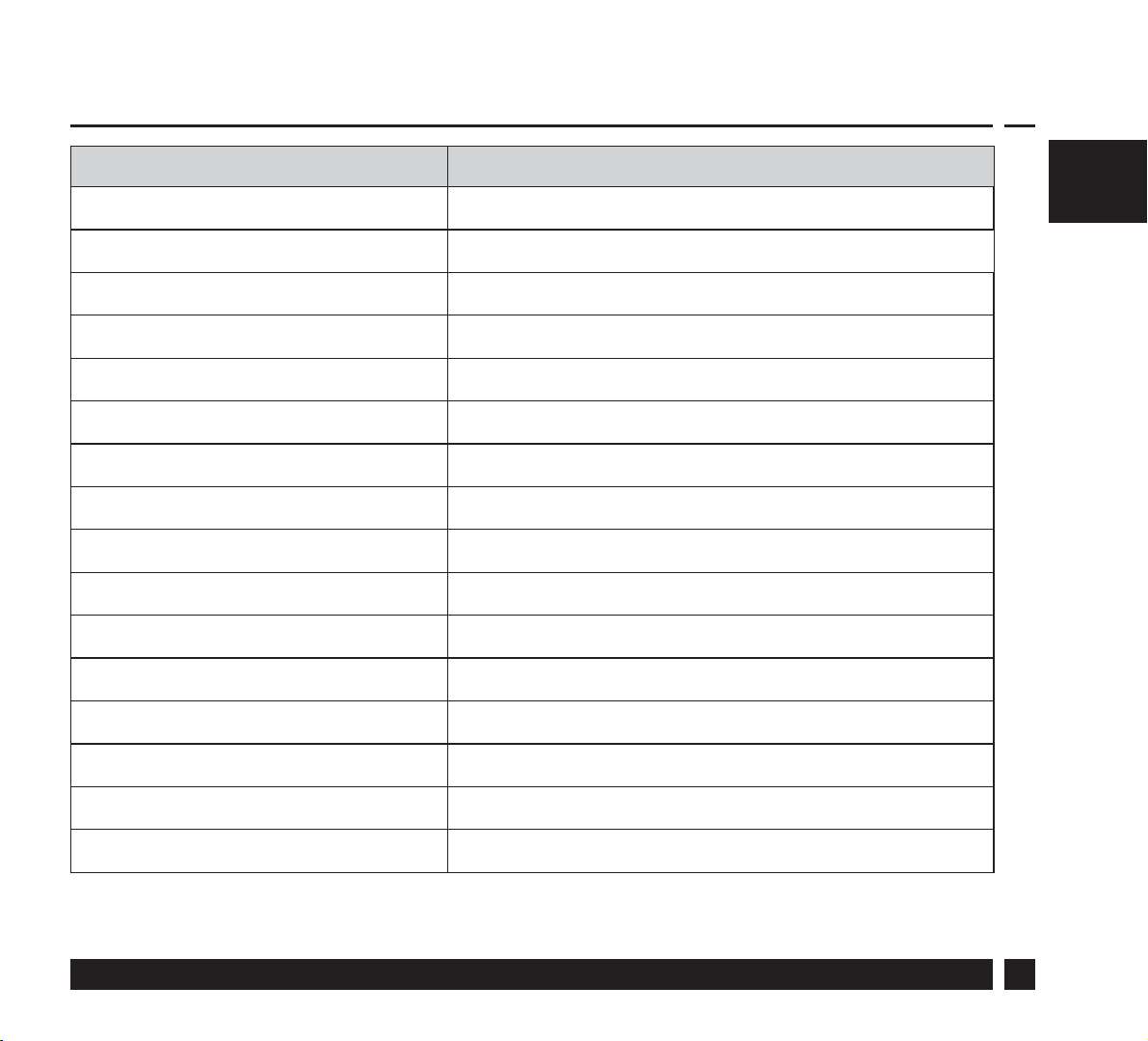
Speci cations RET2000MD
Operating Voltage 230Vac 50/60Hz
Output Volt free
Setting temp. range 5-30°C
Operating temp. range 0-45°C
Switch rating 3A (1) at 230Vac
Switch type 1 x SPDT Type 1B
IP rating IP20
On/o control Yes
Chrono-proportional control Yes
Delayed start Yes
Construction EN 60730-2-9
GBGB
Control pollution situation Degree 2
Rated impulse voltage 2.5kV
Ball pressure test 75°C
Dimensions (mm) H84 x W84 x D35
Software Classi cation A
Danfoss Heating
3
GBGB
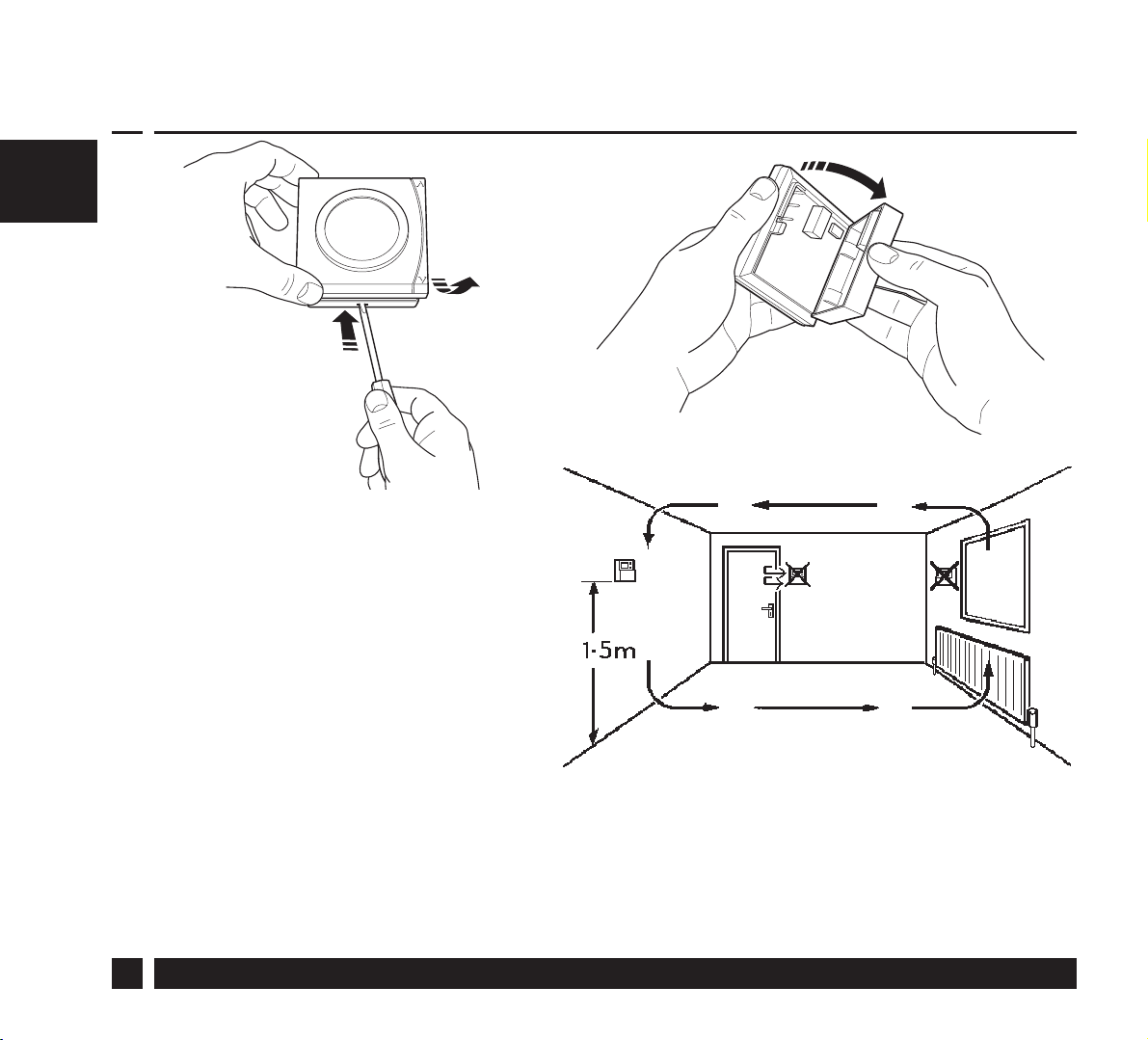
Mounting
Fix at a height of 1.5m
approx from the oor,
away from draughts
or heat sources such
as radiators, open res
or direct sunlight.
Please Note:
This product should only be installed by a quali ed electrician or
competent heating installer and should be in accordance with the
current edition of the IEEE wiring regulations.
4
RET2000MD
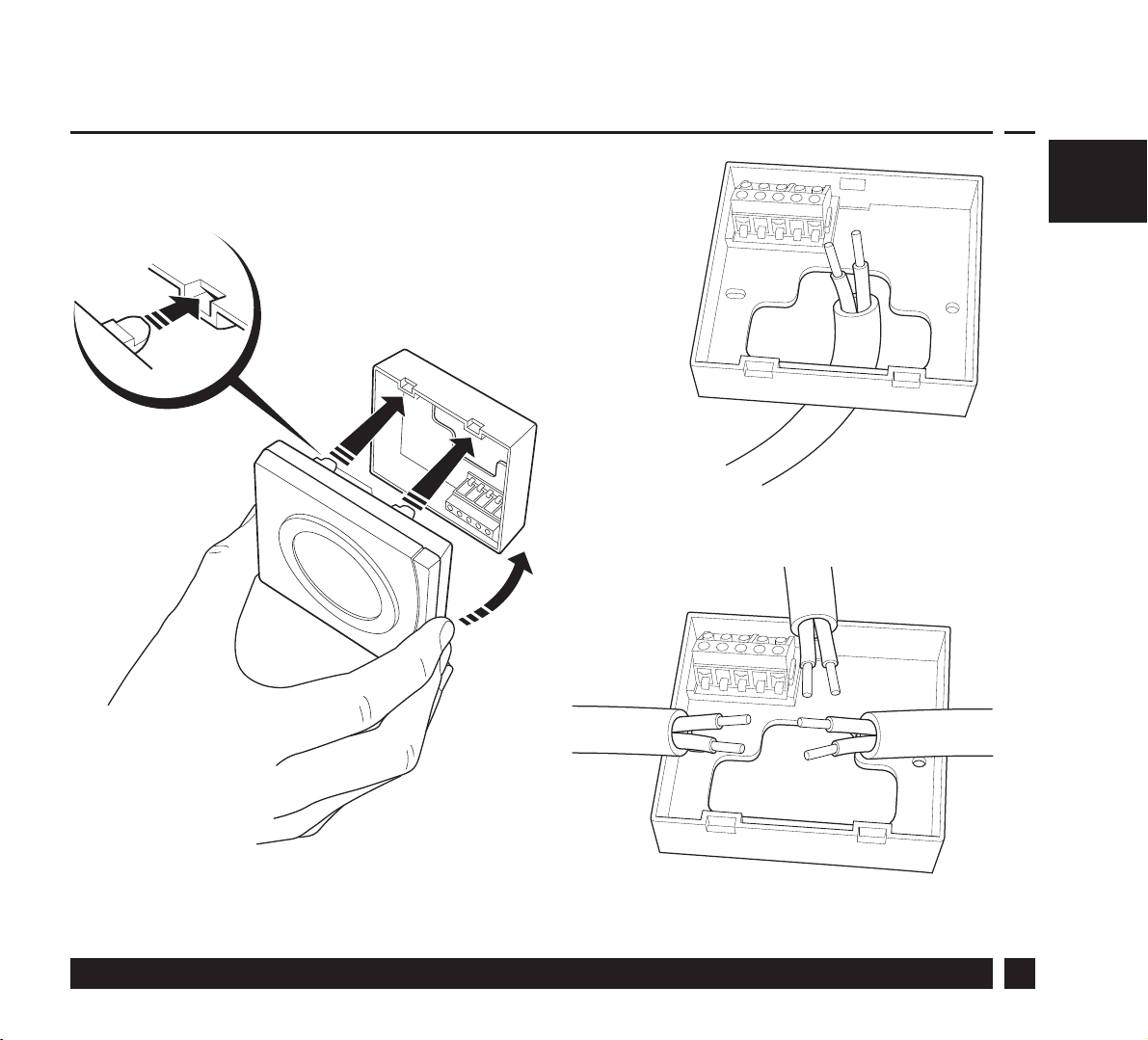
Mounting
GBGB
Danfoss Heating
5

GBGB
Wiring
RET2000MD
ELECTRONICS
N
N
230Vac
Note: For RET2000 MD live supply is from the Time Control output.
6
L
L
1
COM
2
ON
3
OFF
RET2000MD
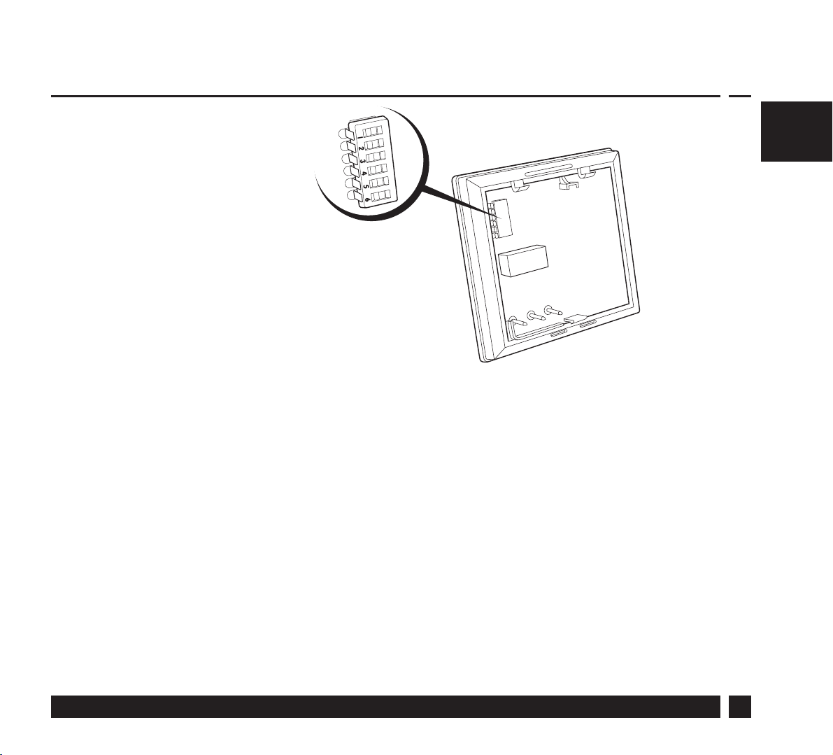
DIL switch settings
Slide the DIL switches
to the settings required.
ON/OFF - output switches ON when below set temperature and OFF
when above.
GBGB
CHRONO -
intervals to maintain a set temperature, achieving a constant
ambient environment for the user.
o
use 6 Cycles for radiator systems
o
use 3 Cycles for under oor heating
Danfoss Heating
energy saving feature which res the boiler at regular
7

DIL switch settings
GBGB
DELAYED START -
energy saving feature which automatically
delays the heating start time, depending on how close to
set-point the ambient room temperature already is (see chart
opposite). For example during milder weather the heating start
time can be delayed to avoid wasting fuel by bringing rooms
up to temperature earlier than necessary.
Delayed start only operates when switched from a timer
control.
CHRONO
6 CYCLES
3 CYCLES
ON/OFF
3/12 CYCLES
12 CYCLES
DELAYED START ON
°C
KEYS UNLOCKED
8
DELAYED START OFF
°F
KEYS LOCKED
RET2000MD

DIL Switch Settings
switch on, minutes
GBGB
Time delay after time control
Danfoss Heating
Temperature below thermostat setting, ⁰C
9

Locking and Limiting
GBGB
The RET2000 has an Advance Programming Mode in order to set
up temperature lock and limit settings.
• Press the V button until the standby mode is reached.
• The V button should then be released and then pressed
and held for a further 5 seconds to enter the Advanced
Programming Mode.
• To indicate that the unit is in Advanced Programming Mode
the Standby Indicator will ash and the display will show the
setting number alternating with the current value for that
setting.
• To change the setting press either the Λ or V button.
10
RET2000MD
• A simultaneous push and release of both buttons will scroll
through the steps S1 to S3 and will save the current set value if
altered.
• To exit Advanced Programming Mode and return to Standby
Mode press and hold both buttons for more than 5 seconds.
• While in Advanced Programming Mode if no buttons are
pressed for more than 2 minutes the unit will automatically
return to Standby mode, and the value on the current setting
will not be saved.
S1 – Lower Temperature Limit
GBGB
This setting allows for a Lower Temperature Limit to be set.
The Lower Limit can be set between 5°C (41°F) and 30°C
(86°F).
Default – 5°C/41°F
Danfoss Heating
11

S2 – Upper Temperature Limit
This setting allows for a Upper Temperature Limit to be set.
GBGB
The Upper Limit can be set between 5°C (41°F) and
30°C (86°F). However, this will be limited by the Lower
Temperature Limit set in S1 therefore the Upper Temperature
Limit cannot be less than the Lower Temperature Limit.
Default – 30°C/86°F
S3 – Set Point Power-Up Temperature
This setting de nes the set point at power up when Button
Lock is enabled on the DIL switch.
This can be set between the Lower and Upper Temperature
Limits set in S1 and S2.
Default – 21°C/70°F
12
RET2000MD

GBGB
Danfoss Heating
13

GB
14
RET2000MD

GB
Danfoss Heating
15

Danfoss Ltd
Ampthill Road
Bedford MK42 9ER
Tel: 01234 364621
Fax: 01234 219705
Email: ukheating@danfoss.com
Website: www.heating.danfoss.co.uk
Part No 44076v01 03/15
VIJTD102
 Loading...