

Page 1
Instructions
REG 15 - 65
REG-SS 15-40
148R9531
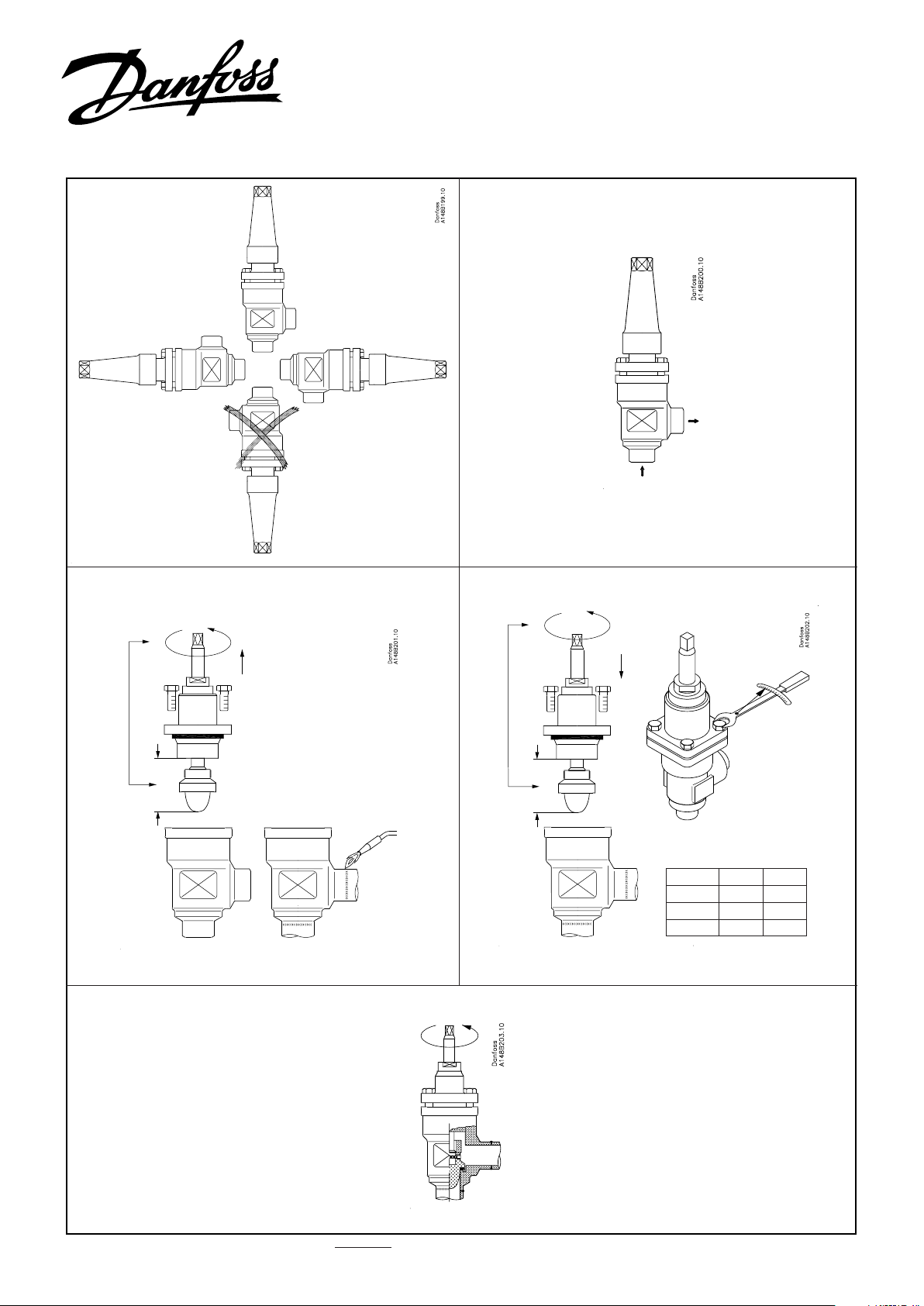
Fig. 1 Fig. 2
(PS 52 bar / 754 psi)
148R9531
Nm LB-feet
DN 15-25 22 16
DN 25-50 44 32
DN 65 75 53
Fig. 3 Fig. 4
Fig. 5
© Danfoss A/S (AC-SMC/MWA), 06-2010 RI1GC102 DKRCI.PI.KM0.C1.02 / 520H4511 1
Page 2
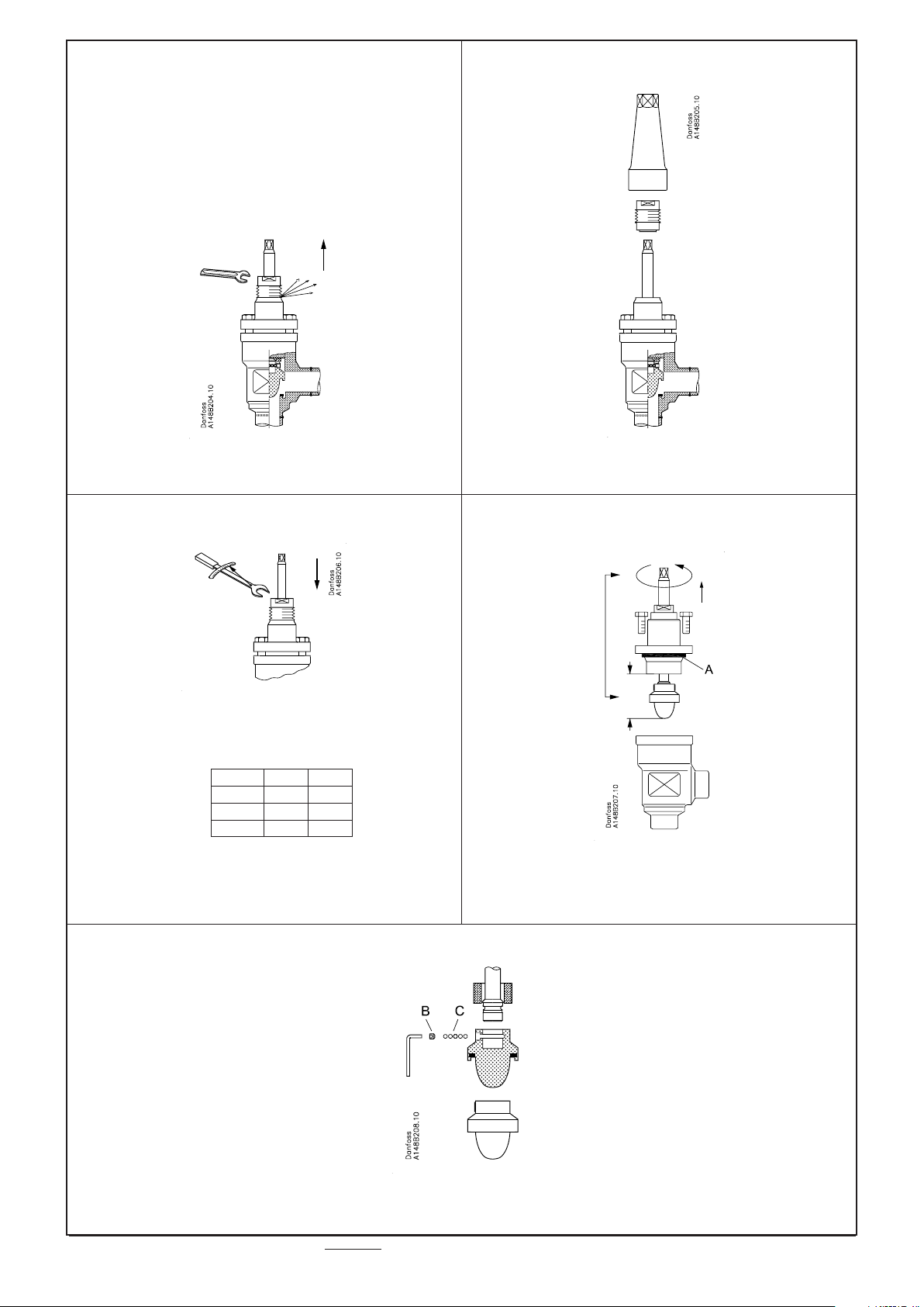
Fig. 6
Nm LB-feet
DN 15-25 50 37
DN 25-40 70 52
DN 50-65 60 45
Fig. 7
Fig. 8 Fig. 9
Fig. 10
2 RI1GC102 DKRCI.PI.KM0.C1.02 / 520H4511 © Danfoss A/S (AC-SMC/MWA), 06-2010
Page 3

ENGLISH
Installation
Refrigerants
Applicable to all common non-flammable
refrigerants, including R717 and noncorrosive gases/liquids dependent on
sealing material compatability.
Flammable hydrocarbons are not
recommended. The valve is only
recommended for use in closed circuits. For
further information please contact Danfoss.
Temperature range
REG: –50/+150°C (–58/+302°F)
REG-SS: –60/+150°C (–76/+302°F)
Pressure
The valves are designed for a max. working
pressure of 52 bar g (754 psi g).
Installation
The valve must be installed with the
spindle vertically upwards or in horizontal
position (fig. 1). Valves should be opened
by hand according to the guidelines
in the datasheet. The valve is designed
to withstand a high internal pressure.
However, the piping system should be
designed to avoid liquid traps and reduce
the risk of hydraulic pressure caused by
thermal expansion. It must be ensured
that the valve is protected from pressure
transients like “liquid hammer” in the
system.
Recommended flow direction
Direct the flow towards the cone as
indicated by the arrow placed on the valve
housing (fig. 2). The force used to open and
close the valve must not exceed the force
of an ordinary handwheel.
Welding
The bonnet should be removed before
welding (fig. 3) to prevent damage to
the O-rings in the packing gland and
between the valve body and bonnet, as
well as the teflon gasket in the valve seat.
Only materials and welding methods,
compatible with the valve housing
material, must be welded to the valve
housing. The valve should be cleaned
internally to remove welding debris on
completion of welding and before the
valve is reassembled.
Avoid welding debris and dirt in the
threads of the housing and the bonnet.
Removing the bonnet can be omitted
provided that:
The temperature in the area between the
valve body and bonnet during welding
does not exceed +150°C/+302°F. This
temperature depends on the welding
method as well as on any cooling of the
valve body during the welding itself.
(Cooling can be ensured by, for example,
wrapping a wet cloth around the valve
body.) Make sure that no dirt, welding
debris etc. get into the valve during the
welding procedure.
Be careful not to damage the teflon cone
ring.
The valve housing must be free from
stresses (external loads) after installation.
REG valves must not be mounted in
systems where the outlet side of the valve
is open to atmosphere. The outlet side of
the valve must always be connected to the
system or properly capped off, for example
with a welded-on end plate.
Assembly
Remove welding debris and any dirt from
pipes and valve body before assembly.
Check that the cone has been fully screwed
back towards the bonnet before it is
replaced in the valve body (fig. 4).
Tightening
Tighten the bonnet with a torque wrench,
to the values indicated in the table (fig. 4).
Colours and identification
The REG valves are painted with a red oxide
primer in the factory. Precise identification
of the valve is made via the ID ring at
the top of the bonnet, as well as by the
stamping on the valve body. The external
surface of the valve housing must be
prevented against corrosion with a suitable
protective coating after installation and
assembly.
Protection of the ID ring when repainting
the valve is recommended.
Maintenance
Packing gland
When performing service and
maintenance, replace the complete
packing gland only, which is available as a
spare part. As a general rule, the packing
gland must not be removed if there is
internal pressure in the valve. However, if
the following precautionary measures are
taken, the packing gland can be removed
with the valve still under pressure:
Backseating (fig. 5)
To backseat the valve, turn the spindle
counter-clockwise until the valve is fully
open.
Pressure equalization (fig. 6)
In some cases, pressure forms behind the
packing gland. Hence a handwheel or
similar should be fastened on top of the
spindle while the pressure is equalized.
The pressure can be equalized by slowly
screwing out the gland.
Removal of packing gland (fig. 7)
Cap and packing gland can now be
removed.
Dismantling the valve
Do not remove the bonnet while the valve
is still under pressure.
- Check that the O-ring (fig. 9, pos. A) has
not been damaged.
- Check that the spindle is free of scratches
and impact marks.
- If the teflon cone ring has been
damaged, the whole cone assembly
must be replaced.
Replacement of the cone (fig. 10)
Unscrew the cone screw (pos. B) with an
Allen key.
REG 15-40 2.0 mm A/F
REG 50-65 2.5 mm A/F
(An Allen key is included in the Danfoss
Industrial Refrigeration gasket set).
Remove the balls (pos. C).
Number of balls in fig. 10, pos. C:
REG with cone no. 4-5-6-7 ....................10 pcs.
REG with cone no. 8-9-10-11-12.........14 pcs.
The cone can then be removed. Place the
new cone on the spindle and replace the
balls. Refit the cone screw in again using
Loctite No. 648. to ensure that the screw is
properly fastened.
Assembly
Remove any dirt from the body before the
valve is assembled. Check that the cone
has been screwed back towards the bonnet
before it is replaced in the valve body (fig. 4).
Tightening
Tighten the bonnet with a torque wrench,
to the values indicated in the table (fig. 4).
Tighten the packing gland with a torque
wrench, to the values indicated in the table
(fig. 8).
Use only original Danfoss parts, including
packing glands, O-rings and gaskets for
replacement. Materials of new parts are
certified for the relevant refrigerant.
In cases of doubt, please contact Danfoss.
Danfoss accepts no responsibility for
errors and omissions. Danfoss Industrial
Refrigeration reserves the right to make
changes to products and specifications
without prior notice.
3 RI1GC102 DKRCI.PI.KM0.C1.02 / 520H4511 © Danfoss A/S (AC-SMC/MWA), 06-2010
Page 4

www.danfoss.com/IR
4 RI1GC102 DKRCI.PI.KM0.C1.02 / 520H4511 © Danfoss A/S (AC-SMC/MWA), 06-2010
 Loading...