

User Manual
PLUS+1® GUIDE
Extended Dynamic RedCAN
www.danfoss.com

User Manual
PLUS+1® GUIDE Extended Dynamic RedCAN User Manual
Revision history Table of revisions
Date Changed Rev
December 2019 Converted to Engineering Tomorrow standards 0201
January 2013 Check Appendix modes added AD
February 2012 Wording, parameter changes AC
March 2010 First revision AB
January 2010 Original revision AA
2 | © Danfoss | December 2019 AQ00000114en-000201

User Manual
PLUS+1® GUIDE Extended Dynamic RedCAN User Manual
Contents
Risk Reduction
Downloading and testing your applications..........................................................................................................................4
Important information to reduce risk....................................................................................................................................... 4
Fault checking and error handling.............................................................................................................................................4
Introduction
Overview..............................................................................................................................................................................................5
Normal CAN structure............................................................................................................................................................... 5
RedCAN structure........................................................................................................................................................................5
Transparent connection mode...............................................................................................................................................6
Normal connection mode........................................................................................................................................................6
Redundant connection mode................................................................................................................................................ 7
RedCAN Overview
Overview..............................................................................................................................................................................................8
Description.................................................................................................................................................................................... 8
RedCAN inputs.............................................................................................................................................................................8
RedCAN Outputs......................................................................................................................................................................... 8
Block Functions
Block types........................................................................................................................................................................................10
Link block..........................................................................................................................................................................................10
Link block inputs............................................................................................................................................................................ 10
Link block outputs.........................................................................................................................................................................11
Beat block......................................................................................................................................................................................... 11
Beat block inputs............................................................................................................................................................................11
Beat block outputs.........................................................................................................................................................................12
Diagnostic block.............................................................................................................................................................................13
Diagnostic block inputs...............................................................................................................................................................13
Diagnistic block outputs..............................................................................................................................................................13
Freeze block.....................................................................................................................................................................................14
Freeze block inputs....................................................................................................................................................................... 14
Freeze block outputs.................................................................................................................................................................... 14
Relays block......................................................................................................................................................................................14
Relays block inputs........................................................................................................................................................................14
Relays block outputs.....................................................................................................................................................................15
Theory of Operations
Theory of operation...................................................................................................................................................................... 16
Troubleshooting
Possible error conditions.............................................................................................................................................................21
Fixing errors..................................................................................................................................................................................... 21
Table of errors and system reactions......................................................................................................................................21
©
Danfoss | December 2019 AQ00000114en-000201 | 3

W
User Manual
PLUS+1® GUIDE Extended Dynamic RedCAN User Manual
Risk Reduction
Downloading and testing your applications
Once you have created an application, you have the responsibility to download and test the application.
You should only download your application to hardware or change software parameters while the
vehicle is not in operation. After downloading, test application operation under normal and abnormal
operating conditions. You should make sure that:
•
Individual inputs produce expected outputs .
•
Combinations of inputs do not produce unexpected or dangerous outputs
•
Fault handling and error checking work as designed
Important information to reduce risk
The applications that you create with the PLUS+1® GUIDE Service Tool program typically control heavy,
powerful, and mobile off-road equipment such as tractors, cranes, and harvesters.
Fault checking and error handling
The PLUS+1® GUIDE Service Tool program has no automatic protections against these risks. The Service
Tool has no protection against the risks that result from bugs in the Service Tool software, errors in the
Service Tool manual, or incompatibilities between software versions of the Service Tool.
You must design and test your application to reduce these risks.
You have the responsibility when designing a Service Tool application to include the checking and the
error handling needed to reduce risks in normal and abnormal operating conditions.
The following are some items to consider when developing fault checking and error handling for your
application:
•
How the machine is normally used.
•
Possible operator errors and their consequences.
•
Industry safety standards and legal requirements.
•
Input and output failures and their consequences. These failures can include:
•
Joystick, sensor, and other inputs suddenly going to 100 % or to O %.
‒
Outputs that control machinery direction, speed, and force suddenly changing direction or going
‒
to 100 % or to O %.
Decide how likely each failure is. The more likely a failure, the more you need protect against the
consequences of the failure .
•
The sequence of events and consequences of a fault or error.
•
The sequence of events and consequences of an emergency stop.
Warning
Under normal operating conditions, using this type of machinery always involves risk of personal injury
and equipment damage. Abnormal operating conditions increase the risk of personal injury and
equipment damage.
4 | © Danfoss | December 2019 AQ00000114en-000201
0
1 2
3
0
1 2
3
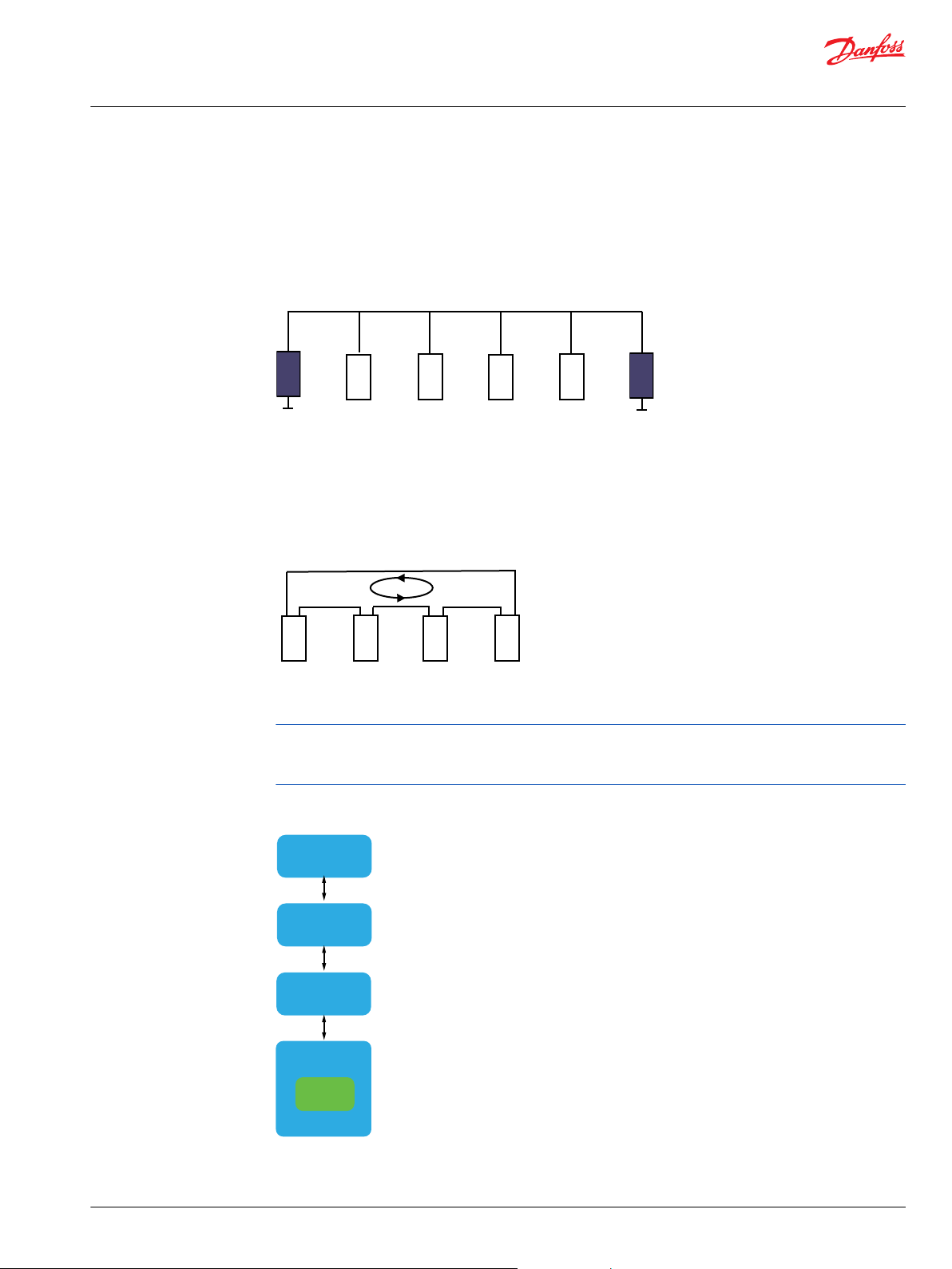
Connecting
Circuit
Driver
CAN
Controller
CPU
Software
User Manual
PLUS+1® GUIDE Extended Dynamic RedCAN User Manual
Introduction
Overview
Normal CAN structure
A normal CAN structure is illustrated below. There is one single CAN connection per module. Bus
termination is handled with external resistors.
Normal CAN Structure
Danfoss RedCAN is based on a redundant CAN communication principal. RedCAN uses two CAN
connections per module. The modules are connected in a ring structure to provide a second path for
communication in the event of a segment error.
RedCAN structure
RedCAN Structure
Termination of the bus is handled automatically inside the ECU by the RedCAN connection. No external
resistors are required.
System behavior depends on parameter settings. Incorrect parameters may lead to system malfunction. It
is recommended to disconnect the controller from the system and set parameters before reconnecting it
to the system.
RedCAN uses one standard CAN driver with controller but has the additional connecting circuit logics to
terminate the bus and provide the second communication path in the event of a bus failure.
©
Danfoss | December 2019 AQ00000114en-000201 | 5
CAN Driver
with Controller
R1 R2
RE1
RE2
CAN Driver
with Controller
R1 R2
RE1
RE2
User Manual
PLUS+1® GUIDE Extended Dynamic RedCAN User Manual
Introduction
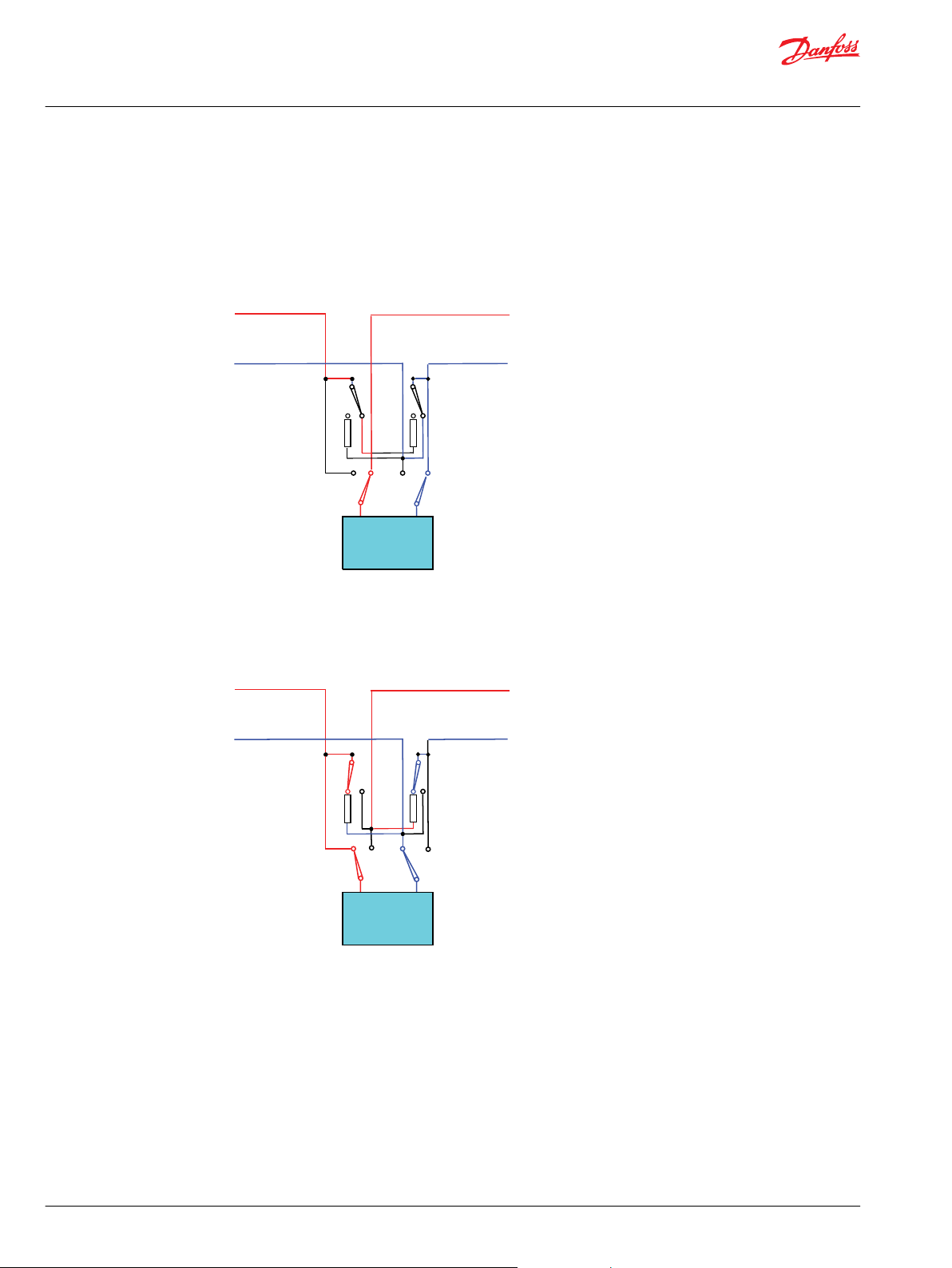
Transparent connection mode
The Connecting Circuit consists of relays that provide three different connection options:
Transparent Mode Normal and Redundant connections are both connected to the CAN controller.
Terminators are not connected.
Transparent connection mode
Normal connection mode
Normal Connection
Mode
Both Normal and Redundant connections are terminated. Only Normal
connection is connected to the CAN controller.
6 | © Danfoss | December 2019 AQ00000114en-000201
CAN Driver
with Controller
R1 R2
RE1
RE2
User Manual
PLUS+1® GUIDE Extended Dynamic RedCAN User Manual
Introduction
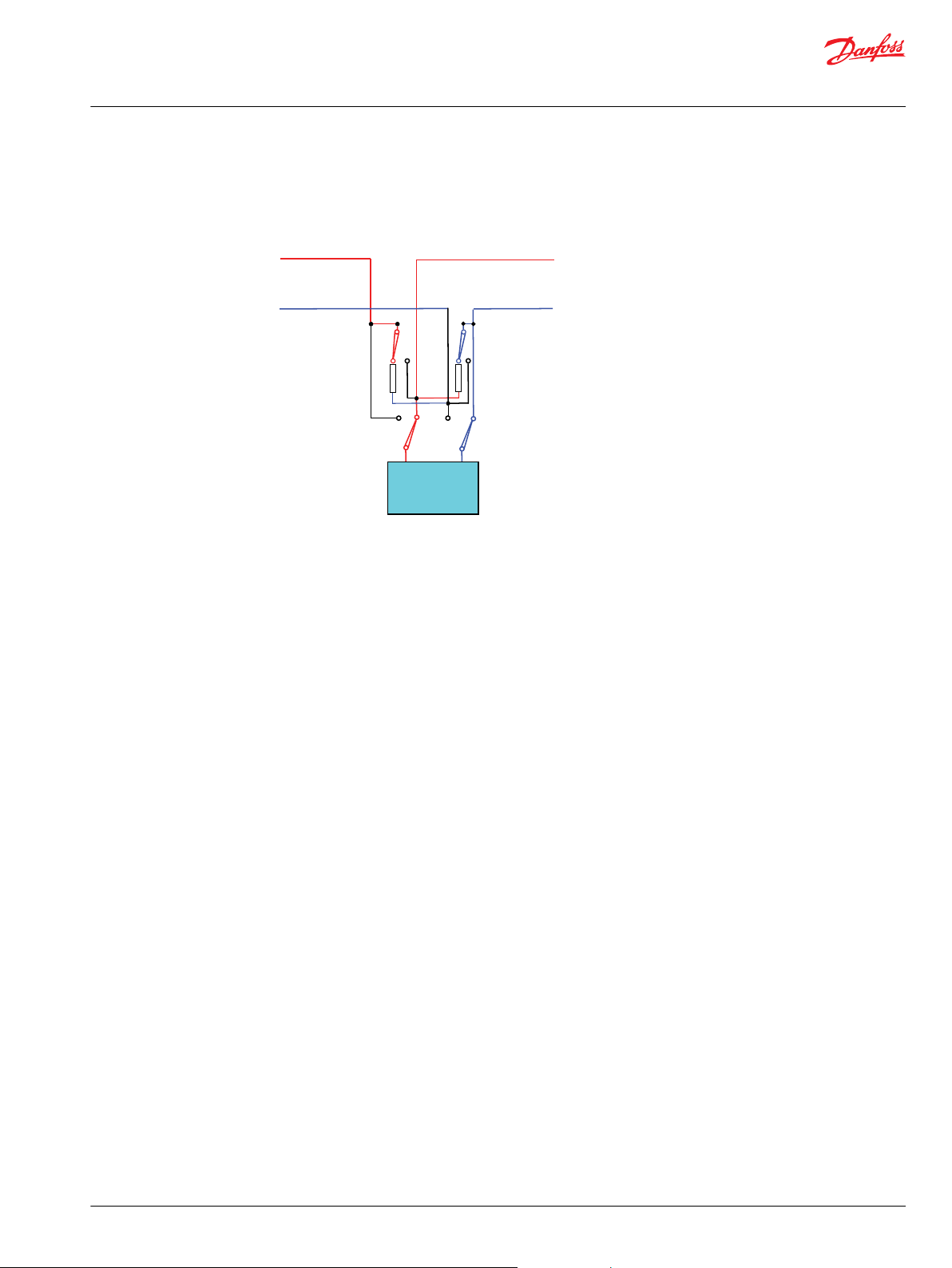
Redundant connection mode
Redundant Connection
Mode
Both Normal and Redundant connections are terminated. Only Redundant
connection is connected to the CAN controller.
©
Danfoss | December 2019 AQ00000114en-000201 | 7

User Manual
PLUS+1® GUIDE Extended Dynamic RedCAN User Manual
RedCAN Overview
Overview
Description
When using Dynamic RedCAN each node has knowledge about its closest neighbors and with that
information determines if it should act as a master holding the termination and initiating the fault
detection heartbeat or go transparent while waiting for the heartbeat to initiate.
RedCAN inputs
RedCAN function block inuputs
Input Type Range Description
Freeze BOOL — Used to turn off RedCAN
Check Appendix BOOL — Used to turn master relays to look opposite
Def System ARRAY (128) U8 — Array containing predefined system. (Lowest ID
Scan BOOL — Initialize a system scan
Max Exectime U8 5–255 Maximum execution time during system scan.
Max Timeout U16 75–50000
TimeBase U16 15–10000
CAN Bus — —
Extended_ID BOOL —
CAN_ID_Offset U32 0x0-0x1FFFFF00
Node U8 0–127
Port Port — CAN port to use
BusOff BOOL — Error on CAN wire
Reset BOOL —
direction.
in position 0, Normal neighbor in position 1,
etc).
This is the execution time of the slowest unit on
the RedCAN loop and, is used for all units
connected to the RedCAN loop. Constant
recommended (default 30 ms).
Sets how long to wait for heartbeat message
before regarded as error. Minimum default
setting is 5 times greater than Time Base (450
ms).
Sets detection timeout and heartbeat rate. (how
often the heartbeat should be sent). Minimum
default setting is 3 times greater than
Max_ExecTime (90 ms).
Use extended CAN message IDs
Offset for CAN ID to put messages in a desirable
range. Messages used are in this range (0x00–
0xFF) + Offset.
Number to distinguish nodes from each other
Output activated -> Reset BusOff (delete
connection in Unit_Config).
RedCAN Outputs
Ouput Type Range Description
OS_Out
RedCAN_RelayMode U8 0–2
Status Bus
0: Transparent
1: Normal
2: Redundant
This signal is either the signal from the RedCAN_
Link block or the signal decided from the
diagnostic tool.
8 | © Danfoss | December 2019 AQ00000114en-000201

User Manual
PLUS+1® GUIDE Extended Dynamic RedCAN User Manual
RedCAN Overview
Ouput Type Range Description
Mode S16 -1–4
NbrOfNodes U8 0–128
MisplacedArray ARRAY (128) U8 —
NodeMisplaced BOOL —
NodeNvrFnd BOOL —
NodeNvrFndArray ARRAY (128) U8 —
Fault Bus
BusError BOOL —
Node1 U8 0 – 127
Node2 U8 0 – 127
NodeGone BOOL —
NodeGoneArray ARRAY (128) U8 —
-1: Undefined (no mode has been detected after
Startup or Check Appendix)
0: System Ready
1: System Scan
2: Freeze
3: Download
4: Check Appendix
Total number of connected RedCAN nodes in the
system.
Holds information about nodes that are not
placed as defined system describes.
Flag that informs that there are nodes in the
designed system that are not connected.
Flag that informs that there are nodes in the
designed system that are not connected.
Holds information about nodes that are not
connected.
A wire error has been detected.
The error is on Normal side of this node (only
certain if all N-R connections).
The error is on the Redundant side of this node
(only certain if all N-R connections).
Flag that informs that a node has disappeared
from the system after startup.
Holds information about nodes that have been
lost since startup.
©
Danfoss | December 2019 AQ00000114en-000201 | 9

User Manual
PLUS+1® GUIDE Extended Dynamic RedCAN User Manual
Block Functions
Block types
The Extended implementation consists of five separate block parts:
•
Link Block
•
Beat Block
•
Diagnostic Block
•
Freeze Block
•
Relays Block
The blocks could all be used in every controller but it could also be that one controller acts as the
diagnostic interface and is the only one using the Diagnostic block. Other controllers in the system only
need Link and/or Beat blocks.
Link block
The Link Block detects the nodes in the System and their relative positions. It also takes care of bus
termination and disconnects faulty segments to keep the bus intact.
Link block inputs
Input Type Range Description
Freeze BOOL — Use to turn off RedCAN
Check Appendix BOOL —
System ARRAY (128) U8 —
Scan BOOL — Initialize a system scan
Init BOOL —
Delay U16 0–65535
Max Exectime U8 5–255
CAN Bus — —
Extended_ID BOOL —
CAN_ID_Offset U32
Node U8 0–127
Port — — CAN port to use
BusOff BOOL — Error on CAN wire
Reset BOOL —
0x00x1FFFFF00
Use to turn master relays to look opposite
direction. Enables detection of some faults that
may otherwise be missed.
Array containing actual system (Lowest ID in
position 0, Normal neighbor in Position 1, etc).
Controls whether a scan should be initiated on
power up.
T: Scan is initiated on power up.
F: No scan, system is regarded as correct.
Sets the delay time before heartbeat is enabled.
This is to handle differences in startup time for
the nodes in the system. Only valid when
init=false.
Maximum execution time during system scan.
Constant recommended (default 30 ms).
Use extended CAN message IDs.
Offset for CAN ID to put messages in a desirable
range. Messages used in the range (0x00–0xFF)
+ offset.
Number to distinguish nodes from each other.
Output activated-> Reset BusOff (delete
connection in Unit_Config.
10 | © Danfoss | December 2019 AQ00000114en-000201

User Manual
PLUS+1® GUIDE Extended Dynamic RedCAN User Manual
Block Functions
Link block outputs
Output Type Range Description
OS_out Bus — —
RedCAN_RelayMode U8 0–2
Status Bus — —
Mode S16 -1–4
NodeError BOOL —
Ready BOOL — System scan completed
Neighbors Bus — —
ClosestNeighb U8 0–127
IStartSprint BOOL —
ImMaster BOOL —
ImMstrOpsitNeigh BOOL —
LowestRandID U32 0–4294967295
Max_ExecTime U8 0–255 Maximum Max_ExecTime value in the system.
MyRandomID U32 0–4294967295 Needed to handle multiples with same node
NormNeighbNodeID U8 0–127
NormNeighbRandID U32 0–4294967295
OpRandID U32 0–4294967295
OppstNeighb U8 0–127
RedNeighbNodeID U8 0–127
RedNeighbRandID U32 0–4294967295 Needed to handle multiples with same node
0: Transparent
1: Normal
2:Redundant
-1: Undefined (no mode has been detected after
Startup or Check Appendix)
0: System Ready
1:System Scan
2: Freeze
3: Download
4: Check Appendix
Error found during system scan
Node ID of the neighbor the side that relays are
turned towards.
The lowest node in the system that initiates the
heart beat. First position in system array.
The lowest terminating node. Master.
The node on the opposite side of the master.
Needed to handle multiples with same node
number.
Used to set the limits for beat block timings.
number.
Node ID of the normal side neighbor.
Needed to handle multiples with same node
number.
Needed to handle multiples with same node
number.
Node ID of the opposite side neighbor.
Node ID of the Redundant side neighbor.
number.
Beat block
The Beat Block detects the absolute position of the nodes (actual system) and detects errors in runtime
Beat block inputs
Input Type Range Description
Enable BOOL — Enable heartbeat function. Connected to Link
Neighbors Bus — Information about the system to determine how
©
Danfoss | December 2019 AQ00000114en-000201 | 11
block output ready by default.
the heartbeat should be sent through the
system.

User Manual
PLUS+1® GUIDE Extended Dynamic RedCAN User Manual
Block Functions
Input Type Range Description
IStartSprint BOOL — The lowest node in the system that initiates the
ImMaster BOOL — The lowest terminating node. Master.
ImMstrOpsitNeigh BOOL — The node on the opposite side of the master.
LowestRandID U32 0–4294967295 Needed to handle multiples with the same node
Max_ExecTime U8 0–255 Maximum Max_ExecTime
MyRandomID U32 0–4294967295 Needed to handle multiples with the same node
NormNeighbNodeID U8 0–127 Node ID of the Normal side neighbor.
NormNeighbRandID U32 0–4294967295 Needed to handle multiples with the same node
OpRandID U32 0–4294967295 Needed to handle multiples with the same node
OppstNeighb U8 0–127 Node ID of the opposite side neighbor.
RedNeighbNodeID U8 0–127 Node ID of the redundant side neighbor.
RedNeighbRandID U32 0–4294967295 Needed to handle multiples with same node
Max Timeout U16 75–50000
TimeBase U16 15–10000
CAN Bus — —
Extended_ID BOOL — Use extended CAN message IDs.
CAN_ID_Offset U32
Node U8 0–127 Numbers to distinguish nodes from each other.
Port — — CAN port to use
0x00x1FFFFF00
heartbeat. First position in system array.
number.
number.
number.
number.
number.
Sets how long to wait for heartbeat message
before regarded aserror. Minimum default
setting is 5 times greater than Time Base (450
ms).
Sets detection timeout and heartbeat rate. (how
often the heartbeat should be sent).
Minimum default setting is 3 times greater than
Max_ExecTime (90 ms).
Offset for CAN ID to put messages in a desirable
range (0x00–0xFF) + Offset.
Beat block outputs
Output Type Range Description
Status Bus — —
FirstDone BOOL — First heartbeat loop done.
MasterMsg ARRAY (128) U8 —
NbrOfNodes U8 0–128
System_OK BOOL — No errors detected.
System ARRAY (128) U8 —
Scan BOOL — Initiate a system scan.
Holds information about terminating nodes.
Used to report wire errors.
Total number of connected RedCAN nodes in
system
Array containing actual system (Lowest ID in
position 0, Normal neighbor in Position 1, etc).
12 | © Danfoss | December 2019 AQ00000114en-000201

User Manual
PLUS+1® GUIDE Extended Dynamic RedCAN User Manual
Block Functions
Diagnostic block
The Diagnostic block recieves information from the other two blocks to report different types of error
situations.
Diagnostic block inputs
Input Type Range Description
Link Status Bus —
Mode S16 -1 –4
NodeError BOOL —
BeatStatus Bus — —
FirstDone BOOL — First heartbeat loop done
MasterMsg ARRAY (8) U8 —
NbrOfNodes U8 0–128
NodeFault BOOL —
Def System ARRAY (128) U8 —
Act System ARRAY (128) U8 —
CAN Bus — —
Extended_ID BOOL —
CAN_ID_Offset U32
Port — — CAN port to use
0x00x1FFFFF00
-1: Undefined (no mode has been detected after
Startup or Check Appendix)
0: System Ready
1: System Scan
2: Freeze
3: Download
4: Check Appendix
An error has been detected during system scan.
Holds information about terminating nodes.
Total number of connected RedCAN nodes in
system.
A node has failed to pass on the heart beat.
Predefined system, what the desired system
looks like.
Actual system, how the system looks (Lowest ID
in position 0, Normal neighbor in position 1,
etc).
Use Extended CAN message IDs
Offset for CAN ID to put messages in a desirable
range. (0x00–0xFF) + Offset
Diagnistic block outputs
Output Type Range Description
Status Bus — —
Mode S16 -1–4
NbrOfNodes U8 0–128
MisplacedArray ARRAY (128) U8 —
NodeMissplaced BOOL —
NodeNvrFnd BOOL —
©
Danfoss | December 2019 AQ00000114en-000201 | 13
-1: Undefined (no mode has been detected after
Startup or Check Appendix)
0: System Ready
1: System Scan
2: Freeze
3: Download
4: Check Appendix
Total number of connected RedCAN nodes in
system.
Holds information about nodes that are not
placed as defined system implies.
Flag that informs that there are nodes with
wrong position in system.
Flag that informs that there are nodes in the
designed system that are not connected.

User Manual
PLUS+1® GUIDE Extended Dynamic RedCAN User Manual
Block Functions
Output Type Range Description
NodeNvrFndArray ARRAY (128) U8 —
Fault Bus — —
BusError BOOL —
Node1 U8 0–127
Node2 U8 0–127
NodeGone BOOL —
NodeGoneAway ARRAY (128) U8 —
Freeze block
The Freeze block listens to CAN message KP0 from the Service Tool to set RedCAN to freeze. Therefore it
will keep its current status and will not react to any faults.
Holds information about nodes that are not
connected.
A wire error has been detected.
There is an error between Node 1 and Node 2.
The error is on the Normal side of this node.
(Only certain if all N–R connections).
There is an error between Node 1 and Node 2.
The error is on the Redundant side of this node.
(only certain if all N–R connections)
Flag that informs that a node has disappeared
from the system after startup.
Holds information about nodes that have been
lost since startup.
Freeze block inputs
Freeze block outputs
Relays block
Relays block inputs
Input Type Range Description
CAN Bus — —
Node U8 0–127
Port — — CAN port to use
Output Type Range Description
Freeze BOOL —
Checkpoint — — —
CP_RedCANFreeze
Number to distinguish nodes from each other
Freeze set from diagnostic tool
Shows current freeze status
The Relays block controls the steering of the RedCAN relays. When the RedCAN block is in freeze, it is
possible to set the relays to either Transparent, Normal or Redundant. The Relays block listens to CAN
message KP136.
Input Type Range Description
Freeze BOOL —
CAN Bus — —
Node U8 0–127
Port — — CAN port to use
Freeze set from diagnostic tool
Number to distinguish nodes from one another
14 | © Danfoss | December 2019 AQ00000114en-000201

User Manual
PLUS+1® GUIDE Extended Dynamic RedCAN User Manual
Block Functions
Input Type Range Description
OS_In Bus — —
RedCAN_RelayMode U8 0–2
Relays block outputs
Output Type Range Description
OS_Out — — —
RedCAN_RelayMode U8 0–2
Checkpoint — — —
CP_RedCANRelayMod U8 0–2
0: Transparent
1: Normal
2: Redundant
The signal coming from the RedCAN_Link block.
This is the signal determined from the last
linking of the units.
0: Transparent
1: Normal
2: Redundant
This signal is either the signal from the
RedCANLink block or the signal decided from
the service tool.
Shows the current status of the RedCAN relay
mode.
©
Danfoss | December 2019 AQ00000114en-000201 | 15

2
2
3
2
2
3
2
2
2
1
1
3
User Manual
PLUS+1® GUIDE Extended Dynamic RedCAN User Manual
Theory of Operations
Theory of operation
When the system is complete and there are no faults, each node could be in any of the following states:
Scanning. No Neighbor found
Normal neighbor found. Perform
handshake.
Redundant neighbor found. Perform
handshake
Own node ID: 2, Lowest node ID: 2.
None found: Lowest = Own
Own node ID: 2, Lowest node ID: 2,
Normal neighbor: 3
Own node ID: 3, Lowest node ID: 2,
Redundant neighbor: 2
Lower node ID detected. Set
Transparent
16 | © Danfoss | December 2019 AQ00000114en-000201
Own node ID: 2, Lowest node ID: 1,
Own ID (2) >Lowest ID (1), Normal
neighbor : 3, Redundant neighbor : 1

2
1
5
5
1
5
Done
1
4 1
5
Done
1
4 1
5
4
3
2
1
1 2 3 4 5
Lowest Known ID
User Manual
PLUS+1® GUIDE Extended Dynamic RedCAN User Manual
Theory of Operations
Node is detected as lowest Node ID,
terminate and ask for opposite
neighbor
Node is asked for as opposite
neighbor. Reply
Lowest Node ID has recieved reply
from opposite neighbor. Ring is
complete and • heart beat is initiated
Own Node ID : 1, Lowest Node ID : 1,
Own ID (1) = Lowest ID, Normal
neighbor : 2, Redundant neighbor : 5,
Opposite neighbor : 5
Own Node ID :5, Lowest Node ID : 1,
Normal neighbor : 1, Redundant
neighbor : 4, Opposite neighbor : 5,
Own ID (5) : Opposite neighbor
At start up, or if an error is detected, a scan system is initialized:
©
Danfoss | December 2019 AQ00000114en-000201 | 17
5
4
3
2
1
1 2 2 4 4
3
5
Lowest Known ID
2 4
5
4
3
2
1
1 1 2 4
2 1
3
2
4
3
4
5
Lowest Known ID
3
5
4
3
2
1
1 1 2 1
2 1
3
2
4
3
45
2 >1
3 > 2
1
1
Lowest Known ID
4 > 3
3
User Manual
PLUS+1® GUIDE Extended Dynamic RedCAN User Manual
Theory of Operations
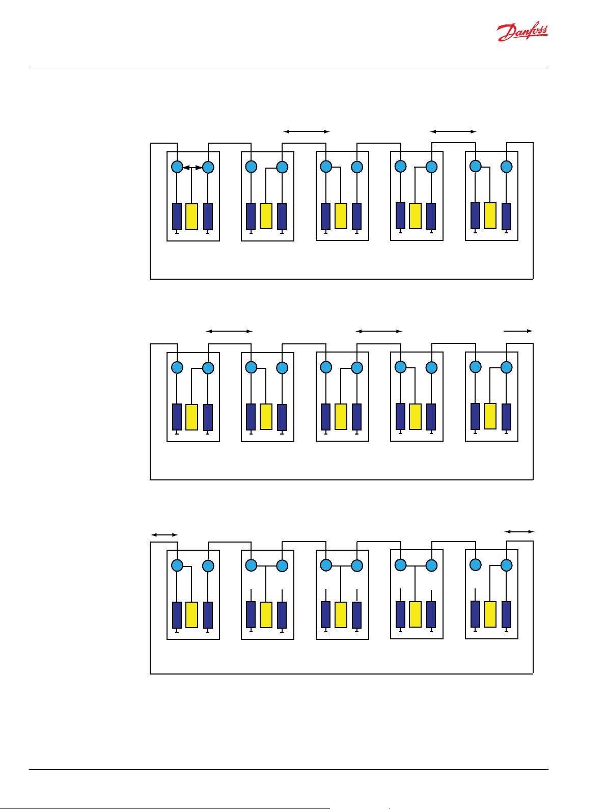
The position in the system determines if the node should turn to the normal or the redundant side:
When the neighbor has been detected or if the random time out passes, the node turns toward the opposite
side.
When the Node ID is not the lowest known ID in the system and both neighbors are found, the node turns
transparent.
18 | © Danfoss | December 2019 AQ00000114en-000201

5
4
3
2
1
1 1 2 1
2 1
3
2
4
3
45
5 > 1
1
1=1
5
5
Lowest Known ID
3
5
4
3
2
1
1 1 1 1 1
2 1
3
2
4
3
4
5
5 = 5
1
1=1
5
5
Lowest Known ID
5
4
3
2
1
1 1 1 1 1
2 1
3
2
4
3
45
1
5
2
1=1
2=2
Lowest Known ID
User Manual
PLUS+1® GUIDE Extended Dynamic RedCAN User Manual
Theory of Operations
The lowest known ID in the system takes the role of master and holds termination for the system.
The lowest known ID in the system takes the role of master and holds termination for the system.
Then turns and ask for other opposite neighbor to ensure a complete system and the opposite neighbor
applies.
©
Danfoss | December 2019 AQ00000114en-000201 | 19

5
4
3
2
1
1 1 1
2 1
3
2
4
3
45
1
Done
5
Lowest Known ID
1
1
User Manual
PLUS+1® GUIDE Extended Dynamic RedCAN User Manual
Theory of Operations
The master then sends out a system OK and initiates the heart beat.
Theory of operation: Summary
When the system is connected (Mode = 0), a heartbeat message is transmitted to confirm a healthy
communication path. Each node then listens to the heartbeat messages from its two neighbors and if
one of the messages does not come through an error is declared and a new scan is initiated.
To determine the exact setup of the system, a sequence of messages is sent from the master node to it’s
neighbor in normal direction. The messages are then passed on to the next neighbor until the complete
system is covered. In this way, all nodes will get information about the complete system setup and it can
be compared with the predefined system to detect errors in node order.
It is optional to scan at power up. If init is false, a scan is not triggered and the system input is used as a
predefined system to determine the master node (terminating and starting the heart beat). The entire
ring is always checked at startup by the master asking for opposite neighbors in both directions.
20 | © Danfoss | December 2019 AQ00000114en-000201

User Manual
PLUS+1® GUIDE Extended Dynamic RedCAN User Manual
Troubleshooting
Possible error conditions
This table identifies errors that could possibly occur:
Problem Possible Cause
Bus/segment errors CAN wires shortened, faulty ground connection
Node missing/ not responding or ‘babbling idiot’
behavior
Node misplaced Positions in actual system differ from defined system
Fixing errors
The time to detect an error and fix it depends on the parameter settings. The parameter ‘Time Base’ sets
the timeout for the heartbeat message. This is the error detection time. The parameter ‘Max_ExecTime’ is
used to calculate how long a node will wait for a response before changing direction during a scan. The
theoretical worst case scan time is 112*Max_ExecTime, calculated based on the total timeout. The
theoretical best time is 32*Max_ExecTime, based on the time for communicating only (no waiting time).
The total fix time is the sum of error detection time and scan time:
•
Worst Case fix time: TimeBase + 112*Max_ExecTime
•
Best Case fix time: Time Base + 32*Max_ExecTime
All nodes in defined system are not present in actual
system
Table of errors and system reactions
If several errors appear at once, they are all reported but a functional system cannot be guaranteed if
more than one error occurs at the same time.
RedCAN is able to handle the first error and report where the first error occurs so it can be fixed. But, if
that error is not fixed then there is no guarantee that the system will continue to work if another error is
occurring.
Output Type Range Description
Status Bus — —
Mode S16 -1–4
NbrOfNodes U8 0–128
MisplacedArray ARRAY (128) U8 —
NodeMissplaced BOOL —
NodeNvrFnd BOOL —
NodeNvrFndArray ARRAY (128) U8 —
Fault Bus — —
BusError BOOL —
Node1 U8 0–127
-1: Undefined (no mode has been detected)
0: System Ready
1: System Scan
2: Freeze
3: Download
4: Check Appendix
Total number of connected RedCAN nodes in
system
Holds information about nodes that are not placed
as defined system implies.
Flag that informs that there are nodes with wrong
position in system.
Flag that informs that there are nodes in the
designed system that are not connected.
Holds information about nodes that are not
connected.
A wire error has been detected.
There is an error between Node 1 and Node 2.
The error is on the Normal side of this node. (Only
certain if all N–R connections).
©
Danfoss | December 2019 AQ00000114en-000201 | 21

User Manual
PLUS+1® GUIDE Extended Dynamic RedCAN User Manual
Troubleshooting
Output Type Range Description
Node2 U8 0–127
NodeGone BOOL —
NodeGoneAway ARRAY (128) U8 —
There is an error between Node 1 and Node 2. The
error is on the Redundant side of this node (only
certain if all N–R connections).
Flag that informs that a node has disappeared from
the system after startup.
Holds information about nodes that have been lost
since startup.
22 | © Danfoss | December 2019 AQ00000114en-000201

Danfoss
Power Solutions GmbH & Co. OHG
Krokamp 35
D-24539 Neumünster, Germany
Phone: +49 4321 871 0
Danfoss
Power Solutions ApS
Nordborgvej 81
DK-6430 Nordborg, Denmark
Phone: +45 7488 2222
Danfoss
Power Solutions (US) Company
2800 East 13th Street
Ames, IA 50010, USA
Phone: +1 515 239 6000
Danfoss
Power Solutions Trading
(Shanghai) Co., Ltd.
Building #22, No. 1000 Jin Hai Rd
Jin Qiao, Pudong New District
Shanghai, China 201206
Phone: +86 21 2080 6201
Products we offer:
Hydro-Gear
www.hydro-gear.com
Daikin-Sauer-Danfoss
www.daikin-sauer-danfoss.com
DCV directional control
•
valves
Electric converters
•
Electric machines
•
Electric motors
•
Gear motors
•
Gear pumps
•
Hydrostatic motors
•
Hydrostatic pumps
•
Orbital motors
•
PLUS+1® controllers
•
PLUS+1® displays
•
PLUS+1® joysticks and
•
pedals
PLUS+1® operator
•
interfaces
PLUS+1® sensors
•
PLUS+1® software
•
PLUS+1® software services,
•
support and training
Position controls and
•
sensors
PVG proportional valves
•
Steering components and
•
systems
Telematics
•
Danfoss Power Solutions is a global manufacturer and supplier of high-quality hydraulic and
electric components. We specialize in providing state-of-the-art technology and solutions
that excel in the harsh operating conditions of the mobile off-highway market as well as the
marine sector. Building on our extensive applications expertise, we work closely with you to
ensure exceptional performance for a broad range of applications. We help you and other
customers around the world speed up system development, reduce costs and bring vehicles
and vessels to market faster.
Danfoss Power Solutions – your strongest partner in mobile hydraulics and mobile
electrification.
Go to www.danfoss.com for further product information.
We offer you expert worldwide support for ensuring the best possible solutions for
outstanding performance. And with an extensive network of Global Service Partners, we also
provide you with comprehensive global service for all of our components.
Local address:
Danfoss can accept no responsibility for possible errors in catalogues, brochures and other printed material. Danfoss reserves the right to alter its products without notice. This also applies to products
already on order provided that such alterations can be made without subsequent changes being necessary in specifications already agreed.
All trademarks in this material are property of the respective companies. Danfoss and the Danfoss logotype are trademarks of Danfoss A/S. All rights reserved.
©
Danfoss | December 2019 AQ00000114en-000201
 Loading...