

Page 1
Technical Information
Orbital Motors
Type RE
powersolutions.danfoss.com
Page 2

2 | © Danfoss | May 2018 BC267979667405en-000101
Page 3

TABLE OF CONTENTS
TECHNICAL INFORMATION
Operating Recommendations ....................................................................................................................................... 4-5
Motor Connections .......................................................................................................................................................... 5
Product Testing (Understanding the Performance Charts) .............................................................................................. 6
Allowable Bearing & Shaft Loads .................................................................................................................................... 7
Vehicle Drive Calculations ............................................................................................................................................ 8-9
Induced Side Loading .................................................................................................................................................... 10
Hydraulic Equations....................................................................................................................................................... 10
Shaft Nut Dimensions & Torque Specications ..............................................................................................................11
OPTIONAL MOTOR FEATURES
Speed Sensor Options ............................................................................................................................................. 12-13
Freeturning Rotor Option ............................................................................................................................................... 13
Internal Drain ................................................................................................................................................................. 14
Hydraulic Declutch......................................................................................................................................................... 14
Valve Cavity Option ....................................................................................................................................................... 15
Slinger Seal Option........................................................................................................................................................ 15
MEDIUM DUTY HYDRAULIC MOTORS
RE Product Line Introduction......................................................................................................................................... 16
RE Displacement Performance Charts..................................................................................................................... 17-22
505 & 506 Series Housings ...................................................................................................................................... 23-24
505 & 506 Series Technical Information ........................................................................................................................ 25
505 & 506 Series Shafts ................................................................................................................................................ 26
505 & 506 Series Ordering Information ......................................................................................................................... 27
520 & 521 Series Housings ........................................................................................................................................... 28
520 & 521 Series Technical Information ........................................................................................................................ 29
520 & 521 Series Shafts ................................................................................................................................................ 30
520 & 521 Series Ordering Information ......................................................................................................................... 31
530 & 531 Series Housings ........................................................................................................................................... 32
530 & 531 Series Technical Information ........................................................................................................................ 33
530 & 531 Series Shafts ................................................................................................................................................ 34
530 & 531 Series Ordering Information ......................................................................................................................... 35
535 & 536 Series Housings ........................................................................................................................................... 36
535 & 536 Series Technical Information ........................................................................................................................ 36
535 & 536 Series Shafts ................................................................................................................................................ 37
535 & 536 Series Ordering Information ......................................................................................................................... 37
540 & 541 Series Housings ........................................................................................................................................... 38
540 & 541 Series Technical Information ........................................................................................................................ 39
540 & 541 Series Ordering Information ......................................................................................................................... 39
BC267979667405en-000101 | 3© Danfoss | May 2018
Page 4

OPERATING RECOMMENDATIONS
OIL TYPE
Hydraulic oils with anti-wear, anti-foam and demulsiers
are recommended for systems incorporating Danfoss motors. Straight oils can be used but may require VI (viscosity
index) improvers depending on the operating temperature
range of the system. Other water based and environmentally friendly oils may be used, but service life of the motor
and other components in the system may be signicantly
shortened. Before using any type of uid, consult the uid
requirements for all components in the system for compatibility. Testing under actual operating conditions is the only
way to determine if acceptable service life will be achieved.
FLUID VISCOSITY & FILTRATION
Fluids with a viscosity between 20 - 43 cSt [100 - 200
S.U.S.] at operating temperature is recommended. Fluid
temperature should also be maintained below 85°C [180°
F]. It is also suggested that the type of pump and its oper-
ating specications be taken into account when choosing
a uid for the system. Fluids with high viscosity can cause
cavitation at the inlet side of the pump. Systems that operate
over a wide range of temperatures may require viscosity
improvers to provide acceptable uid performance.
congured for this condition, damage to the motor or system
can occur. To protect against this condition a counterbalance valve or relief cartridge must be incorporated into the
circuit to reduce the risk of overpressurization. If a relief
cartridge is used, it must be installed upline of the motor,
if not in the motor, to relieve the pressure created by the
over-running motor. To provide proper motor protection for
an over-running load application, the pressure setting of
the pressure relief valve must not exceed the intermittent
rating of the motor.
HYDRAULIC MOTOR SAFETY PRECAUTION
A hydraulic motor must not be used to hold a suspended
load. Due to the necessary internal tolerances, all hydraulic
motors will experience some degree of creep when a load
induced torque is applied to a motor at rest. All applications that require a load to be held must use some form of
mechanical brake designed for that purpose.
MOTOR/BRAKE PRECAUTION
Caution! - Danfoss motor/brakes are intended to operate as
static or parking brakes. System circuitry must be designed
to bring the load to a stop before applying the brake.
Danfoss recommends maintaining an oil cleanliness level
of ISO 17-14 or better.
INSTALLATION & START-UP
When installing a Danfoss motor it is important that the
mounting ange of the motor makes full contact with the
mounting surface of the application. Mounting hardware of
the appropriate grade and size must be used. Hubs, pul-
leys, sprockets and couplings must be properly aligned to
avoid inducing excessive thrust or radial loads. Although
the output device must t the shaft snug, a hammer should
never be used to install any type of output device onto the
shaft. The port plugs should only be removed from the motor when the system connections are ready to be made. To
avoid contamination, remove all matter from around the
ports of the motor and the threads of the ttings. Once all
system connections are made, it is recommended that the
motor be run-in for 15-30 minutes at no load and half speed
to remove air from the hydraulic system.
MOTOR PROTECTION
Over-pressurization of a motor is one of the primary causes
of motor failure. To prevent these situations, it is necessary
to provide adequate relief protection for a motor based on
the pressure ratings for that particular model. For systems
that may experience overrunning conditions, special pre-
cautions must be taken. In an overrunning condition, the
motor functions as a pump and attempts to convert kinetic
energy into hydraulic energy. Unless the system is properly
Caution! - Because it is possible for some large displace-
ment motors to overpower the brake, it is critical that the
maximum system pressure be limited for these applications.
Failure to do so could cause serious injury or death. When
choosing a motor/brake for an application, consult the
performance chart for the series and displacement chosen
for the application to verify that the maximum operating
pressure of the system will not allow the motor to produce
more torque than the maximum rating of the brake. Also,
it is vital that the system relief be set low enough to insure
that the motor is not able to overpower the brake.
To ensure proper operation of the brake, a separate case
drain back to tank must be used. Use of the internal drain
option is not recommended due to the possibility of return
line pressure spikes. A simple schematic of a system utilizing a motor/brake is shown on page 4. Although maximum
brake release pressure may be used for an application, a
34 bar [500 psi] pressure reducing valve is recommended
to promote maximum life for the brake release piston seals.
However, if a pressure reducing valve is used in a system
which has case drain back pressure, the pressure reducing
valve should be set to 34 bar [500 psi] over the expected
case pressure to ensure full brake release. To achieve
proper brake release operation, it is necessary to bleed
out any trapped air and ll brake release cavity and hoses
before all connections are tightened. To facilitate this op-
eration, all motor/brakes feature two release ports. One or
both of these ports may be used to release the brake in the
4 | © Danfoss | May 2018 BC267979667405en-000101
Page 5
OPERATING RECOMMENDATIONS & MOTOR CONNECTIONS
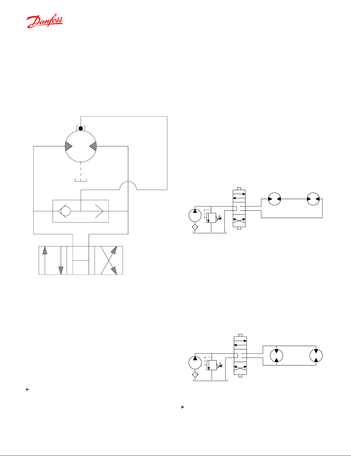
SERIES CIRCUIT
SERIES CIRCUIT
TYPICAL MOTOR/BRAKE SCHEMATIC
MOTOR/BRAKE PRECAUTION (continued)
unit. Motor/brakes should be congured so that the release
ports are near the top of the unit in the installed position.
MOTOR CIRCUITS
There are two common types of circuits used for connecting multiple numbers of motors – series connection and
parallel connection.
SERIES CONNECTION
When motors are connected in series, the outlet of one motor is connected to the inlet of the next motor. This allows
the full pump ow to go through each motor and provide
maximum speed. Pressure and torque are distributed between the motors based on the load each motor is subjected
to. The maximum system pressure must be no greater than
the maximum inlet pressure of the rst motor. The allowable
back pressure rating for a motor must also be considered. In
some series circuits the motors must have an external case
drain connected. A series connection is desirable when it
is important for all the motors to run the same speed such
as on a long line conveyor.
Once all system connections are made, one release port
must be opened to atmosphere and the brake release line
carefully charged with uid until all air is removed from the
line and motor/brake release cavity. When this has been
accomplished the port plug or secondary release line must
be reinstalled. In the event of a pump or battery failure, an
external pressure source may be connected to the brake
release port to release the brake, allowing the machine to
be moved.
NOTE: It is vital that all operating recommendations be followed. Failure to do so
could result in injury or death.
PARALLEL CONNECTION
In a parallel connection all of the motor inlets are connected.
This makes the maximum system pressure available to
each motor allowing each motor to produce full torque at
that pressure. The pump ow is split between the individual
motors according to their loads and displacements. If one
motor has no load, the oil will take the path of least resistance and all the ow will go to that one motor. The others
will not turn. If this condition can occur, a ow divider is
recommended to distribute the oil and act as a differential.
NOTE: The motor circuits shown above are for illustration purposes only.
Components and circuitry for actual applications may vary greatly and should be
chosen based on the application.
BC267979667405en-000101 | 5© Danfoss | May 2018
Page 6
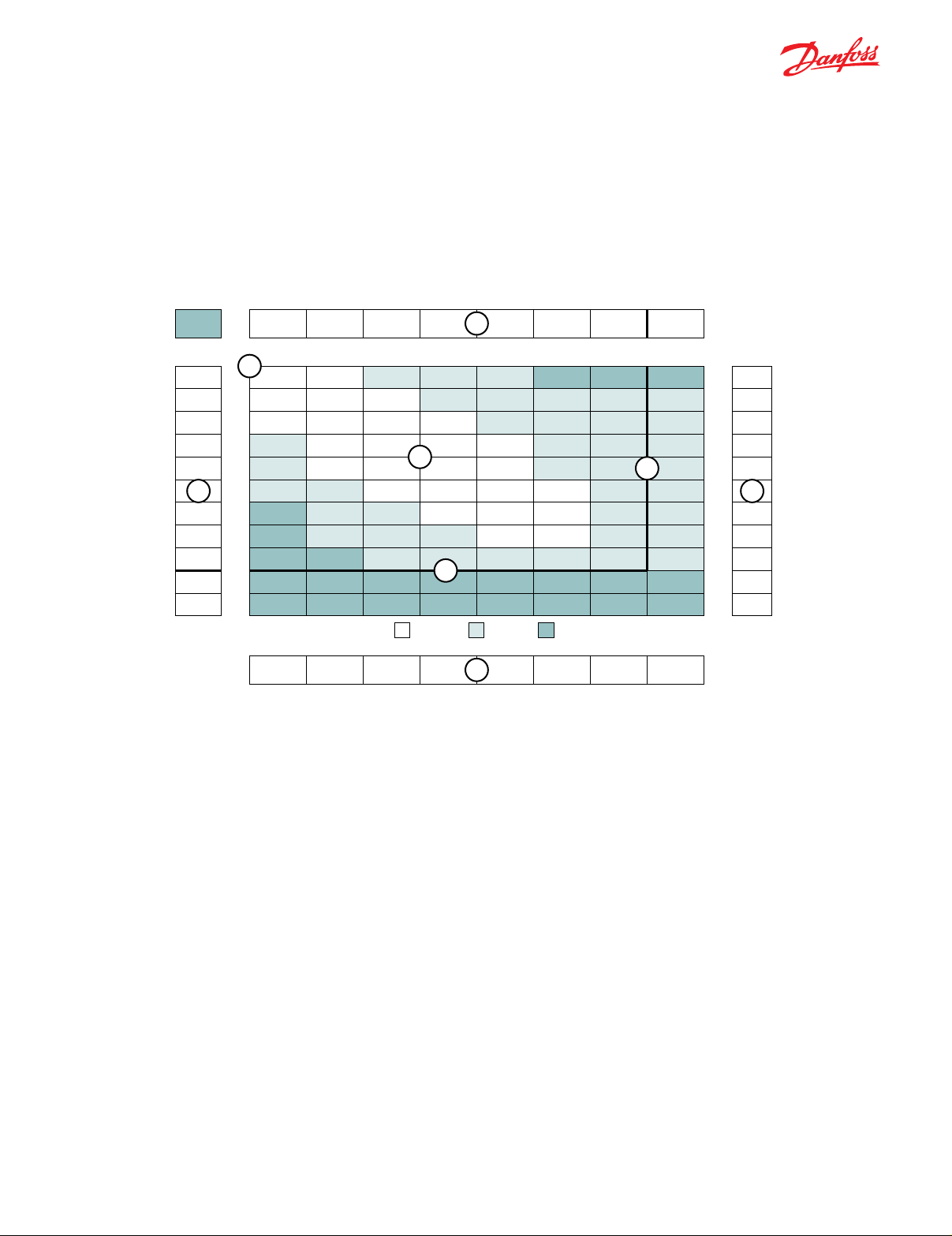
PRODUCT TESTING
Max.
Max.
Theoretical rpm
Displacement tested at 54°C [129°F] with an oil viscosity of 46cSt [213 SUS]
Performance testing is the critical measure of a motor’s ability to convert ow and pressure into speed and torque. All
product testing is conducted using Danfoss state of the art test facility. This facility utilizes fully automated test equipment and custom designed software to provide accurate, reliable test data. Test routines are standardized, including
test stand calibration and stabilization of uid temperature and viscosity, to provide consistent data. The example below
provides an explanation of the values pertaining to each heading on the performance chart.
080
76 cc [4.6 in3/rev.]
2 [0.5]
4 [1]
8 [2]
Flow - lpm [gpm]
15 [4]
23 [6]
30 [8]
1
38 [10]
45 [12]
53 [14]
Cont.
61 [16]
64 [17]
Inter.
Pressure - bars [psi]
17 [250] 35 [500] 69 [1000] 104 [1500] 138 [2000] 173 [2500] 207 [3000] 242 [3500]
Torque - Nm [lb-in], Speed rpm
6
[127]
14
25
[140]
16
50
[139]
16
100
[127]
14
200
[113]
13
301
[91]
10
401
Overall Efficiency -
Theoretical Torque - Nm [lb-in]
21 [183] 41 [366] 83 [732] 124 [1099] 166 [1465] 207 [1831] 248 [2197] 290 [2564]
30
32
32
31
30
27
24
20
14
24
50
100
200
300
400
502
602
690
[262]
[286]
[280]
[275]
[262]
[243]
[212]
[177]
[127]
61
63
64
65
63
61
58
54
50
70 - 100%
21
43
99
199
297
398
500
601
689
[543]
[559]
[563]
[572]
[557]
[536]
[511]
[482]
[445]
7
[806]
91
18
[839]
95
43
[857]
97
92
[872]
99
191
[853]
96
295
[826]
93
390
[790]
89
499
[767]
87
600
[741]
84
688
5
40 - 69%
2
Intermittent Ratings - 10% of Operation
[1062]
120
124
129
131
130
127
123
120
124
17
[1099]
34
[1139]
87
[1155]
181
[1149]
284
[1125]
384
[1087]
498
[1060]
597
[1098]
658
0 - 39%
145
151
157
160
160
159
156
164
155
[1285]
11
[1340]
32
[1390]
79
[1420]
174
[1420]
271
[1409]
372
[1379]
485
[1451]
540
[1369]
644
169
178
187
186
186
187
185
193
185
8
[1496]
11
[1579]
32
[1652]
78
[1643]
160
[1646]
253
[1654]
346
[1638]
443
[1711]
526
[1640]
631
Max. Inter.Max. Cont.
191
203
211
216
218
3
220
213
228
217
[1693]
9
[1796]
31
[1865]
77
[1911]
154
[1930]
245
[1945]
339
[1883]
433
[2021]
510
[1918]
613
26
51
101
201
302
402
4
503
603
704
804
904
Flow represents the amount of uid passing through
1.
the motor during each minute of the test.
Performance numbers represent the actual torque
6.
and speed generated by the motor based on the cor-
responding input pressure and ow. The numbers on
Pressure refers to the measured pressure differential
2.
between the inlet and return ports of the motor during
the test.
The maximum continuous pressure rating and maxi-
3.
mum intermittent pressure rating of the motor are
the top row indicate torque as measured in Nm [lb-in],
while the bottom number represents the speed of the
output shaft.
Areas within the white shading represent maximum
7.
motor efciencies.
separated by the dark lines on the chart.
Theoretical Torque represents the torque that the motor
8.
Theoretical RPM represents the RPM that the motor
4.
would produce if it were 100% volumetrically efcient.
Measured RPM divided by the theoretical RPM give the
would produce if it were 100% mechanically efcient.
Actual torque divided by the theoretical torque gives the
actual mechanical efciency of the motor.
actual volumetric efciency of the motor.
The maximum continuous ow rating and maximum
5.
intermittent ow rating of the motor are separated by
the dark line on the chart.
6 | © Danfoss | May 2018 BC267979667405en-000101
Page 7
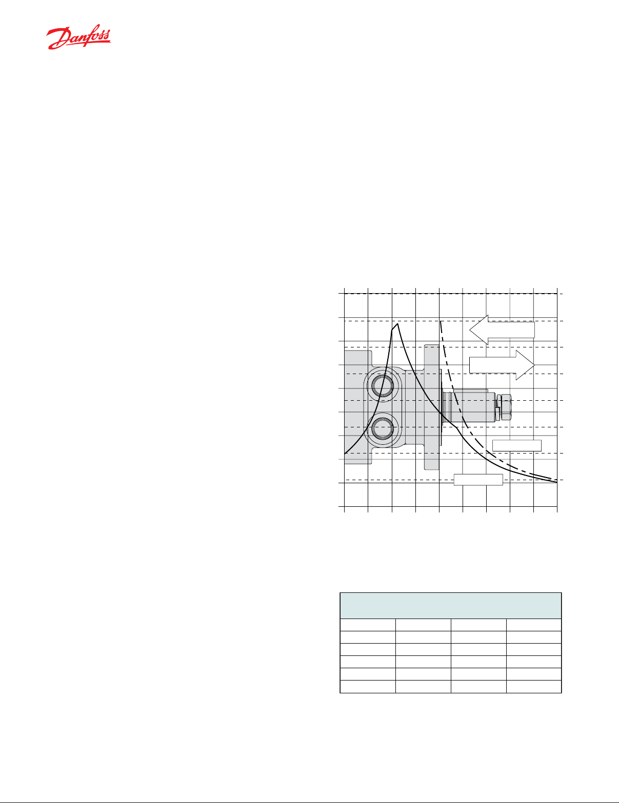
ALLOWABLE BEARING & SHAFT LOADING
-100 -50 -25 0255075 100 mm-75
-100 -50 -25 0255075 100 mm-75
This catalog provides curves showing allowable radial loads at points along the longitudinal axis of the motor. They are
dimensioned from the mounting ange. Two capacity curves for the shaft and bearings are shown. A vertical line through
the centerline of the load drawn to intersect the x-axis intersects the curves at the load capacity of the shaft and of the
bearing.
In the example below the maximum radial load bearing rating is between the internal roller bearings illustrated with a
solid line. The allowable shaft rating is shown with a dotted line.
The bearing curves for each model are based on labratory analysis and testing results constructed at Danfoss. The shaft
loading is based on a 3:1 safety factor and 330 Kpsi tensile strength. The allowable load is the lower of the curves at a
given point. For instance, one inch in front of the mounting ange the bearing capacity is lower than the shaft capacity.
In this case, the bearing is the limiting load. The motor user needs to determine which series of motor to use based on
their application knowledge.
ISO 281 RATINGS VS. MANUFACTURERS RATINGS
Published bearing curves can come from more than one
type of analysis. The ISO 281 bearing rating is an interna-
9000
4000
tional standard for the dynamic load rating of roller bearings.
The rating is for a set load at a speed of 33 1/3 RPM for
500 hours (1 million revolutions). The standard was established to allow consistent comparisons of similar bearings
between manufacturers. The ISO 281 bearing ratings are
based solely on the physical characteristics of the bear-
ings, removing any manufacturers specic safety factors
or empirical data that inuences the ratings.
Manufacturers’ ratings are adjusted by diverse and system-
atic laboratory investigations, checked constantly with feedback from practical experience. Factors taken into account
that affect bearing life are material, lubrication, cleanliness
8000
7000
6000
5000
4000
3000
2000
445 daN [1000 lb]
445 daN [1000 lb]
SHAFT
3500
3000
2500
2000
1500
1000
of the lubrication, speed, temperature, magnitude of the
load and the bearing type.
1000
lb
BEARING
500
daN
The operating life of a bearing is the actual life achieved
by the bearing and can be signicantly different from the
calculated life. Comparison with similar applications is the
most accurate method for bearing life estimations.
EXAMPLE LOAD RATING FOR MECHANICALLY RETAINED
NEEDLE ROLLER BEARINGS
Bearing Life L10 = (C/P)p [106 revolutions]
L
= nominal rating life
10
C = dynamic load rating
P = equivalent dynamic load
Life Exponent p = 10/3 for needle bearings
BEARING LOAD MULTIPLICATION FACTOR TABLE
RPM FACTOR RPM FACTOR
50 1.23 500 0.62
100 1.00 600 0.58
200 0.81 700 0.56
300 0.72 800 0.50
400 0.66
BC267979667405en-000101 | 7© Danfoss | May 2018
Page 8

VEHICLE DRIVE CALCULATIONS
When selecting a wheel drive motor for a mobile vehicle,
a number of factors concerning the vehicle must be taken
into consideration to determine the required maximum motor
RPM, the maximum torque required and the maximum load
each motor must support. The following sections contain the
necessary equations to determine this criteria. An example
is provided to illustrate the process.
Sample application (vehicle design criteria)
vehicle description .....................................4 wheel vehicle
vehicle drive.................................................. 2 wheel drive
GVW .................................................................1,500 lbs.
weight over each drive wheel ................................425 lbs.
rolling radius of tires ..................................................16 in.
desired acceleration .............................0-5 mph in 10 sec.
top speed ................................................................. 5 mph
gradability ................................................................... 20%
worst working surface .....................................poor asphalt
To determine maximum motor speed
RPM =
2.65 x KPH x G
rm
RPM =
168 x MPH x G
ri
Where:
MPH = max. vehicle speed (miles/hr)
KPH = max. vehicle speed (kilometers/hr)
ri = rolling radius of tire (inches)
G = gear reduction ratio (if none, G = 1)
rm = rolling radius of tire (meters)
Example
RPM = = 52.5
168 x 5 x 1
16
To determine maximum torque requirement of motor
To choose a motor(s) capable of producing enough
torque to propel the vehicle, it is necessary to determine
the Total Tractive Effort (TE) requirement for the vehicle.
To determine the total tractive effort, the following equation must be used:
TE = RR + GR + FA + DP (lbs or N)
Where:
TE = Total tractive effort
RR = Force necessary to overcome rolling resistance
GR = Force required to climb a grade
FA = Force required to accelerate
DP = Drawbar pull required
The components for this equation may be determined
using the following steps:
Step One: Determine Rolling Resistance
Rolling Resistance (RR) is the force necessary to propel
a vehicle over a particular surface. It is recommended
that the worst possible surface type to be encountered by
the vehicle be factored into the equation.
RR = x R (lb or N)
GVW
1000
Where:
GVW = gross (loaded) vehicle weight (lb or kg)
R = surface friction (value from Table 1)
Example
1500
RR = x 22 lbs = 33 lbs
1000
Table 1
Rolling Resistance
Concrete (excellent) .............10
Concrete (good)....................15
Concrete (poor) ....................20
Asphalt (good) ...................... 12
Asphalt (fair) ......................... 17
Asphalt (poor) ....................... 22
Macadam (good) ..................15
Macadam (fair) .....................22
Macadam (poor) ................... 37
Cobbles (ordinary) ................ 55
Cobbles (poor) ...................... 37
Snow (2 inch)........................25
Snow (4 inch)........................37
Dirt (smooth) ......................... 25
Dirt (sandy) ........................... 37
Mud............................37 to 150
Sand (soft) ................. 60 to 150
Sand (dune) ............. 160 to 300
Step Two: Determine Grade Resistance
Grade Resistance (GR) is the amount of force necessary
to move a vehicle up a hill or “grade.” This calculation
must be made using the maximum grade the vehicle will
be expected to climb in normal operation.
To convert incline degrees to % Grade:
% Grade = [tan of angle (degrees)] x 100
GR = x GVW (lb or N)
% Grade
100
Example
8 | © Danfoss | May 2018 BC267979667405en-000101
GR = x 1500 lbs = 300 lbs
20
100
Page 9

VEHICLE DRIVE CALCULATIONS
Step Three: Determine Acceleration Force
Acceleration Force (FA) is the force necessary to accelerate from a stop to maximum speed in a desired time.
MPH x GVW (lb)
FA =
22 x t
KPH x GVW (N)
FA =
35.32 x t
Where:
t = time to maximum speed (seconds)
Example FA = = 34 lbs
5 x 1500 lbs
22 x 10
Step Four: Determine Drawbar Pull
Drawbar Pull (DP) is the additional force, if any, the
vehicle will be required to generate if it is to be used
to tow other equipment. If additional towing capacity is
required for the equipment, repeat steps one through
three for the towable equipment and sum the totals to
determine DP.
Step Five: Determine Total Tractive Effort
The Tractive Effort (TE) is the sum of the forces calculated in steps one through three above. On low speed
vehicles, wind resistance can typically be neglected.
However, friction in drive components may warrant the
addition of 10% to the total tractive effort to insure acceptable vehicle performance.
Step Seven: Determine Wheel Slip
To verify that the vehicle will perform as designed in regards to tractive effort and acceleration, it is necessary to
calculate wheel slip (TS) for the vehicle. In special cases,
wheel slip may actually be desirable to prevent hydraulic
system overheating and component breakage should the
vehicle become stalled.
W x f x ri
TS =
G
(lb-in per motor)
W x f x rm
TS =
G
(N-m per motor)
Where:
f = coefcient of friction (see table 2)
W = loaded vehicle weight over driven wheel (lb or N)
Example TS = lb-in/motor = 4080 lbs
425 x .06 x 16
1
Table 2
Coefcient of friction (f)
Steel on steel ........................................ 0.3
Rubber tire on dirt ................................. 0.5
Rubber tire on a hard surface ....... 0.6 - 0.8
Rubber tire on cement .......................... 0.7
TE = RR + GR + FA + DP (lb or N)
Example TE = 33 + 300 + 34 + 0 (lbs) = 367 lbs
Step Six: Determine Motor Torque
The Motor Torque (T) required per motor is the Total
Tractive Effort divided by the number of motors used on
the machine. Gear reduction is also factored into account
in this equation.
TE x ri
T = lb-in per motor
M x G
TE x rm
T = Nm per motor
M x G
Where:
M = number of driving motors
Example T = lb-in/motor = 2936 lb-in
367 x 16
2 x 1
To determine radial load capacity requirement of
motor
When a motor used to drive a vehicle has the wheel or
hub attached directly to the motor shaft, it is critical that
the radial load capabilities of the motor are sufcient
to support the vehicle. After calculating the Total Radial Load (RL) acting on the motors, the result must be
compared to the bearing/shaft load charts for the chosen
motor to determine if the motor will provide acceptable
load capacity and life.
RL = W
Example RL =
T
2
+ ( ) lb
ri
2
RL = W
425
2
2936
2
+ ( )
16
+ ( ) kg
2
T
rm
2
= 463 lbs
Once the maximum motor RPM, maximum torque
requirement, and the maximum load each motor must
support have been determined, these gures may then
be compared to the motor performance charts and to the
bearing load curves to choose a series and displacement
to fulll the motor requirements for the application.
BC267979667405en-000101 | 9© Danfoss | May 2018
Page 10
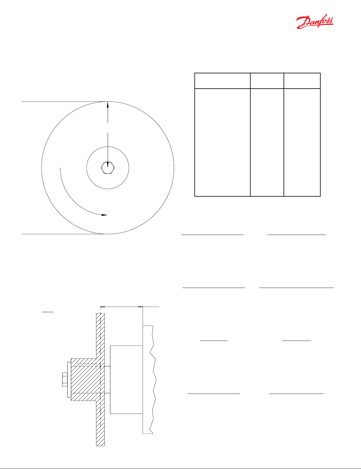
INDUCED SIDE LOAD
Distance
Side Load =
Side Load = 14855 Nm [3333 lbs]
In many cases, pulleys or sprockets may be used to transmit
the torque produced by the motor. Use of these components
will create a torque induced side load on the motor shaft
and bearings. It is important that this load be taken into
consideration when choosing a motor with sufcient bearing
and shaft capacity for the application.
Radius 76 mm [3.00 in]
Torque
1129 Nm
[10000 lb-in]
HYDRAULIC EQUATIONS
Multiplication Factor
12
10
9
10
6
10
3
10
2
10
1
10
-1
10
-2
10
-3
10
-6
10
-9
10
-12
10
-15
10
-18
10
Theo. Speed (RPM) =
Abbrev. Prex
T tera
G giga
M mega
K kilo
h hecto
da deka
d deci
c centi
m milli
u micro
n nano
p pico
f femto
a atto
To determine the side load, the motor torque and pulley or
sprocket radius must be known. Side load may be calculated using the formula below. The distance from the pul-
ley/sprocket centerline to the mounting ange of the motor
must also be determined. These two gures may then be
compared to the bearing and shaft load curve of the desired
motor to determine if the side load falls within acceptable
load ranges.
Torque
Radius
1000 x LPM
Displacement (cm
3
/rev)
Theo. Torque (lb-in) =
Bar x Disp. (cm3/rev)
20 pi
Power In (HP) =
Bar x LPM
600
Power Out (HP) =
Torque (Nm) x RPM
9543
or
PSI x Displacement (in3/rev)
or
or
or
231 x GPM
Displacement (in3/rev)
6.28
PSI x GPM
1714
Torque (lb-in) x RPM
63024
10 | © Danfoss | May 2018 BC267979667405en-000101
Page 11
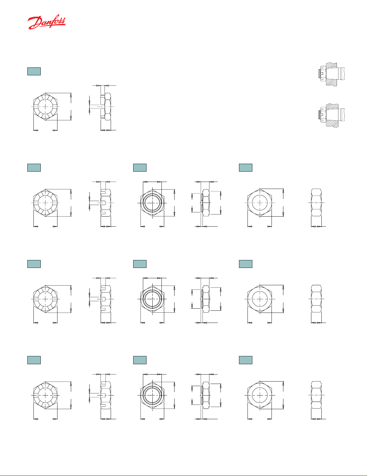
35MM TAPERED SHAFTS
M24 x 1.5
1” T
3/4-28
1-1/4” T
1-20
1-3/8” & 1-1/2” T
1 1/8-18
To
To
12 [.47]
To
14 [.55]
To
15 [.61]
SHAFT NUT INFORMATION
Thread
A Slotted Nut
36 [1.42]
rque Specifications: 32.5 daNm [240 ft.lb.]
APERED SHAFTS
Thread
A Slotted Nut
42 [1.64]
6 [.22]
6 [.24]
15 [.59]
B Lock Nut
PRECAUTION
The tightening torques listed with each nut
should only be used as a guideline. Hubs
may require higher or lower tightening torque
depending on the material. Consult the hub
manufacturer to obtain recommended tightening torque. To maximize torque transfer
from the shaft to the hub, and to minimize
the potential for shaft breakage, a hub with
sufcient thickness must fully engage the
taper length of the shaft.
C Solid Nut
incorrect
correct
rque Specifications: 20 - 23 daNm [150 - 170 ft.lb.]
A Slotted Nut
rque Specifications: 38 daNm [280 ft.lb.] Max.
A Slotted Nut
33 [1.29]
APERED SHAFTS
Thread
44 [1.73]
APERED SHAFTS
Thread
48 [1.90]
5 [.19]
5 [.19]
5 [.19]
6 [.24]
12 [.48]
29 [1.13]28 [1.12]
Torque Specifications: 24 - 27 daNm [180 - 200 ft.lb.]
23 [.92]
33 [1.29]
24 [.95]
B Lock Nut
6 [.25]
14 [.55]
35 [1.38]38 [1.48]
Torque Specifications: 33 - 42 daNm [240 - 310 ft.lb.]
29 [1.14]
40 [1.57]
30 [1.18]
B Lock Nut
6 [.22]
35 [1.38]
51 [2.00]
36 [1.42]
16 [.63]
28 [1.10]
3.5 [.14]
16 [.63]
34 [1.34]
4 [.16]
16 [.63]
44 [1.73]
33 [1.28]
28 [1.11]
Torque Specifications: 20 - 23 daNm [150 - 170 ft.lb.]
C Solid Nut
44 [1.73]
38 [1.48]
Torque Specifications: 38 daNm [280 ft.lb.] Max.
C Solid Nut
48 [1.90]
15 [.61]
rque Specifications: 41 - 54 daNm [300 - 400 ft.lb.]
44 [1.73]42 [1.66]
Torque Specifications: 34 - 48 daNm [250 - 350 ft.lb.]
4 [.16]
42 [1.66]
Torque Specifications: 41 - 54 daNm [300 - 400 ft.lb.]
BC267979667405en-000101 | 11© Danfoss | May 2018
Page 12

SPEED SENSORS
Danfoss offers both single and dual element speed sensor
options providing a number of benets to users by incorporating the latest advancements in sensing technology and
materials. The 700 & 800 series motors single element sensors provide 60 pulses per revolution with the dual element
providing 120 pulses per revolution, with all other series
providing 50 & 100 pulses respectively. Higher resolution
is especially benecial for slow speed applications, where
more information is needed for smooth and accurate control.
The dual sensor option also provides a direction signal allowing end-users to monitor the direction of shaft rotation .
Unlike competitive designs that breach the high pressure
area of the motor to add the sensor, the Danfoss speed
sensor option utilizes an add-on ange to locate all sensor
components outside the high pressure operating environ-
ment. This eliminates the potential leak point common to
competitive designs. Many improvements were made to
the sensor ange including changing the material from
cast iron to acetal resin, incorporating a Buna-N shaft seal
internal to the ange, and providing a grease zerk, which
allows the user to ll the sensor cavity with grease. These
improvements enable the ange to withstand the rigors of
harsh environments.
Another important feature of the new sensor ange is that it
is self-centering, which allows it to remain concentric to the
magnet rotor. This produces a consistent mounting location
for the new sensor module, eliminating the need to adjust
the air gap between the sensor and magnet rotor. The o-
ring sealed sensor module attaches to the sensor ange
with two small screws, allowing the sensor to be serviced
or upgraded in the eld in under one minute. This feature is
especially valuable for mobile applications where machine
downtime is costly. The sensor may also be serviced without
exposing the hydraulic circuit to the atmosphere. Another
advantage of the self-centering ange is that it allows users
to rotate the sensor to a location best suited to their application. This feature is not available on competitive designs,
which x the sensor in one location in relationship to the
motor mounting ange.
FEATURES / BENEFITS
Grease tting allows sensor cavity to be lled with
•
grease for additional protection.
Internal extruder seal protects against environmental
•
elements.
M12 or weatherpack connectors provide installation
•
exibility.
Dual element sensor provides up to 120 pulses per
•
revolution and directional sensing.
Modular sensor allows quick and easy servicing.
•
Acetal resin ange is resistant to moisture, chemi-
•
cals, oils, solvents and greases.
Self-centering design eliminates need to set magnet-
•
to-sensor air gap.
Protection circuitry
•
SENSOR OPTIONS
Z - 4-pin M12 male connector
This option has 50 pulses per revolution on all series except
the DT which has 60 pulses per revolution. This option will
not detect direction.
Y - 3-pin male weatherpack connector*
This option has 50 pulses per revolution on all series except
the DT which has 60 pulses per revolution. This option will
not detect direction.
X - 4-pin M12 male connector
This option has 100 pulses per revolution on all series
except the DT which has 120 pulses per revolution. This
option will detect direction.
W - 4-pin male weatherpack connector*
This option has 100 pulses per revolution on all series
except the DT which has 120 pulses per revolution. This
option will detect direction.
*These options include a 610mm [2 ft] cable.
12 | © Danfoss | May 2018 BC267979667405en-000101
Page 13

SPEED SENSORS
PIN
Z Option
SINGLE ELEMENT SENSOR - Y & Z
Supply voltages ................................................7.5-24 Vdc
Maximum output off voltage .......................................24 V
Maximum continuous output current .................... < 25 ma
Signal levels (low, high) .................... 0.8 to supply voltage
Operating Temp ................-30°C to 83°C [-22°F to 181°F]
DUAL ELEMENT SENSOR - X & W
Supply voltages ................................................7.5-18 Vdc
Maximum output off voltage .......................................18 V
Maximum continuous output current .................... < 20 ma
Signal levels (low, high) .................... 0.8 to supply voltage
Operating Temp ................-30°C to 83°C [-22°F to 181°F]
SENSOR CONNECTORS
• reverse battery protection
• overvoltage due to power supply spikes and
surges (60 Vdc max.)
• power applied to the output lead
The protection circuit feature will help “save” the sensor
from damage mentioned above caused by:
• faulty installation wiring or system repair
• wiring harness shorts/opens due to equipment
failure or harness damage resulting from
accidental conditions (i.e. severed or grounded
wire, ice, etc.)
• power supply spikes and surges caused by other
electrical/electronic components that may be
intermittent or damaged and “loading down” the
system.
1 positive brown or red
1
2
3
2 n/a white
4
3 negative blue
4 pulse out black
X Option
PIN
1 positive brown or red
1
2
3
2 direction out white
4
3 negative blue
4 pulse out black
Y Option
PIN
A positive brown or red
B negative blue
C pulse out black
CBA
W Option
D n/a white
PIN
A positive brown or red
B negative blue
C pulse out black
CDBA
PROTECTION CIRCUITRY
D direction out white
The single element sensor has been improved and incorporates protection circuitry to avoid electrical damage
caused by:
While no protection circuit can guarantee against any and
all fault conditions. The single element sensor from Danfoss
with protection circuitry is designed to handle potential
hazards commonly seen in real world applications.
Unprotected versions are also available for operation at
lower voltages down to 4.5V.
FREE TURNING ROTOR
The ‘AC’ option or “Free turning” option refers to a specially
prepared rotor assembly. This rotor assembly has increased
clearance between the rotor tips and rollers allowing it to
turn more freely than a standard rotor assembly. For spool
valve motors, additional clearance is also provided between
the shaft and housing bore. The ‘AC’ option is available for
all motor series and displacements.
There are several applications and duty cycle conditions
where ‘AC’ option performance characteristics can be
benecial. In continuous duty applications that require high
ow/high rpm operation, the benets are twofold. The ad-
ditional clearance helps to minimize internal pressure drop
at high ows. This clearance also provides a thicker oil lm
at metal to metal contact areas and can help extend the
life of the motor in high rpm or even over speed conditions.
The ‘AC’ option should be considered for applications that
require continuous operation above 57 LPM [15 GPM] and/
or 300 rpm. Applications that are subject to pressure spikes
due to frequent reversals or shock loads can also benet
by specifying the ‘AC’ option. The additional clearance
serves to act as a buffer against spikes, allowing them to
be bypassed through the motor rather than being absorbed
and transmitted through the drive link to the output shaft.
The trade-off for achieving these benets is a slight loss of
volumetric efciency at high pressures.
BC267979667405en-000101 | 13© Danfoss | May 2018
Page 14

INTERNAL DRAIN
The internal drain is an option available on all HB, DR,
and DT Series motors, and is standard on all WP, WR,
WS, and D9 series motors. Typically, a separate drain line
must be installed to direct case leakage of the motor back
to the reservoir when using a HB, DR, or DT Series motor.
However, the internal drain option eliminates the need for
a separate drain line through the installation of two check
valves in the motor endcover. This simplies plumbing
requirements for the motor.
The two check valves connect the case area of the motor to
each port of the endcover. During normal motor operation,
pressure in the input and return lines of the motor close the
check valves. However, when the pressure in the case of
the motor is greater than that of the return line, the check
valve between the case and low pressure line opens, al-
lowing the case leakage to ow into the return line. Since
the operation of the check valves is dependent upon a
pressure differential, the internal drain option operates in
either direction of motor rotation.
Although this option can simplify many motor installations,
precautions must be taken to insure that return line pressure remains below allowable levels (see table below) to
insure proper motor operation and life. If return line pressure
is higher than allowable, or experiences pressure spikes,
this pressure may feed back into the motor, possibly caus-
ing catastrophic seal failure. Installing motors with internal
drains in series is not recommended unless overall pressure drop over all motors is below the maximum allowable
backpressure as listed in the chart below. If in doubt, contact
your authorized Danfoss representative.
MAXIMUM ALLOWABLE
BACK PRESSURE
Series Cont. bar [psi] Inter. bar [psi]
HB 69 [1000] 103 [1500]
DR 69 [1000] 103 [1500]
DT 21 [300] 34 [500]
D9 21 [300] 21 [300]
Brakes 34 [500] 34 [500]
HYDRAULIC DECLUTCH
The declutch or ‘AE’ option, available on the RE and CE
Series motors, has been specically designed for applications requiring the motor to have the ability to “freewheel”
when not pressurized. By making minor changes to internal
components, the torque required to turn the output shaft is
minimal. Selection of this option allows freewheeling speeds
up to 1,000 RPM* depending on the displacement of the
motor and duty cycle of the application.
To enable the motor to perform this function, the standard
rotor assembly is replaced with a freeturn rotor assembly.
Next, the standard balance plate and endcover is replaced
with a special wear plate and ported endcover. The wear
plate features seven holes that connect the stator pockets
to each other. The ported endcover features a movable
piston capable of sealing the seven holes in the wear plate.
When standard motor function is required, pressure is
supplied to the endcover port, moving the piston against
the wear plate. This action seals the seven holes allowing
the motor to function as normal. However, when pressure
is removed from the endcover port, the pressure created
by the turning rotor assembly pushes the piston away from
the wear plate, opening the rotor pockets to each other. In
this condition, oil may circulate freely within the rotor and
endcover assemblies, allowing the rotor assembly to rotate
freely within the motor.
This option is especially
useful in applications
ranging from winch
drives to towable wheel
drives. Depending on
the valves and hydraulic circuitry, operation of
the freewheel function
may be manually or
automatically selected.
A basic schematic is
shown to the right.
The 1,000 RPM rating was based on smaller displacement options with forced ow ushing
through the motor to provide cooling.
14 | © Danfoss | May 2018 BC267979667405en-000101
Page 15

VALVE CAVITY
The valve cavity option provides a cost effective way to
incorporate a variety of cartridge valves integral to the motor. The valve cavity is a standard 10 series (12 series on
the 800 series motor) 2-way cavity that accepts numerous
cartridge valves, including overrunning check valves, relief
cartridges, ow control valves, pilot operated check fuses,
and high pressure shuttle valves. Installation of a relief cartridge into the cavity provides an extra margin of safety for
applications encountering frequent pressure spikes. Relief
cartridges from 69 to 207 bar [1000 to 3000 psi] may also
be factory installed.
SLINGER SEAL
Slinger seals are available on select series offered by
Danfoss. Slinger seals offer extendes shaft/shaft seal
protection by prevented a buildup of material around the
circumference of the shaft which can lead to premature shaft
seal failures. The Danfoss slinger seals are designed to
be larger in diameter than competitive products, providing
greater surface speed and ‘slinging action’.
For basic systems with xed displacement pumps, either
manual or motorized ow control valves may be installed
into the valve cavity to provide a simple method for controlling motor speed. It is also possible to incorporate the
speed sensor option and a programmable logic controller
with a motorized ow control valve to create a closed loop,
fully automated speed control system. For motors with
internal brakes, a shuttle valve cartridge may be installed
into the cavity to provide a simple, fully integrated method
for supplying release pressure to the pilot line to actuate an
integral brake. To discuss other alternatives for the valve
cavity option, contact an authorized Danfoss distributor.
Slinger seals are also available on 4-hole ange mounts
on select series. Contact a Danfoss Customer Service
Representative for additional information.
BC267979667405en-000101 | 15© Danfoss | May 2018
Page 16

RE
750 748 [45.6] 100 130 76 [20] 91 [24] 1062 [9400] 1237 [10950] 103 [1500] 121 [1750] 138 [2000]
C
(All Series)
For Medium Duty Applications
OVERVIEW
RE Series motors offer the perfect compromise between
price and performance by producing work horse power at
a reasonable cost. Although these motors perform well in
a wide range of applications, they are especially suited
for low ow, high pressure applications. During startup,
pressure causes the balance plate to ex toward the rotor,
vastly improving volumetric efciency. As the motor reaches
operating pressure, the balance plate relaxes, allowing the
rotor to turn freely which translates into higher mechanical
efciencies. Transmitting this power to the output shaft is
the most durable drive link in its class. Four bearing options, combined with standard mounting anges and output
shafts, allow the motor to be congured to suit nearly any
application.
FEATURES / BENEFITS
•
High Pressure Shaft Seal offers superior seal life and
performance and eliminates need for case drain.
Three Bearing Options allow load carrying capability of
•
motor to be matched to application.
Heavy-Duty Drive Link is the most durable in its class
•
and receives full ow lubrication to provide long life.
Valve-In-Rotor Design provides cost effective, efcient
•
distribution of oil and reduces overall motor length.
SERIES DESCRIPTIONS
505/506 - Hydraulic Motor
Standard
530/531 - Hydraulic Motor
With Heavy Duty Bearing
540/541 - Hydraulic Motor
With Wheel Hub
520/521 - Hydraulic Motor
With Medium Duty Bearing
535/536 - Hydraulic Motor
Compact, Heavy Duty Bearing
Pressure-Compensated Balance Plate improves volu-
metric efciency at low ows and high pressure.
TYPICAL APPLICATIONS
Medium-duty wheel drives, augers, mixers, winch drives,
swing drives, grapple heads, feed rollers, broom drives
and more
SPECIFICATIONS
ODE Displacement
120 121 [7.4] 360 490 45 [12] 61 [16] 327 [2900] 383 [3400] 207 [3000] 241 [3500] 276 [4000]
160 162 [9.9] 370 470 61 [16] 76 [20] 475 [4200] 542 [4800] 207 [3000] 241 [3500] 276 [4000]
200 204 [12.4] 300 370 68 [18] 83 [22] 542 [4800] 633 [5600] 207 [3000] 241 [3500] 276 [4000]
230 232 [14.2] 260 320 68 [18] 83 [22] 644 [5700] 712 [6300] 207 [3000] 241 [3500] 276 [4000]
260 261 [15.9] 260 350 76 [20] 91 [24] 712 [6300] 791 [7000] 207 [3000] 241 [3500] 276 [4000]
300 300 [18.3] 250 320 83 [22] 95 [25] 825 [7300] 938 [8300] 207 [3000] 241 [3500] 276 [4000]
350 348 [21.2] 220 270 83 [22] 95 [25] 921 [8150] 1045 [9250] 207 [3000] 241 [3500] 276 [4000]
375 375 [22.8] 200 250 76 [20] 91 [24] 1006 [8900] 1158 [10250] 207 [3000] 241 [3500] 276 [4000]
470 465 [28.3] 160 200 76 [20] 91 [24] 1096 [9700] 1184 [10475] 172 [2500] 189 [2750] 207 [3000]
540 536 [32.7] 140 170 76 [20] 91 [24] 983 [8700] 1243 [11000] 138 [2000] 173 [2500] 207 [3000]
620 631 [38.5] 120 150 76 [20] 91 [24] 1014 [8976] 1291 [11421] 121 [1750] 155 [2250] 173 [2500]
Performance data is typical. Performance of production units varies slightly from one motor to another. Running at intermittent ratings should not exceed 10% of every
minute of operation.
16 | © Danfoss | May 2018 BC267979667405en-000101
Max. Speed Max. Flow Max. Torque Max. Pressure
rpm lpm [gpm] Nm [lb-in] bar [psi]
cm3 [in3/rev]
cont. inter. cont. inter. cont. inter. cont. inter. peak
Page 17

DISPLACEMENT PERFORMANCE
Max.
Max.
Theoretical rpm
Displacement tested at 54°C [129°F] with an oil viscosity of 46cSt [213 SUS]
Max. Inter.Max. Cont.Pressure - bar [psi]
mm [in]
7
21
45
92
3
18
43
90
138
186
232
279
3
17
41
86
134
182
230
279
326
372
419
466
3
16
39
84
131
179
229
272
323
372
417
465
2
14
37
82
127
173
222
270
317
364
416
462
1
13
35
80
122
170
220
264
311
361
407
453
9
32
76
121
167
213
255
304
357
401
443
28
72
118
163
207
247
299
350
[326]
[264]
[317]
[342]
37
30
36
39
[685]
[704]
[711]
[664]
[631]
[596]
[640]
[596]
77
80
80
75
71
67
72
67
[1323]
[1448]
[1423]
[1510]
[1395]
[1449]
[1323]
[1275]
[1190]
[1087]
[952]
[929]
149
164
161
171
158
164
149
144
135
123
108
105
[1977]
[2158]
[2143]
[2241]
[2078]
[2090]
[2074]
[1998]
[2022]
[1889]
[1764]
[1726]
223
244
242
253
235
236
234
226
228
213
199
195
[2741]
[2865]
[2792]
[2838]
[2806]
[2760]
[2736]
[2689]
[2739]
[2634]
[2501]
[2476]
310
324
316
321
317
312
309
304
310
298
283
280
[3088]
[3344]
[3350]
[3351]
[3447]
[3411]
[3329]
[3270]
[3317]
[3253]
[3201]
[3092]
349
378
379
379
389
385
376
369
375
368
362
349
[3909]
[4258]
[3992]
[4088]
[4033]
[4022]
[3890]
[4040]
[3847]
[3708]
[4008]
442
481
451
462
456
455
440
457
435
419
453
[4880]
[4569]
[4586]
[4537]
[4623]
[4397]
[4789]
[4439]
551
516
518
513
522
497
541
502
Torque - Nm [lb-in], Speed rpm
Flow - lpm [gpm]
17 [250] 35 [500] 69 [1000] 104 [1500] 138 [2000] 173 [2500] 207 [3000] 241 [3500]
45 [394] 89 [788] 178 [1576] 267 [2365] 356 [3153] 445 [3941] 534 [4729] 623 [5518]
Theoretical Torque - Nm [lb-in]
Max.
Inter.
Max.
Cont.
160
2 [0.5]
4 [1]
8 [2]
15 [4]
23 [6]
30 [8]
38 [10]
45 [12]
53 [14]
61 [16]
68 [18]
76 [20]
12
24
47
94
140
187
234
280
327
374
420
467
Theoretical rpm
Overall Efficiency -
70 - 100% 40 - 69%
0 - 39%
Intermittent Ratings - 10% of Operation
Displacement tested at 54°C [129°F] with an oil viscosity of 46cSt [213 SUS]
Max. Inter.Max. Cont.Pressure - bar [psi]
162 cm
3
[9.9 in3] / rev
mm [in]
Rotor
Width
13.8
[.542]
RE
(All Series)
For Medium Duty Applications
120
121 cm3 [7.4 in3] / rev
2 [0.5]
4 [1]
8 [2]
Flow - lpm [gpm]
15 [4]
23 [6]
30 [8]
38 [10]
45 [12]
Cont.
53 [14]
61 [16]
Inter.
Rotor
Width
13.8
[.542]
17 [250] 35 [500] 69 [1000] 104 [1500] 138 [2000] 173 [2500] 207 [3000] 241 [3500]
Torque - Nm [lb-in], Speed rpm
[187]
21
14
[215]
24
26
Overall Efficiency -
Theoretical Torque - Nm [lb-in]
33 [295] 67 [589] 133 [1178] 200 [1768] 266 [2357] 333 [2946] 399 [3535] 466 [4124]
51
54
57
54
49
111
174
[448]
13
[474]
25
[500]
58
[479]
[433]
97
111
118
116
116
111
104
99
91
84
70 - 100%
[859]
11
[986]
25
[1043]
53
[1030]
106
[1023]
167
[984]
245
[923]
294
[872]
358
[807]
415
[745]
487
[1239]
140
8
[1429]
162
20
[1554]
176
51
[1642]
186
97
[1483]
168
155
[1497]
169
214
[1469]
166
281
[1428]
161
344
[1372]
155
413
[1283]
145
475
40 - 69%
225
226
237
232
223
218
217
208
211
[1991]
13
[1997]
44
[2094]
93
[2051]
150
[1973]
205
[1930]
269
[1918]
331
[1845]
398
[1864]
457
0 - 39%
271
278
279
283
272
276
267
272
Intermittent Ratings - 10% of Operation
[2400]
40
[2459]
89
[2467]
144
[2505]
200
[2411]
261
[2444]
326
[2363]
391
[2403]
447
302
335
328
326
325
321
338
327
[2673]
35
[2964]
85
[2903]
139
[2884]
197
[2878]
250
[2839]
321
[2992]
369
[2897]
427
343
359
360
385
385
385
[3036]
27
[3179]
79
[3185]
137
[3404]
188
[3404]
242
[3403]
304
16
32
63
125
188
250
313
375
438
500
Performance data is typical.
Performance of production
units varies slightly from one
motor to another. Operating at
maximum continuous pressure
and maximum continuous
flow simultaneously is not
recommended. For additional
information on product testing
please refer to page 6.
BC267979667405en-000101 | 17© Danfoss | May 2018
Page 18

RE
Max.
Max.
Theoretical rpm
Displacement tested at 54°C [129°F] with an oil viscosity of 46cSt [213 SUS]
Max. Inter.Max. Cont.Pressure - bar [psi]
mm [in]
Max.
Max.
Theoretical rpm
Displacement tested at 54°C [129°F] with an oil viscosity of 46cSt [213 SUS]
Max. Inter.Max. Cont.Pressure - bar [psi]
mm [in]
(All Series)
For Medium Duty Applications
DISPLACEMENT PERFORMANCE
200
204 cm3 [12.4 in3] / rev
2 [0.5]
4 [1]
8 [2]
Flow - lpm [gpm]
15 [4]
23 [6]
30 [8]
38 [10]
45 [12]
53 [14]
61 [16]
68 [18]
Cont.
76 [20]
83 [22]
Inter.
Rotor
Width
17.3
[.682]
17 [250] 35 [500] 69 [1000] 104 [1500] 138 [2000] 173 [2500] 207 [3000] 241 [3500]
Torque - Nm [lb-in], Speed rpm
[358]
40
7
[376]
43
16
[385]
44
34
[347]
39
72
Overall Efficiency -
Theoretical Torque - Nm [lb-in]
56 [494] 112 [987] 223 [1975] 335 [2962] 446 [3949] 558 [4936] 669 [5924] 781 [6911]
91
85
93
94
82
80
66
13
31
69
111
148
185
[808]
4
[753]
[851]
[834]
[724]
[704]
[581]
133
200
195
198
191
188
180
165
150
134
121
110
70 - 100%
[1181]
4
[1769]
12
[1727]
29
[1752]
67
[1694]
109
[1661]
145
[1592]
181
[1462]
221
[1328]
257
[1183]
296
[1068]
334
[970]
372
[2602]
294
4
[2442]
276
11
[2646]
299
27
[2701]
305
63
[2518]
284
107
[2518]
285
141
[2445]
276
176
[2312]
261
214
[2413]
273
256
[2242]
253
292
[2056]
232
330
[1823]
206
372
[1689]
191
407
40 - 69%
375
373
374
401
389
402
364
362
368
335
339
308
285
[3323]
3
[3304]
10
[3311]
27
[3549]
60
[3446]
103
[3556]
136
[3224]
173
[3200]
210
[3253]
247
[2969]
284
[3003]
327
[2725]
365
[2520]
403
0 - 39%
442
461
477
463
458
458
450
449
435
416
401
379
Intermittent Ratings - 10% of Operation
[3915]
9
[4079]
25
[4222]
58
[4098]
100
[4053]
134
[4051]
170
[3982]
207
[3975]
244
[3850]
277
[3686]
320
[3552]
357
[3353]
397
526
542
544
553
543
535
535
558
524
512
507
486
[4656]
6
[4792]
23
[4818]
55
[4894]
99
[4802]
130
[4737]
164
[4731]
198
[4936]
241
[4639]
273
[4532]
313
[4484]
352
[4303]
388
616
629
636
628
615
618
602
598
599
[5451]
20
[5568]
51
[5628]
90
[5554]
124
[5441]
160
[5471]
196
[5328]
235
[5292]
269
[5299]
308
10
19
38
75
112
150
187
224
261
299
336
373
410
230
233 cm3 [14.2 in3] / rev
2 [0.5]
4 [1]
8 [2]
Flow - lpm [gpm]
15 [4]
23 [6]
30 [8]
38 [10]
45 [12]
53 [14]
61 [16]
68 [18]
Cont.
76 [20]
83 [22]
Inter.
Rotor
Width
19.7
[.777]
17 [250] 35 [500] 69 [1000] 104 [1500] 138 [2000] 173 [2500] 207 [3000] 241 [3500]
Torque - Nm [lb-in], Speed rpm
[397]
45
6
[429]
48
14
[453]
51
30
[384]
43
63
Overall Efficiency -
Theoretical Torque - Nm [lb-in]
64 [565] 128 [1131] 256 [2261] 383 [3392] 511 [4522] 639 [5653] 767 [6783] 894 [7914]
101
105
108
102
92
89
78
12
27
59
93
127
161
[813]
4
[890]
[926]
[960]
[603]
[789]
[690]
184
223
215
209
213
207
198
189
177
150
142
122
70 - 100%
[1628]
3
[1972]
11
[1899]
25
[1851]
55
[1889]
88
[1830]
122
[1750]
157
[1669]
191
[1565]
224
[1326]
256
[1261]
292
[1083]
324
[2590]
293
2
[2793]
316
11
[2911]
329
25
[2884]
326
54
[3001]
339
85
[2793]
316
120
[2752]
311
151
[2624]
296
186
[2596]
293
216
[2408]
272
255
[2333]
264
286
[2096]
237
321
[1855]
210
357
40 - 69%
375
414
425
435
428
425
436
425
388
397
355
347
338
[3323]
1
[3660]
9
[3760]
23
[3846]
52
[3789]
82
[3762]
115
[3856]
148
[3764]
182
[3434]
214
[3509]
249
[3140]
282
[3068]
316
[2987]
351
0 - 39%
493
524
539
536
521
527
510
495
484
493
453
464
Intermittent Ratings - 10% of Operation
[4366]
7
[4637]
20
[4771]
47
[4747]
77
[4612]
110
[4660]
143
[4517]
176
[4384]
208
[4280]
245
[4366]
276
[4009]
309
[4104]
345
560
618
655
628
639
612
599
587
574
569
571
550
[4955]
4
[5468]
17
[5799]
42
[5559]
73
[5653]
107
[5420]
140
[5304]
170
[5197]
205
[5077]
237
[5032]
274
[5057]
305
[4864]
339
710
721
718
717
703
689
680
669
655
[6286]
12
[6381]
39
[6355]
69
[6341]
98
[6218]
132
[6098]
163
[6017]
198
[5925]
227
[5799]
259
9
17
33
66
98
131
163
196
228
261
293
326
358
Performance data is typical.
Performance of production
units varies slightly from one
motor to another. Operating at
maximum continuous pressure
and maximum continuous
flow simultaneously is not
recommended. For additional
information on product testing
please refer to page 6.
18 | © Danfoss | May 2018 BC267979667405en-000101
Page 19

DISPLACEMENT PERFORMANCE
Max.
Max.
Theoretical rpm
Displacement tested at 54°C [129°F] with an oil viscosity of 46cSt [213 SUS]
Max. Inter.Max. Cont.Pressure - bar [psi]
mm [in]
Max. Inter.
Max.
Max.
Theoretical rpm
Displacement tested at 54°C [129°F] with an oil viscosity of 46cSt [213 SUS]
Max. Cont.Pressure - bar [psi]
mm [in]
RE
(All Series)
For Medium Duty Applications
260
261 cm3 [15.9 in3] / rev
2 [0.5]
4 [1]
8 [2]
Flow - lpm [gpm]
15 [4]
23 [6]
30 [8]
38 [10]
45 [12]
53 [14]
61 [16]
68 [18]
76 [20]
Cont.
83 [22]
91 [24]
Inter.
Rotor
Width
22.1
[.872]
17 [250] 35 [500] 69 [1000] 104 [1500] 138 [2000] 173 [2500] 207 [3000] 241 [3500]
Torque - Nm [lb-in], Speed rpm
[432]
49
5
[475]
54
12
[474]
54
27
[429]
49
57
[397]
45
86
Overall Efficiency -
Theoretical Torque - Nm [lb-in]
72 [633] 143 [1266] 286 [2532] 429 [3798] 572 [5064] 715 [6330] 858 [7596] 1001 [8861]
[989]
112
2
[998]
113
115
114
115
94
85
78
64
240
11
[1021]
247
25
[1010]
261
55
[1016]
236
83
[833]
227
114
[752]
231
145
[692]
217
173
[563]
198
202
182
160
136
132
82
70 - 100% 40 - 69%
[2125]
10
[2184]
24
[2307]
51
[2090]
80
[2008]
109
[2044]
144
[1919]
173
[1754]
202
[1608]
231
[1417]
261
[1204]
290
[1168]
319
[722]
348
365
367
363
364
348
340
354
326
299
304
278
263
227
[3230]
9
[3244]
22
[3214]
51
[3221]
78
[3078]
109
[3013]
141
[3135]
168
[2886]
200
[2644]
229
[2693]
261
[2460]
289
[2325]
319
[2009]
347
478
488
486
497
477
470
464
445
448
417
391
374
361
[4227]
8
[4318]
21
[4300]
48
[4398]
76
[4224]
105
[4155]
138
[4108]
166
[3941]
196
[3965]
221
[3690]
256
[3464]
285
[3314]
315
[3190]
345
0 - 39%
578
591
595
590
592
585
567
568
552
550
521
512
496
Intermittent Ratings - 10% of Operation
[5112]
7
[5230]
19
[5268]
46
[5225]
71
[5239]
101
[5180]
133
[5018]
161
[5026]
184
[4884]
219
[4870]
247
[4614]
277
[4535]
311
[4386]
340
648
703
697
721
692
685
672
668
651
643
636
615
[5736]
5
[6223]
16
[6171]
43
[6379]
68
[6128]
96
[6063]
127
[5945]
153
[5908]
181
[5763]
216
[5689]
240
[5628]
274
[5442]
301
807
802
794
796
802
765
752
740
736
[7143]
39
[7096]
63
[7027]
88
[7048]
119
[7095]
144
[6771]
176
[6659]
209
[6551]
232
[6516]
263
8
15
30
59
88
117
146
175
204
233
262
291
320
349
300
300 cm3 [18.3 in3] / rev
2 [0.5]
4 [1]
8 [2]
Flow - lpm [gpm]
15 [4]
23 [6]
30 [8]
38 [10]
45 [12]
53 [14]
61 [16]
68 [18]
76 [20]
Cont.
83 [22]
91 [24]
95 [25]
Inter.
Rotor
Width
25.4
[1.000]
17 [250] 35 [500] 69 [1000] 104 [1500] 138 [2000] 173 [2500] 207 [3000] 241 [3500]
Torque - Nm [lb-in], Speed rpm
[452]
51
3
[557]
63
11
[551]
62
22
[588]
66
48
[511]
58
75
[405]
46
100
Overall Efficiency -
Theoretical Torque - Nm [lb-in]
82 [729] 165 [1457] 329 [2914] 494 [4371] 659 [5828] 823 [7285] 988 [8742] 1152 [10199]
[839]
95
1
[1282]
145
158
145
140
128
111
92
77
63
302
10
[1400]
308
20
[1281]
316
47
[1241]
290
75
[1136]
305
100
[981]
282
125
[814]
261
150
[684]
245
176
[553]
224
201
201
172
144
119
105
70 - 100% 40 - 69%
[2675]
9
[2722]
19
[2793]
45
[2566]
72
[2699]
99
[2493]
124
[2313]
150
[2165]
175
[1983]
201
[1780]
225
[1522]
251
[1276]
277
[1049]
302
[928]
315
433
437
430
424
391
409
388
391
366
339
327
321
281
262
[3829]
8
[3866]
19
[3805]
43
[3755]
69
[3460]
96
[3623]
121
[3435]
148
[3464]
175
[3243]
199
[2999]
225
[2895]
251
[2836]
276
[2483]
301
[2319]
314
510
571
577
546
571
503
472
530
508
467
480
466
435
434
[4513]
7
[5056]
16
[5107]
38
[4830]
65
[5056]
87
[4447]
115
[4177]
143
[4687]
173
[4498]
192
[4135]
222
[4247]
247
[4127]
269
[3853]
300
[3838]
311
0 - 39%
627
679
680
690
700
683
641
661
633
666
611
575
559
553
Intermittent Ratings - 10% of Operation
[5552]
4
[6011]
13
[6015]
33
[6105]
57
[6199]
82
[6043]
106
[5676]
133
[5848]
163
[5599]
187
[5898]
211
[5410]
240
[5084]
263
[4943]
291
[4894]
307
768
820
801
826
794
783
809
796
804
745
732
703
707
[6796]
9
[7258]
28
[7088]
49
[7313]
71
[7028]
98
[6927]
122
[7157]
151
[7044]
173
[7115]
199
[6596]
232
[6474]
254
[6223]
280
[6257]
294
830
908
946
930
919
881
949
916
899
910
[7346]
5
[8040]
21
[8372]
40
[8233]
62
[8131]
88
[7794]
113
[8398]
138
[8103]
163
[7955]
194
[8051]
217
7
13
26
51
76
101
127
152
177
202
228
253
278
303
316
Performance data is typical.
Performance of production
units varies slightly from one
motor to another. Operating at
maximum continuous pressure
and maximum continuous
flow simultaneously is not
recommended. For additional
information on product testing
please refer to page 6.
BC267979667405en-000101 | 19© Danfoss | May 2018
Page 20

RE
Max. Inter.
Max.
Max.
Theoretical rpm
Displacement tested at 54°C [129°F] with an oil viscosity of 46cSt [213 SUS]
Max. Cont.Pressure - bar [psi]
mm [in]
Max. Inter.Max. Cont.
Max.
Max.
Theoretical rpm
Displacement tested at 54°C [129°F] with an oil viscosity of 46cSt [213 SUS]
Pressure - bar [psi]
mm [in]
(All Series)
For Medium Duty Applications
DISPLACEMENT PERFORMANCE
350
348 cm3 [21.2 in3] / rev
2 [0.5]
4 [1]
8 [2]
Flow - lpm [gpm]
15 [4]
23 [6]
30 [8]
38 [10]
45 [12]
53 [14]
61 [16]
68 [18]
76 [20]
Cont.
83 [22]
91 [24]
95 [25]
Inter.
Rotor
Width
39.4
[1.553]
17 [250] 35 [500] 69 [1000] 104 [1500] 138 [2000] 173 [2500] 207 [3000] 241 [3500]
Torque - Nm [lb-in], Speed rpm
[566]
64
4
[570]
64
10
[607]
69
21
[627]
71
42
[549]
62
64
[472]
53
86
Overall Efficiency -
Theoretical Torque - Nm [lb-in]
95 [844] 191 [1688] 381 [3376] 572 [5064] 763 [6752] 954 [8439] 1144 [10127] 1335 [11815]
[1183]
134
134
145
151
149
139
113
98
86
63
272
4
[1189]
296
9
[1285]
312
20
[1340]
313
41
[1618]
315
63
[1233]
307
85
[1004]
298
108
[869]
265
130
[758]
252
152
[560]
235
173
220
208
179
172
70 - 100% 40 - 69%
[2404]
3
[2619]
8
[2764]
19
[2767]
40
[2788]
62
[2713]
84
[2639]
108
[2346]
129
[2226]
151
[2079]
173
[1948]
195
[1843]
217
[1583]
239
[1526]
261
399
437
462
471
474
459
431
445
422
409
394
375
352
360
369
[3532]
2
[3869]
8
[4092]
18
[4169]
39
[4191]
60
[4058]
82
[3814]
108
[3936]
128
[3738]
150
[3619]
172
[3490]
194
[3320]
216
[3112]
239
[3186]
261
[3264]
271
600
630
630
626
601
581
570
549
571
513
554
534
529
[5308]
18
[5577]
37
[5577]
57
[5537]
79
[5317]
102
[5144]
125
[5044]
147
[4859]
170
[5054]
190
[4544]
214
[4906]
238
[4724]
260
[4682]
270
0 - 39%
742
772
768
768
745
740
723
720
693
683
685
666
647
Intermittent Ratings - 10% of Operation
[6571]
17
[6834]
35
[6796]
54
[6793]
75
[6593]
100
[6552]
117
[6398]
139
[6375]
163
[6134]
187
[6044]
213
[6064]
233
[5890]
256
[5730]
265
855
889
925
928
910
891
881
850
839
835
813
[7569]
14
[7869]
34
[8182]
51
[8210]
69
[8056]
93
[7889]
109
[7794]
133
[7522]
155
[7428]
175
[7385]
195
[7198]
221
993
1032
1051
1062
1044
1031
1012
986
975
958
28
45
65
87
104
120
147
164
188
215
[8785]
[9137]
[9300]
[9399]
[9237]
[9126]
[8952]
[8727]
[8632]
[8482]
6
11
22
44
66
88
109
131
153
175
197
218
240
262
273
375
375 cm3 [22.8 in3] / rev
2 [0.5]
4 [1]
8 [2]
Flow - lpm [gpm]
15 [4]
23 [6]
30 [8]
38 [10]
45 [12]
53 [14]
61 [16]
68 [18]
76 [20]
Cont.
83 [22]
91 [24]
Inter.
Rotor
Width
31.8
[1.252]
17 [250] 35 [500] 69 [1000] 104 [1500] 138 [2000] 173 [2500] 207 [3000] 241 [3500]
Intermittent Ratings - 10% of Operation
[6756]
3
[7399]
12
[7587]
29
[7642]
47
[7476]
65
[7399]
87
[7159]
108
[7036]
128
[6817]
151
[6771]
168
[6549]
191
[6160]
213
[5860]
233
955
989
1011
1009
1007
980
949
934
907
877
840
[8449]
9
[8750]
25
[8951]
40
[8930]
60
[8913]
80
[8674]
98
[8402]
120
[8267]
141
[8026]
161
[7764]
183
[7431]
205
1121
1168
1156
1157
1141
1117
1085
1080
1027
[9923]
20
[10334]
36
[10229]
51
[10235]
71
[10098]
92
[9887]
105
[9605]
130
[9554]
150
[9091]
168
[5652]
5
[6095]
14
[6151]
32
[6155]
52
[6154]
71
[6024]
93
[5711]
113
[5602]
134
[5296]
155
[5282]
177
[4969]
198
[4694]
218
[4523]
239
0 - 39%
763
836
857
864
845
836
809
795
770
765
740
696
662
Torque - Nm [lb-in], Speed rpm
[674]
76
3
[745]
84
8
[724]
82
18
[680]
77
39
[595]
67
60
[508]
57
80
Overall Efficiency -
Theoretical Torque - Nm [lb-in]
103 [908] 205 [1815] 410 [3631] 615 [5446] 821 [7261] 1026 [9076] 1231 [10892] 1436 [12707]
162
171
163
158
149
134
115
93
73
[1432]
7
[1510]
17
[1439]
37
[1398]
59
[1321]
80
[1187]
100
[1013]
121
[819]
141
[646]
161
329
361
358
354
340
322
301
280
261
236
209
178
141
70 - 100%
[2911]
6
[[3196]
16
[3164]
37
[3130]
56
[3010]
78
[2849]
99
[2661]
120
[2475]
140
[2314]
161
[2091]
181
[1851]
202
[1576]
222
[1246]
242
[4337]
490
6
[4754]
537
16
[4756]
537
36
[4661]
527
56
[4512]
510
77
[4383]
495
96
[4249]
480
118
[4218]
477
138
[3797]
429
160
[3843]
434
181
[3396]
384
201
[3309]
374
221
[2822]
319
241
40 - 69%
639
689
695
695
695
681
645
633
598
597
561
530
511
6
11
21
41
61
82
102
122
142
163
183
203
223
244
Performance data is typical.
Performance of production
units varies slightly from one
motor to another. Operating at
maximum continuous pressure
and maximum continuous
flow simultaneously is not
recommended. For additional
information on product testing
please refer to page 6.
20 | © Danfoss | May 2018 BC267979667405en-000101
Page 21

DISPLACEMENT PERFORMANCE
PeakMax. Cont.
Max.
Max.
Theoretical rpm
Displacement tested at 54°C [129°F] with an oil viscosity of 46cSt [213 SUS]
Pressure - bar [psi]
mm [in]
Max. Inter.Max. Cont.
Max.
Max.
Theoretical rpm
Displacement tested at 54°C [129°F] with an oil viscosity of 46cSt [213 SUS]
Pressure - bar [psi]
mm [in]
RE
(All Series)
For Medium Duty Applications
470
465 cm3 [28.3 in3] / rev
2 [0.5]
4 [1]
8 [2]
Flow - lpm [gpm]
15 [4]
23 [6]
30 [8]
38 [10]
45 [12]
53 [14]
61 [16]
68 [18]
76 [20]
Cont.
83 [22]
91 [24]
Inter.
Rotor
Width
39.4
[1.553]
17 [250] 35 [500] 69 [1000] 104 [1500] 138 [2000] 173 [2500] 207 [3000]
Torque - Nm [lb-in], Speed rpm
[823]
93
2
[857]
97
7
[865]
98
15
[834]
94
31
[759]
86
48
[643]
73
64
[464]
52
81
Overall Efficiency -
Theoretical Torque - Nm [lb-in]
127 [1127] 255 [2253] 509 [4506] 764 [6760] 1018 [9013] 1273 [11266] 1528 [13519]
185
203
209
200
193
179
164
141
114
[1635]
1
[1794]
5
[1845]
14
[1774]
30
[1704]
47
[1587]
63
[1455]
80
[1248]
97
[1006]
113
[736]
83
130
[497]
56
146
409
435
444
438
424
407
379
350
322
275
235
202
157
70 - 100%
[3618]
5
[3851]
13
[3932]
28
[3880]
44
[3752]
60
[3597]
78
[3350]
94
[3094]
112
[2846]
129
[2434]
145
[2078]
162
[1790]
179
[1392]
195
[5402]
610
5
[5836]
659
13
[5829]
659
28
[5955]
673
44
[5863]
663
60
[5550]
627
78
[5575]
630
93
[5133]
580
111
[4819]
545
127
[4657]
526
145
[4239]
479
161
[4075]
460
178
[3410]
385
194
40 - 69%
815
855
886
872
857
851
832
802
796
737
706
669
620
Intermittent Ratings - 10% of Operation
[7209]
4
[7563]
12
[7836]
26
[7715]
41
[7586]
57
[7533]
75
[7363]
90
[7101]
108
[7040]
123
[6519]
142
[6249]
158
[5920]
176
[5484]
190
0 - 39%
1025
1066
1073
1098
1067
1067
1013
965
956
917
883
843
[9071]
11
[9434]
23
[9499]
37
[9718]
50
[9444]
68
[9441]
83
[8964]
102
[8538]
119
[8464]
138
[8117]
154
[7811]
170
[7464]
186
1196
1250
1258
1279
1276
1273
1222
1190
1166
1122
[10586]
9
[11062]
21
[11128]
32
[11317]
43
[11288]
61
[11264]
76
[10817]
94
[10528]
113
[10317]
128
[9933]
143
5
9
17
33
49
66
82
98
115
131
147
164
180
196
540
536 cm3 [32.7 in3] / rev
2 [0.5]
4 [1]
8 [2]
Flow - lpm [gpm]
15 [4]
23 [6]
30 [8]
38 [10]
45 [12]
53 [14]
61 [16]
68 [18]
76 [20]
Cont.
83 [22]
91 [24]
Inter.
Rotor
Width
45.5
[1.791]
17 [250] 35 [500] 69 [1000] 104 [1500] 138 [2000] 173 [2500]
Torque - Nm [lb-in], Speed rpm
[921]
104
2
[1111]
126
6
[1189]
134
13
[1058]
120
27
[859]
97
41
[692]
78
56
[523]
59
70
Overall Efficiency -
Theoretical Torque - Nm [lb-in]
147 [1302] 294 [2604] 588 [5207] 883 [7811] 1177 [10414] 1471 [13018]
197
230
240
232
224
213
190
176
139
109
[1748]
2
[2031]
5
[2120]
13
[2055]
27
[1984]
41
[1887]
56
[1678]
70
[1554]
84
[1233]
98
[963]
112
[736]
83
126
467
501
510
505
484
455
438
418
385
356
323
297
215
70 - 100%
[4136]
5
[4436]
12
[4510]
26
[4469]
40
[4285]
55
[4026]
69
[3879]
83
[3703]
97
[3407]
111
[3154]
126
[2861]
140
[2629]
154
[1905]
169
699
755
757
783
750
728
719
682
668
612
603
537
491
40 - 69%
Intermittent Ratings - 10% of Operation
[6183]
5
[6679]
12
[6697]
26
[6930]
40
[6635]
54
[6445]
69
[6360]
83
[6035]
96
[5908]
111
[5417]
125
[5333]
139
[4753]
153
[4349]
168
939
977
988
993
983
959
945
952
899
869
829
792
750
[8310]
5
[8646]
11
[8740]
24
[8787]
38
[8698]
53
[8487]
67
[8360]
80
[8421]
94
[7957]
110
[7694]
124
[7335]
138
[7011]
152
[6639]
168
0 - 39%
1149
1185
1223
1225
1251
1244
1203
1183
1163
1116
1109
[10165]
4
[10484]
10
[10827]
23
[10838]
34
[11075]
48
[11008]
62
[10646]
77
[10467]
91
[10290]
105
[9876]
123
[9816]
134
4
8
15
29
114
128
142
156
170
43
57
71
85
99
Performance data is typical.
Performance of production
units varies slightly from one
motor to another. Operating at
maximum continuous pressure
and maximum continuous
flow simultaneously is not
recommended. For additional
information on product testing
please refer to page 6.
BC267979667405en-000101 | 21© Danfoss | May 2018
Page 22

RE
PeakMax. Cont.
Max.
Max.
Theoretical rpm
Displacement tested at 54°C [129°F] with an oil viscosity of 46cSt [213 SUS]
Pressure - bar [psi]
mm [in]
Max. Inter.Max. Cont.
Max.
Max.
Theoretical rpm
Displacement tested at 54°C [129°F] with an oil viscosity of 46cSt [213 SUS]
Pressure - bar [psi]
mm [in]
(All Series)
For Medium Duty Applications
DISPLACEMENT PERFORMANCE
620
631 cm3 [38.5 in3] / rev
2 [0.5]
4 [1]
8 [2]
Flow - lpm [gpm]
15 [4]
23 [6]
30 [8]
38 [10]
45 [12]
53 [14]
61 [16]
68 [18]
76 [20]
Cont.
83 [22]
91 [24]
Inter.
Rotor
Width
54.0
[2.125]
17 [250] 35 [500] 69 [1000] 104 [1500] 121 [1750] 155 [2250]
Torque - Nm [lb-in], Speed rpm
[1060]
120
2
[1202]
136
5
[1256]
142
11
[1159]
131
23
[982]
111
35
[809]
91
47
[595]
67
59
Overall Efficiency -
Theoretical Torque - Nm [lb-in]
173 [1532] 346 [3064] 692 [6127] 1039 [9191] 1212 [10729] 1559 [13794]
228
264
276
269
260
247
220
203
160
124
91
[2021]
1
[2332]
5
[2445]
11
[2379]
23
[2300]
35
[2184]
47
[1943]
58
[1794]
71
[1419]
83
[1095]
95
[801]
107
535
571
581
575
555
526
504
476
439
407
358
328
247
70 - 100%
[4733]
5
[5055]
11
[5141]
23
[5087]
34
[4914]
46
[4655]
58
[4456]
70
[4213]
81
[3885]
94
[3599]
107
[3172]
119
[2901]
131
[2185]
143
796
853
870
883
855
833
815
778
753
703
675
614
556
40 - 69%
Intermittent Ratings - 10% of Operation
[7048]
4
[7550]
10
[7696]
22
[7811]
34
[7570]
45
[7372]
57
[7208]
70
[6888]
80
[6666]
93
[6223]
106
[5974]
118
[5431]
131
[4922]
142
935
985
1008
1014
1000
972
953
930
895
852
815
759
706
[8275]
3
[8717]
9
[8920]
21
[8976]
33
[8853]
44
[8602]
56
[8437]
69
[8233]
79
[7917]
92
[7537]
105
[7215]
117
[6715]
130
[6249]
141
0 - 39%
1256
1279
1285
1291
1268
1240
1225
1187
1147
1100
[11117]
7
[11320]
17
[11368]
29
[11421]
40
[11225]
52
[10977]
65
[10843]
78
[10509]
90
[10147]
104
[9736]
115
3
6
12
24
36
48
60
72
84
96
108
120
132
144
750
748 cm3 [45.6 in3] / rev
2 [0.5]
4 [1]
8 [2]
Flow - lpm [gpm]
15 [4]
23 [6]
30 [8]
38 [10]
45 [12]
53 [14]
61 [16]
68 [18]
76 [20]
Cont.
83 [22]
91 [24]
Inter.
Rotor
Width
63.5
[2.501]
17 [250] 35 [500] 69 [1000] 104 [1500] 138 [2000]
Torque - Nm [lb-in], Speed rpm
[1299]
147
2
[1379]
156
4
[1403]
158
9
[1350]
153
19
[1194]
135
29
[1008]
114
40
[722]
82
50
[477]
54
60
Overall Efficiency -
Theoretical Torque - Nm [lb-in]
205 [1815] 410 [3631] 821 [7261] 1231 [10892] 1641 [14522]
281
322
339
331
321
304
271
249
197
150
105
62
[2487]
1
[2852]
4
[3003]
9
[2933]
19
[2840]
29
[2690]
40
[2395]
49
[2207]
60
[1739]
70
[1325]
80
[927]
90
[552]
100
652
693
705
697
678
648
616
577
533
494
423
385
302
70 - 100%
Intermittent Ratings - 10% of Operation
[5768]
4
[6134]
9
[6241]
19
[6166]
28
[6002]
39
[5733]
49
[5452]
59
[5104]
69
[4718]
79
[4374]
90
[3741]
100
[3404]
110
[2669]
121
967
1027
1064
1059
1039
1015
983
946
905
860
805
747
670
40 - 69%
[8554]
3
[9088]
8
[9419]
18
[9373]
28
[9197]
38
[8980]
48
[8699]
59
[8372]
68
[8008]
78
[7614]
89
[7123]
99
[6608]
110
[5932]
120
1308
1360
1416
1408
1421
1371
1345
1311
1271
1225
1173
[11571]
3
[12033]
7
[12534]
16
[12462]
26
[12573]
34
[12130]
47
[11902]
56
[11600]
67
[11249]
76
[10843]
88
[10385]
98
0 - 39%
3
6
11
21
102
112
122
31
41
51
61
71
82
92
Performance data is typical.
Performance of production
units varies slightly from one
motor to another. Operating at
maximum continuous pressure
and maximum continuous
flow simultaneously is not
recommended. For additional
information on product testing
please refer to page 6.
22 | © Danfoss | May 2018 BC267979667405en-000101
Page 23

RE
13.5 [.530]
4-HOLE, MAGNET
6-HOLE, SAE
E
ST
OPTIONAL
(505/506 Series)
Medium Duty Hydraulic Motor
HOUSINGS
ANDARD
Ø 106.3 [4.187]
O MOUNT, ALIGNED PORTS
62 [2.43] Max. 66 [2.58] Max.
62 [2.43] Min.
22.5°
13.7 [.539]
13.5 [.530]
VALVE CAVITY
136 [5.35] Max.
Dimensions shown are without paint. Paint thickness can be up to 0.13 [.005].
A31 7/8-14 UNF
18 [.70] Max.
3.0 [.120]
2.8 [.110]
82.6 [3.250]
82.5 [3.247]
A38 G 1/2
3 [.12]
61 [2.39]
2 [.06]
64 [2.52]
II
B
23 [.90]
127.0 [4.999]
126.8 [4.996]
23 [.90]
A
A
B
F
60 [2.35] Min.
114 [4.49]
: 10 Series/2-Way Valve Cavity 7/8-14 UNF F: Valve Cartridge Installed
A MOUNT, ALIGNED PORTS A51 7/8-14 UNF
62 [2.43] Max. 66 [2.58] Max.
62 [2.43] Min.
22.5°
136 [5.35] Max.
82.6 [3.250]
82.5 [3.247]
18 [.70] Max.
3.0 [.120]
2.8 [.110]
A58 G 1/2
61 [2.39]
E
Ø31 [1.24] Spot Face
II
B
23 [.91]
23 [.90]
23 [.90]
127.0 [4.999]
126.8 [4.996]
Ø 106.3 [4.187]
13.7 [.539]
Dimension II is charted on page 25.
A
3 [.12]
2 [.06]
BC267979667405en-000101 | 23© Danfoss | May 2018
Page 24

RE
127.0 [4.999]
126.9 [4.995]
4-HOLE, WHEEL
E
ST
OPTIONAL
(505/506 Series)
Medium Duty Hydraulic Motor
HOUSINGS
ANDARD
13.7 [.539]
13.5 [.530]
MOUNT, ALIGNED PORTS
132 [5.21] Max.
45°
VALVE CAVITY
BA
62 [2.43] Min.
138 [5.45] Max.
Ø 147.6 [5.812]
W31 7/8-14 UNF
82.54 [3.249]
82.50 [3.248]
82.50 [3.248]
82.45 [3.246]
Dimensions shown are without paint. Paint thickness can be up to 0.13 [.005].
W38 G 1/2
44.3 [1.745]
44.2 [1.741]
19 [.76]
5 [.20]
18 [.72]
JJ
37 [1.48]
3 [.10] Min.
B
A
23 [.90]
23 [.90]
F
57 [2.25]
111 [4.37]
: 10 Series/2-Way Valve Cavity 7/8-14 UNF F: Valve Cartridge Installed
Dimension JJ is charted on page 25.
29 [1.14]
E
Ø31 [1.24] Spot Face
24 | © Danfoss | May 2018 BC267979667405en-000101
Page 25

TECHNICAL INFORMATION
MAGNETO & SAE A MOUNTS
3in4-3 21-2 0-1
WHEEL MOUNTS
4in5-2 32-1 10
750
ALLOWABLE SHAFT LOAD / BEARING CURVE LENGTH & WEIGHT CHART
The bearing curve represents allowable bearing loads
based on ISO 281 bearing capacity for an L10 life of 2,000
hours at 100 rpm. Radial loads for speeds other than 100
rpm may be calculated using the multiplication factor table
on page 7.
9000
8000
7000
6000
5000
4000
3000
2000
1000
lb
75 mm1005025-75 -50 0-25
445 daN [1000 lb]
445 daN [1000 lb]
SHAFT
BEARING
4000
3500
3000
2500
2000
1500
1000
500
daN
Dimensions II & JJ are the overall
motor lengths from the rear of the
motor to the mounting ange surface and are referenced on detailed
housing drawings listed on pages
23 & 24.
All RE series motor weights can vary ± 0.5
kg [1 lb] depending on model congurations
such as housing, shaft, endcover, options etc.
RE
(505/506 Series)
Medium Duty Hydraulic Motor
Length Weight
II
#
mm [in]
120
162 [6.37]
160
162 [6.37]
200
165 [6.51]
230
168 [6.61]
260
170 [6.70]
300
174 [6.83]
350
187 [7.38]
375
180 [7.08]
470
187 [7.38]
540
194 [7.62]
620
202 [7.95]
212 [8.33]
Length Weight
JJ
#
mm [in]
120
120 [4.72]
160
120 [4.72]
200
123 [4.86]
230
126 [4.95]
260
128 [5.05]
300
132 [5.18]
350
146 [5.73]
375
138 [5.43]
470
146 [5.73]
540
152 [5.97]
620
161 [6.35]
750
170 [6.68]
kg [lb]
10.6 [23.4]
10.6 [23.4]
11.0 [24.2]
11.1 [24.4]
11.3 [25.0]
11.7 [25.8]
12.8 [28.2]
12.2 [27.0]
12.8 [28.2]
13.3 [29.4]
14.1 [30.9]
14.8 [32.5]
kg [lb]
11.7 [25.8]
11.7 [25.8]
12.1 [26.6]
12.2 [26.8]
12.4 [27.4]
12.8 [28.2]
13.9 [30.6]
13.3 [29.4]
13.9 [30.6]
14.4 [31.8]
15.1 [33.4]
15.8 [34.9]
9000
8000
7000
6000
5000
4000
3000
2000
1000
lb
100 mm1257550-50 -25 250
445 daN [1000 lb]
445 daN [1000 lb]
BEARING
4000
3500
3000
2500
2000
1500
SHAFT
1000
500
daN
BC267979667405en-000101 | 25© Danfoss | May 2018
Page 26

RE
34.8 [1.372]
34.5 [1.359]
35.3 [1.388]
35.0 [1.376]
02
Max. T
Max. T
Max. T
03
10
15
Max. T
25
(505/506 Series)
Medium Duty Hydraulic Motor
SHAFTS
1” 6B Spline
6B Spline
SAE J499 Standard
5/16-18 UNC, Min. Depth 18 [.70]
orque: 678 Nm [6000 lb-in]
07 1-1/4” Straight Extended
8.0 [.314]
8.0 [.313]
31.8 [1.250]
31.7 [1.249]
5/8-18 UNF, Min. Depth 21 [.83]
25 [1.00]
Ø25.3 [.996]
Ø25.2 [.992]
20 1-1/4” Straight
8 [.33]
1” 6B Spline Extended
KK
40 [1.58]
KK
54 [2.14]
48 [1.90]
37.5 [1.475]
36.2 [1.425]
28.2 [1.110]
28.0 [1.101]
Max. Torque: 655 Nm [5800 lb-in]
12 25mm Straight
28.0 [1.102]
27.7 [1.091]
1” Straight
6.4 [.251]
6.4 [.250]
5/16-18 UNC, Min. Depth 18 [.70]
8.0 [.314]
8.0 [.313]
M8x1.25, Min. Depth 16 [.63]
25.9 [1.020]
24.6 [.970]
Ø25.4 [.999]
Ø25.3 [.998]
30.9 [1.218]
29.7 [1.168]
Ø25.0 [.984]
Ø25.0 [.983]
5 [.18]
5 [.21]
1” Straight Extended
KK
40 [1.58]
KK
46 [1.83]
orque: 1200 Nm [10600 lb-in]
08 32mm Straight Extended 21 32mm Straight
KK
54 [2.14]
10.0 [.394]
10.0 [.392]
32.0 [1.260]
32.0 [1.259]
M8x1.25, Min. Depth 16 [.63]
orque: 1200 Nm [10600 lb-in]
09 14 Tooth Spline Extended
14 Tooth Spline 12/24 Pitch
Standard ANSI B92.1-1996 Spline
33 [1.31]
Wire Ring
5/8-18 UNF, Min. Depth 21 [.83] Ø2 [.06]
orque: 1200 Nm [10600 lb-in]
31.7 [1.249]
31.6 [1.245]
12 [.46]
48 [1.90]
23 14 Tooth Spline
KK
54 [2.14]
48 [1.90]
41 [1.60]
32.6 [1.285]
31.4 [1.235]
Max. Torque: 678 Nm [6000 lb-in]
22 1-1/4” Tapered
8.0 [.314]
8.0 [.313]
4 [.15]
Max. Torque: 1200 Nm [10600 lb-in]
5 [.20]
31.8 [1.250]
31.7 [1.249]
MOUNTING / SHAFT LENGTH CHART
Dimension KK is the overall distance from the motor mounting
surface to the end of the shaft and
is referenced on detailed shaft drawings above.
Shaft lengths vary ± 0.8 mm [.030 in.]
25 1-1/4” Tapered Extended
KK
35 [1.37]
19 [.75]
1:8 TaperØ4 [.17]
A slotted hex nut is standard on this
shaft.
KK
#
02
03
07
08
09
10
12
15
20
21
22
23
Magneto &
A Mounts
mm [in]
50 [1.97]
76 [3.01]
88 [3.45]
88 [3.45]
88 [3.45]
50 [1.97]
56 [2.21]
76 [3.01]
61 [2.41]
61 [2.41]
66 [2.58]
61 [2.41]
92 [3.62]
Wheel
Mounts
mm [in]
91 [3.60]
118 [4.64]
129 [5.09]
129 [5.09]
129 [5.09]
91 [3.60]
98 [3.84]
118 [4.64]
103 [4.05]
103 [4.05]
107 [4.22]
103 [4.05]
134 [5.26]
24.3 [.957]
23.0 [.907]
26 | © Danfoss | May 2018 BC267979667405en-000101
Page 27

ORDERING INFORMATION
Extended shafts are designed for use with one of the speed sensor options listed in STEP 7.
1234567 8
1. CHOOSE SERIES DESIGNATION
5. SELECT A PAINT OPTION
RE
(505/506 Series)
Medium Duty Hydraulic Motor
Standard Rotation Reverse Rotation
505
The 505 & 506 series are bi-directional. For applications requiring the motor to rotate in only
one direction, shaft seal life may be prolonged by pressurizing the A port of the motor.
506
2. SELECT A DISPLACEMENT OPTION
3
348 cm
120
121 cm3/rev [7.4 in3/rev]
160
162 cm3/rev [9.9 in3/rev]
200
204 cm3/rev [12.4 in3/rev]
230
232 cm3/rev [14.2 in3/rev]
260
261 cm3/rev [15.9 in3/rev]
300
300 cm3/rev [18.3 in3/rev]
350
375
470
540
620
750
/rev [21.2 in3/rev]
375 cm3/rev [22.8 in3/rev]
465 cm3/rev [28.3 in3/rev]
536 cm3/rev [32.7 in3/rev]
631 cm3/rev [38.5 in3/rev]
748 cm3/rev [45.6 in3/rev]
3. SELECT A MOUNT & PORT OPTION
A31
4-Hole, Magneto Mount, Aligned Ports, 7/8-14 UNF
A38
4-Hole, Magneto Mount, Aligned Ports, G 1/2
A51
6-Hole, SAE A Mount, Aligned Ports, 7/8-14 UNF
A58
6-Hole, SAE A Mount, Aligned Ports, G 1/2
W31
4-Hole, Wheel Mount, Aligned Ports, 7/8-14 UNF
W38
4-Hole, Wheel Mount, Aligned Ports, G 1/2
Speed sensor option is not available with wheel mounts
4. SELECT A SHAFT OPTION
A
Black
B
Black, Unpainted Mounting Surface
Z
No Paint
6. SELECT A VALVE CAVITY / CARTRIDGE OPTION
None
A
Valve Cavity Only
B
69 bar [1000 psi] Relief
C
86 bar [1250 psi] Relief
D
Valve cavity is not available on the A51 & A58 housings.
104 bar [1500 psi] Relief
E
121 bar [1750 psi] Relief
F
138 bar [2000 psi] Relief
G
7. SELECT AN ADD-ON OPTION
A
Standard
B
Lock Nut
C
Solid Hex Nut
W
Speed Sensor, Dual, 4-Pin Male Weatherpack Connector
X
Speed Sensor, Dual, 4-Pin M12 Male Connector
Y
Speed Sensor, Single, 3-Pin Male Weatherpack Connector
Z
Speed Sensor, Single, 4-Pin M12 Male Connector
8. SELECT A MISCELLANEOUS OPTION
AA
None
AC
Freeturning Rotor
AE
Hydraulic Declutch With Freeturning Rotor
02
1” 6B Spline
03
1” 6B Spline Extended
07
1-1/4” Straight Extended
08
32mm Straight Extended
09
14 Tooth Spline Extended
10
1” Straight
12
25mm Straight
1” Straight Extended
15
1-1/4” Straight
20
32mm Straight
21
1-1/4” Tapered
22
14 Tooth Spline
23
1-1/4” Tapered Extended
25
BC267979667405en-000101 | 27© Danfoss | May 2018
Page 28

RE
6-HOLE, SAE
4-HOLE, WHEEL
6-HOLE, SAE
(520/521 Series)
Medium Duty Hydraulic Motor
HOUSINGS
A MOUNT, ALIGNED PORTS
71 [2.80] Max. 66 [2.58] Max.
63 [2.47] Min.
22.5°
13.3 [.524]
13.1 [.514]
A MOUNT, ALIGNED MANIFOLD PORTS A57 1/2” Drilled
63 [2.48] Min.71 [2.80] Max.
22.5°
Ø 106.3 [4.187]
137 [5.38] Max.
2 [.07]
Dimensions shown are without paint. Paint thickness can be up to 0.13 [.005].
A51 7/8-14 UNF
19 [.73] Max.
3.0 [.120]
2.8 [.110]
82.6 [3.250]
82.5 [3.247]
3 [.12]
19 [.73] Max.
3.0 [.120]
2.8 [.110]
A58 G 1/2
LL
86 [3.40]
B
23 [.90]
23 [.90]
A
2 [.06]
LL
86 [3.40]
14 [.56]
14 [.56]
13.3 [.524]
13.1 [.514]
137 [5.38] Max.
17 [.68]
Ø 106.3 [4.187]
MOUNT, ALIGNED PORTS W31 7/8-14 UNF
133 [5.23] Max. 70 [2.76]
13.3 [.524]
13.1 [.514]
22.5°
62 [2.45] Min.
141 [5.56] Max.
Ø 147.6 [5.812]
82.6 [3.250]
82.5 [3.247]
95.3 [3.750]
95.2 [3.748]
64 [2.50]
3 [.12]
2 [.06]
W38 G 1/2
19 [.76]
20 [.78]
89 [3.50]
B
A
(4) M8x1.25, Min. Depth 13 [.50]
MM
37 [1.48]
3 [.10] Min.
B
A
23 [.91]
23 [.91]
23 [.90]
23 [.90]
127.0 [4.999]
126.9 [4.995]
Dimensions LL & MM are charted on page 29.
28 | © Danfoss | May 2018 BC267979667405en-000101
Page 29

TECHNICAL INFORMATION
SAE A MOUNTS
3in4-3 21*2 0-1
WHEEL MOUNTS
5in6-1 43021
750
ALLOWABLE SHAFT LOAD / BEARING CURVE LENGTH & WEIGHT CHART
The bearing curve represents allowable bearing loads
based on ISO 281 bearing capacity for an L10 life of 2,000
hours at 100 rpm. Radial loads for speeds other than 100
rpm may be calculated using the multiplication factor table
Dimensions LL & MM are the overall
motor lengths from the rear of the
motor to the mounting ange surface and are referenced on detailed
housing drawings listed on page 28.
on page 7.
11000
10000
9000
8000
7000
6000
5000
4000
3000
2000
1000
BEARING
lb
75 mm1005025-75 -50 0-25
445 daN [1000 lb]
445 daN [1000 lb]
SHAFT
4500
4000
3500
3000
2500
2000
1500
1000
500
daN
All RE series motor weights can vary ± 0.5
kg [1 lb] depending on model congurations
such as housing, shaft, endcover, options etc.
RE
(520/521 Series)
Medium Duty Hydraulic Motor
Length Weight
LL
#
120
160
200
230
260
300
350
375
470
540
620
MM
#
120
160
200
230
260
300
350
375
470
540
620
750
187 [7.37]
187 [7.37]
191 [7.51]
193 [7.61]
196 [7.70]
199 [7.83]
213 [8.38]
205 [8.08]
213 [8.38]
219 [8.62]
227 [8.95]
237 [9.33]
120 [4.72]
120 [4.72]
123 [4.86]
126 [4.95]
128 [5.05]
132 [5.18]
146 [5.73]
138 [5.43]
146 [5.73]
152 [5.97]
160 [6.30]
170 [6.68]
mm [in]
Length Weight
mm [in]
kg [lb]
13.3 [29.4]
13.3 [29.4]
13.7 [30.2]
13.8 [30.4]
14.1 [31.0]
14.4 [31.8]
15.5 [34.2]
15.0 [33.0]
15.5 [34.2]
16.1 [35.4]
16.8 [36.9]
17.5 [38.5]
kg [lb]
12.9 [28.4]
12.9 [28.4]
13.2 [29.2]
13.3 [29.4]
13.6 [30.0]
14.0 [30.8]
15.1 [33.2]
14.5 [32.0]
15.1 [33.2]
15.6 [34.4]
16.3 [35.9]
17.0 [37.5]
11000
10000
9000
8000
7000
6000
5000
4000
3000
2000
1000
125 mm15010075-25 05025
445 daN [1000 lb]
445 daN [1000 lb]
SHAFT
BEARING
lb
4500
4000
3500
3000
2500
2000
1500
1000
500
daN
BC267979667405en-000101 | 29© Danfoss | May 2018
Page 30

RE
SAE A
Wheel
34.8 [1.372]
34.5 [1.359]
35.3 [1.388]
35.0 [1.376]
03
Max. T
Max. T
09
Max. T
(520/521 Series)
Medium Duty Hydraulic Motor
SHAFTS
1” 6B Spline
6B Spline
SAE J499 Standard
5/16-18 UNC, Min. Depth 18 [.70]
orque: 678 Nm [6000 lb-in]
07 1-1/4” Straight
5/8-18 UNF, Min. Depth 21 [.83]
8.0 [.314]
8.0 [.313]
31.8 [1.250]
31.7 [1.249]
25 [1.00]
Ø25.3 [.996]
Ø25.2 [.992]
8 [.33]
40 [1.58]
NN
54 [2.14]
48 [1.90]
37.5 [1.475]
36.2 [1.425]
NN
14 Tooth Spline
14 Tooth Spline 12/24 Pitch
Standard ANSI B92.1-1996 Spline
33 [1.31]
Wire Ring
Max. Torque: 1200 Nm [10600 lb-in]
15 1” Straight
28.2 [1.110]
28.0 [1.101]
NN
54 [2.14]
48 [1.90]
41 [1.60]
31.7 [1.249]
31.6 [1.245]
5/8-18 UNF, Min. Depth 21 [.83] Ø2 [.06]
40 [1.58]
6.4 [.251]
6.4 [.250]
5/16-18 UNC, Min. Depth 18 [.70]
25.9 [1.020]
24.6 [.970]
5 [.18]
Ø25.4 [.999]
Ø25.3 [.998]
NN
orque: 1200 Nm [10600 lb-in]
08 32mm Straight
10.0 [.394]
10.0 [.392]
M8x1.25, Min. Depth 16 [.63]
orque: 1200 Nm [10600 lb-in]
12 [.46]
32.0 [1.260]
32.0 [1.259]
MOUNTING / SHAFT LENGTH CHART
Dimension NN is the overall distance from the motor mounting
surface to the end of the shaft and
is referenced on detailed shaft drawings above.
Shaft lengths vary ± 0.8 mm [.030 in.]
NN
03
07
08
09
15
25
Max. Torque: 655 Nm [5800 lb-in]
25 1-1/4” Tapered
NN
54 [2.14]
48 [1.90]
Mounts
#
mm [in]
51 [2.02]
63 [2.47]
62 [2.47]
63 [2.47]
51 [2.02]
67 [2.63]
119 [4.69]
131 [5.15]
130 [5.15]
131 [5.15]
119 [4.69]
133 [5.25]
Mounts
mm [in]
32.6 [1.285]
31.4 [1.235]
4 [.15]
Max. Torque: 1200 Nm [10600 lb-in]
8.0 [.314]
8.0 [.313]
5 [.20]
31.8 [1.250]
31.7 [1.249]
NN
35 [1.37]
19 [.75]
1:8 TaperØ4 [.17]
A slotted hex nut is standard on this
shaft.
24.3 [.957]
23.0 [.907]
30 | © Danfoss | May 2018 BC267979667405en-000101
Page 31

ORDERING INFORMATION
1234567 8
1. CHOOSE SERIES DESIGNATION
4. SELECT A SHAFT OPTION
RE
(520/521 Series)
Medium Duty Hydraulic Motor
Standard Rotation Reverse Rotation
520
The 520 & 521 series are bi-directional. For applications requiring the motor to rotate in only
one direction, shaft seal life may be prolonged by pressurizing the A port of the motor.
521
2. SELECT A DISPLACEMENT OPTION
120
121 cm3/rev [7.4 in3/rev]
160
162 cm3/rev [9.9 in3/rev]
200
204 cm3/rev [12.4 in3/rev]
230
232 cm3/rev [14.2 in3/rev]
260
261 cm3/rev [15.9 in3/rev]
300
300 cm3/rev [18.3 in3/rev]
348 cm3/rev [21.2 in3/rev]
350
375 cm3/rev [22.8 in3/rev]
375
465 cm3/rev [28.3 in3/rev]
470
536 cm3/rev [32.7 in3/rev]
540
631 cm3/rev [38.5 in3/rev]
620
748 cm3/rev [45.6 in3/rev]
750
3. SELECT A MOUNT & PORT OPTION
A51
6-Hole, SAE A Mount, Aligned Ports, 7/8-14 UNF
A57
6-Hole, SAE A Mount, Aligned Manifold Ports, 1/2” Drilled
A58
6-Hole, SAE A Mount, Aligned Ports, G 1/2
W31
4-Hole, Wheel Mount, Aligned Ports, 7/8/14 UNF
W38
4-Hole, Wheel Mount, Aligned Ports, G 1/2
03
1” 6B Spline
07
1-1/4” Straight
08
32mm Straight
14 Tooth Spline
09
1” Straight
15
1-1/4” Tapered
25
5. SELECT A PAINT OPTION
A
Black
B
Black, Unpainted Mounting Surface
Z
No Paint
6. SELECT A VALVE CAVITY / CARTRIDGE OPTION
None
A
7. SELECT AN ADD-ON OPTION
A
Standard
B
Lock Nut
C
Solid Hex Nut
8. SELECT A MISCELLANEOUS OPTION
AA
None
AC
Freeturning Rotor
AE
Hydraulic Declutch With Freeturning Rotor
BC267979667405en-000101 | 31© Danfoss | May 2018
Page 32

RE
13.3 [.524]
13.1 [.514]
6-HOLE, SAE
4-HOLE, WHEEL
(530/531 Series)
Medium Duty Hydraulic Motor
HOUSINGS
Dimensions shown are without paint. Paint thickness can be up to 0.13 [.005].
A MOUNT, ALIGNED PORTS
71 [2.80] Max. 66 [2.61] Max.
63 [2.47] Min.
22.5°
13.3 [.524]
13.1 [.514]
137 [5.38] Max.
Ø 106.3 [4.187]
A51 7/8-14 UNF
19 [.73] Max.
3.0 [.120]
2.8 [.110]
82.6 [3.250]
82.5 [3.247]
MOUNT, ALIGNED PORTS T31 7/8-14 UNF T38 G 1/2
45.3 [1.785]
132 [5.21] Max.
63 [2.47] Min.
45.1 [1.775]
26 [1.02]
A58 G 1/2
OO
86 [3.40]
B
23 [.90]
23 [.90]
A
W31 7/8-14 UNF W38 G 1/2
OO
53 [2.07]
6 [.25]
Dimension OO is charted on page 33.
45°
132 [5.21] Max.
Ø 147.6 [5.812]
82.6 [3.250]
82.5 [3.247]
B
A
23 [.90]
23 [.90]
127.0 [4.999]
126.9 [4.995]
32 | © Danfoss | May 2018 BC267979667405en-000101
Page 33

RE
SAE A MOUNTS
3in4-3 21-2 0-1
5in746-2 32-1 10
T31 & T38 WHEEL MOUNTS
W31 & W38 WHEEL MOUNTS
5in46-2 32-1 10
750
17.5 [38.5]
237 [9.33]
206 [8.11]
(530/531 Series)
Medium Duty Hydraulic Motor
TECHNICAL INFORMATION
ALLOWABLE SHAFT LOAD / BEARING CURVE
The bearing curve represents allowable bearing loads based on ISO 281 bearing capacity for an L10 life of 2,000 hours at
100 rpm. Radial loads for speeds other than 100 rpm may be calculated using the multiplication factor table on page 7.
9000
8000
7000
6000
5000
4000
3000
2000
1000
lb
14000
12000
10000
8000
6000
4000
2000
lb
BEARING
75 mm1005025-75 -50 0-25
445 daN [1000 lb]
445 daN [1000 lb]
SHAFT
BEARING
125 mm100 1507550-50 -25 250
445 daN [1000 lb]
445 daN [1000 lb]
SHAFT
4000
3500
3000
2500
2000
1500
1000
500
daN
6000
5000
4000
3000
2000
1000
daN
9000
8000
7000
6000
5000
4000
3000
2000
1000
lb
LENGTH & WEIGHT CHART
Dimension OO is the overall motor
length from the rear of the motor to
the mounting ange surface and
are referenced on detailed housing
drawings listed on page 32.
All RE series motor weights can vary ± 0.5
kg [1 lb] depending on model congurations
such as housing, shaft, endcover, options etc.
OO
#
120
160
200
230
260
300
350
375
470
540
620
125 mm175100 1507550-50 -25 250
445 daN [1000 lb]
445 daN [1000 lb]
BEARING
SAE A
Mounts
mm [in]
187 [7.37]
187 [7.37]
191 [7.51]
193 [7.61]
196 [7.70]
199 [7.83]
213 [8.38]
205 [8.08]
213 [8.38]
219 [8.62]
227 [8.95]
SHAFT
Wheel
Mounts
mm [in]
156 [6.15]
156 [6.15]
159 [6.29]
162 [6.38]
165 [6.48]
168 [6.61]
182 [7.16]
174 [6.86]
182 [7.16]
188 [7.40]
196 [7.77]
4000
3500
3000
2500
2000
1500
1000
500
daN
Weight
kg [lb]
13.3 [29.4]
13.3 [29.4]
13.7 [30.2]
13.8 [30.4]
14.1 [31.0]
14.4 [31.8]
15.5 [34.2]
15.0 [33.0]
15.5 [34.2]
16.1 [35.4]
16.8 [36.9]
BC267979667405en-000101 | 33© Danfoss | May 2018
Page 34

RE
38.0 [1.391]
38.0 [1.389]
27
Max. T
30
Max. T
Max. T
SAE A
Wheel
(530/531 Series)
Medium Duty Hydraulic Motor
SHAFTS
35mm Straight
PP
58 [2.28]
10.0 [.394]
10.0 [.392]
M8x1.25, Min. Depth 18 [.69]
orque: 1200 Nm [10600 lb-in]
6 [.24]
35.0 [1.379]
35.0 [1.378]
45.5 [1.791]
45.0 [1.772]
28 35mm” Tapered
PP
8.0 [.314]
8.0 [.313]
4 [.15]
orque: 1200 Nm [10600 lb-in] Max. Torque: 1200 Nm [10600 lb-in]
3 [.12]
35.0 [1.378]
34.5 [1.358]
Ø5 [.20]
36 [1.42]22 [.87]
22.9 [.900]
22.6 [.890]
1:10 Taper
A slotted hex nut is standard on this
shaft.
M4 1-3/8” Tapered
PP
8.0 [.314]
8.0 [.313]
4 [.15]
5 [.20]
35.1 [1.380]
34.9 [1.375]
41 [1.63]21 [.83]
31.8 [1.250]
30.5 [1.200]
1-1/2” Straight
42.4 [1.671]
42.1 [1.657]
40 [1.58]
Wire Ring
Max. Torque: 1200 Nm [10600 lb-in]
31 1-1/2” Tapered
8.0 [.314]
8.0 [.313]
4 [.15]
MOUNTING / SHAFT LENGTH CHART
Dimension PP is the overall distance from the motor mounting
surface to the end of the shaft and
is referenced on detailed shaft drawings above.
Shaft lengths vary ± 0.8 mm [.030 in.]
9.6 [.376]
9.5 [.375]
10[.39]
38.1 [1.499]
38.0 [1.498]
3/8-16 UNC,
Min. Depth 19 [.75]
5 [.20]
38.1 [1.500]
38.1 [1.499]
Ø4 [.17]
PP
80 [3.07]*
38.9 [1.530]
37.6 [1.480]
* Dimension is 68 [2.67] for wheel mounts
PP
44 [1.72]19 [.75]
31.8 [1.250]
30.5 [1.200]
1:8 Taper
A slotted hex nut is standard on this
shaft.
PP
M4
Mounts
#
mm [in]
27
28
30
87 [3.42]
31
84 [3.32]
83 [3.28]
N/A
N/A
Mounts
mm [in]
104 [3.97]
105 [4.14]
118 [4.63]
115 [4.53]
114 [4.49]
orque: 1200 Nm [10600 lb-in]
Ø4 [.17]
A slotted hex nut is standard on this
shaft.
1:8 Taper
34 | © Danfoss | May 2018 BC267979667405en-000101
Page 35

ORDERING INFORMATION
with
1234567 8
1. CHOOSE SERIES DESIGNATION
4. SELECT A SHAFT OPTION
RE
(530/531 Series)
Medium Duty Hydraulic Motor
Standard Rotation Reverse Rotation
530
The 530 & 531 series are bi-directional. For applications requiring the motor to rotate in only
one direction, shaft seal life may be prolonged by pressurizing the A port of the motor.
531
2. SELECT A DISPLACEMENT OPTION
120
121 cm3/rev [7.4 in3/rev]
162 cm
204 cm
232 cm
261 cm
300 cm
3
3
3
3
3
/rev [9.9 in3/rev]
/rev [12.4 in3/rev]
/rev [14.2 in3/rev]
/rev [15.9 in3/rev]
/rev [18.3 in3/rev]
160
200
230
260
300
348 cm3/rev [21.2 in3/rev]
350
3
/rev [22.8 in3/rev]
375 cm
375
3
465 cm
536 cm
631 cm
748 cm
3
3
3
/rev [28.3 in3/rev]
/rev [32.7 in3/rev]
/rev [38.5 in3/rev]
/rev [45.6 in3/rev]
470
540
620
750
3. SELECT A MOUNT & PORT OPTION
A51
6-Hole, SAE A Mount, Aligned Ports, 7/8-14 UNF
A58
6-Hole, SAE A Mount, Aligned Ports, G 1/2
T31
4-Hole, Wheel Mount, Aligned Ports, 7/8/14 UNF
T38
4-Hole, Wheel Mount, Aligned Ports, G 1/2
W31
4-Hole, Wheel Mount, Aligned Ports, 7/8/14 UNF
W38
4-Hole, Wheel Mount, Aligned Ports, G 1/2
27
35mm Straight
28
35mm Tapered
30
1-1/2” Straight
The 27 & 28 shafts are not available with SAE A mounts. The M4 shaft is only available
the “T” mount wheel motors.
1-1/2” Tapered
31
1-3/8” Tapered
M4
5. SELECT A PAINT OPTION
A
Black
B
Black, Unpainted Mounting Surface
Z
No Paint
6. SELECT A VALVE CAVITY / CARTRIDGE OPTION
None
A
7. SELECT AN ADD-ON OPTION
A
Standard
B
Lock Nut
C
Solid Hex Nut
8. SELECT A MISCELLANEOUS OPTION
AA
None
AC
Freeturning Rotor
AE
Hydraulic Declutch With Freeturning Rotor
BC267979667405en-000101 | 35© Danfoss | May 2018
Page 36

RE
127.0 [4.999]
126.8 [4.994]
8.0 [.316]
13.3 [.523]
13.1 [.514]
4-HOLE, WHEEL
WHEEL MOUNT
6in7-2 53-1 1420
(535/536 Series)
Medium Duty Hydraulic Motor
HOUSINGS
MOUNT, ALIGNED PORTS
131 [5.16]
63 [2.47] Min.
45°
TECHNICAL INFORMATION
131 [5.16]
Ø 147.6 [5.812]
Dimensions shown are without paint. Paint thickness can be up to 0.13 [.005].
T31 7/8-14 UNF
46.3 [1.824]
46.1 [1.815]
82.54 [3.249]
82.46 [3.247]
19 [.74]
38 [1.48]
QQ
B
23 [.90]
23 [.90]
A
8.3 [.325]
ALLOWABLE SHAFT LOAD / BEARING CURVE
The bearing curve represents allowable bearing loads based on ISO 281 bearing capacity for an L10 life of 2,000 hours at
100 rpm. Radial loads for speeds other than 100 rpm may be calculated using the multiplication factor table on page 7.
9000
8000
7000
6000
5000
4000
3000
2000
1000
lb
150 mm17512575-50 -25 25 100500
445 daN [1000 lb]
445 daN [1000 lb]
SHAFT
BEARING
4000
3500
3000
2500
2000
1500
1000
500
daN
LENGTH & WEIGHT CHART
Dimension QQ is the overall motor
length from the rear of the motor to
the mounting ange surface and
are referenced on detailed housing
drawings listed above.
All RE series motor weights can vary ± 0.5
kg [1 lb] depending on model congurations
such as housing, shaft, endcover, options etc.
Length Weight
QQ
#
mm [in]
200
129 [5.08]
230
132 [5.18]
300
137 [5.40]
375
144 [5.65]
kg [lb]
13.7 [30.1]
13.8 [30.4]
14.4 [31.7]
15.0 [33.0]
36 | © Danfoss | May 2018 BC267979667405en-000101
Page 37

SHAFTS
22
Max. T
31
RE
(535/536 Series)
Medium Duty Hydraulic Motor
1-1/4” Tapered
108 [4.24]
7.95 [.313]
7.93 [.312]
3.30 [.130]
3.09 [.122]
orque: 1200 Nm [10600 lb-in]
5 [.20]
31.7 [1.248]
31.4 [1.236]
Ø 31.75 [1.250]
Ø 31.70 [1.248]
Ø 4.4 [.173]
35 [1.36]19 [.76]
1:8 Taper
A slotted hex nut is standard on this
shaft.
ORDERING INFORMATION
1234567 8
1. CHOOSE SERIES DESIGNATION
Standard Rotation Reverse Rotation
535
The 535 & 536 series are bi-directional. For applications requiring the motor to rotate in only
one direction, shaft seal life may be prolonged by pressurizing the A port of the motor.
2. SELECT A DISPLACEMENT OPTION
200
204 cm3/rev [12.4 in3/rev]
230
232 cm3/rev [14.2 in3/rev]
536
300 cm3/rev [18.3 in3/rev]
300
375 cm3/rev [22.8 in3/rev]
375
1-1/2” Tapered
118 [4.65]
7.96 [.314]
7.94 [.313]
3.33 [.131]
3.15 [.124]
Max. Torque: 1200 Nm [10600 lb-in]
19 [.75]
31.8 [1.250]
30.5 [1.200]
37.85 [1.490]
37.80 [1.488]
Ø 4.4 [.173]
5 [.20]
43 [1.69]
1:8 Taper
A slotted hex nut is standard on this
shaft.
4. SELECT A SHAFT OPTION
22 31
1-1/4” Tapered
1-1/2” Tapered
5. SELECT A PAINT OPTION
A
Black
B
Black, Unpainted Mounting Surface
Z
No Paint
6. SELECT A VALVE CAVITY / CARTRIDGE OPTION
None
A
7. SELECT AN ADD-ON OPTION
A
Standard
3. SELECT A MOUNT & PORT OPTION
T31
4-Hole, Wheel Mount, Aligned Ports, 7/8/14 UNF
8. SELECT A MISCELLANEOUS OPTION
AA
None
BC267979667405en-000101 | 37© Danfoss | May 2018
Page 38

RE
(4) 1/2-20 SAE Mounting Studs,
21 [.83] 26 [1.03]
4-HOLE, WHEEL
27 [1.08]
STANDARD HUB
LOCKING HUB
(540/541 Series)
Medium Duty Hydraulic Motor
HOUSINGS
HUB MOUNT, ALIGNED PORTS
Dimension RR is charted on page 90.
HUB OPTION DETAILS
(6) 1/2-20 SAE Mounting Studs,
Ø152 [6.00] Bolt Circle
187 [7.37]
Dimensions shown are without paint. Paint thickness can be up to 0.13 [.005].
W31 7/8-14 UNF
44 [1.72]
138 [5.44]
RR32 [1.25]
B
127.0 [4.998]
126.9 [4.995]
A
Ø148 [5.81] Bolt Circle
117 [4.62]
56 [2.21]
117 [4.62]
38 | © Danfoss | May 2018 BC267979667405en-000101
Page 39

WHEEL HUB MOUNTS
2in-4 10-3 -1-2
TECHNICAL INFORMATION
750
RE
(540/541 Series)
Medium Duty Hydraulic Motor
ALLOWABLE SHAFT LOAD / BEARING CURVE
The bearing curve represents allowable bearing loads
based on ISO 281 bearing capacity for an L10 life of 2,000
hours at 100 rpm. Radial loads for speeds other than 100
rpm may be calculated using the multiplication factor table
on page 7.
8000
7000
6000
5000
4000
3000
2000
1000
445 daN [1000 lb]
lb
50 mm-100 250-75 -25-50
3500
445 daN [1000 lb]
3000
2500
2000
1500
1000
BEARING
500
daN
LENGTH & WEIGHT CHART
Dimension RR is the overall motor
length from the rear of the motor to
the mounting ange surface and
are referenced on detailed housing
drawings listed on page 38.
All RE series motor weights can vary ± 0.5
kg [1 lb] depending on model congurations
such as housing, shaft, endcover, options etc.
Length Weight
RR
#
mm [in]
120
70 [2.77]
160
70 [2.77]
200
74 [2.90]
230
76 [2.99]
260
79 [3.09]
300
82 [3.22]
350
96 [3.77]
375
88 [3.47]
470
96 [3.77]
540
102 [4.01]
620
110 [4.34]
120 [4.72]
kg [lb]
22.3 [49.1]
22.3 [49.1]
22.6 [49.9]
22.7 [50.1]
23.0 [50.7]
23.4 [51.5]
24.4 [53.9]
23.9 [52.7]
24.4 [53.9]
25.0 [55.1]
25.7 [56.6]
26.4 [58.2]
ORDERING INFORMATION
1. CHOOSE SERIES DESIGNATION
540
The 540 & 541 series are bi-directional. For applications requiring the motor to rotate in only
one direction, shaft seal life may be prolonged by pressurizing the A port of the motor.
2. SELECT A DISPLACEMENT OPTION
120
160
200
230
260
300
3. SELECT A MOUNT & PORT OPTION
1234567 8
4. SELECT A SHAFT OPTION
Standard Rotation Reverse Rotation
121 cm3/rev [7.4 in3/rev]
162 cm3/rev [9.9 in3/rev]
204 cm3/rev [12.4 in3/rev]
3
/rev [14.2 in3/rev]
232 cm
3
261 cm
/rev [15.9 in3/rev]
300 cm3/rev [18.3 in3/rev]
541
348 cm3/rev [21.2 in3/rev]
350
375 cm3/rev [22.8 in3/rev]
375
465 cm3/rev [28.3 in3/rev]
470
536 cm3/rev [32.7 in3/rev]
540
631 cm3/rev [38.5 in3/rev]
620
748 cm3/rev [45.6 in3/rev]
750
61
6-Bolt Wheel Flange
5. SELECT A PAINT OPTION
A
Black
Z
No Paint
6. SELECT A VALVE CAVITY / CARTRIDGE OPTION
None
A
7. SELECT AN ADD-ON OPTION
A
Standard
H
Locking Hub
8. SELECT A MISCELLANEOUS OPTION
AA
None
AC
Freeturning Rotor
AE
Hydraulic Declutch With Freeturning Rotor
W31
4-Hole, Wheel Hub Mount, Aligned Ports, 7/8-14 UNF
BC267979667405en-000101 | 39© Danfoss | May 2018
Page 40

Products we offer:
• Bent Axis Motors
• Closed Circuit Axial Piston
Pumps and Motors
• Displays
• Electrohydraulic Power
Steering
• Electrohydraulics
• Hydraulic Power Steering
• Integrated Systems
• Joysticks and Control
Handles
• Microcontrollers and
Software
• Open Circuit Axial Piston
Pumps
• Orbital Motors
• PLUS+1® GUIDE
• Proportional Valves
• Sensors
• Steering
• Transit Mixer Drives
Danfoss Power Solutions is a global manufacturer and supplier of high-quality hydraulic and
electronic components. We specialize in providing state-of-the-art technology and solutions
that excel in the harsh operating conditions of the mobile off-highway market. Building on
our extensive applications expertise, we work closely with our customers to ensure
exceptional performance for a broad range of off-highway vehicles.
We help OEMs around the world speed up system development, reduce costs and bring
vehicles to market faster.
Danfoss – Your Strongest Partner in Mobile Hydraulics.
Go to www.powersolutions.danfoss.com for further product information.
Wherever off-highway vehicles are at work, so is Danfoss. We offer expert worldwide support
for our customers, ensuring the best possible solutions for outstanding performance. And
with an extensive network of Global Service Partners, we also provide comprehensive global
service for all of our components.
Please contact the Danfoss Power Solution representative nearest you.
Comatrol
www.comatrol.com
Local address:
Turolla
www.turollaocg.com
Hydro-Gear
www.hydro-gear.com
Daikin-Sauer-Danfoss
www.daikin-sauer-danfoss.com
Danfoss
Danfoss
Power Solutions (US) Company
2800 East 13th Street
Ames, IA 50010, USA
Phone: +1 515 239 6000
Danfoss can accept no responsibility for possible errors in catalogues, brochures and other printed material. Danfoss reserves the right to alter its products without notice. This also applies to products
already on order provided that such alterations can be made without changes being necessary in specifications already agreed.
All trademarks in this material are property of the respective companies. Danfoss and the Danfoss logotype are trademarks of Danfoss A/S. All rights reserved.
Danfoss
Power Solutions GmbH & Co. OHG
Krokamp 35
D-24539 Neumünster, Germany
Phone: +49 4321 871 0
Danfoss
Power Solutions ApS
Nordborgvej 81
DK-6430 Nordborg, Denmark
Phone: +45 7488 2222
Power Solutions Trading
(Shanghai) Co., Ltd.
Building #22, No. 1000 Jin Hai Rd
Jin Qiao, Pudong New District
Shanghai, China 201206
Phone: +86 21 3418 5200
© Danfoss | May 2018 BC267979667405en-000101
 Loading...