

Service Manual
Cartridge Mount
Reverse Displacement Motors (RDM)
powersolutions.danfoss.com

Service Manual
Reverse Displacement Motors (RDM), Cartridge Mount
Revision history Table of revisions
Date Changed Rev
May 2016 new housing 0104
February 2015 update Port locations and gauge installation AC
November 2014 add K Frame AB
May 2014 First edition - Danfoss layout AA
2 | © Danfoss | May 2016 L1427366 | AX00000144en-US0104

Service Manual
Reverse Displacement Motors (RDM), Cartridge Mount
Contents
General Information
Overview..............................................................................................................................................................................................4
Safety precautions............................................................................................................................................................................4
Symbols used in Danfoss literature............................................................................................................................................5
Basic Design........................................................................................................................................................................................5
Key Features....................................................................................................................................................................................... 6
Schematic Diagrams........................................................................................................................................................................7
Technical Specifications
Overview..............................................................................................................................................................................................8
Features and Options......................................................................................................................................................................8
Specifications.....................................................................................................................................................................................8
Operating Parameters.....................................................................................................................................................................8
Electrical Parameters.......................................................................................................................................................................9
Fluid Specifications..........................................................................................................................................................................9
Features
Output shafts...................................................................................................................................................................................10
Controls............................................................................................................................................................................................. 10
Pressure measurements
Required tools.................................................................................................................................................................................12
Port locations and gauge installation.....................................................................................................................................12
Initial start-up procedures
General ..............................................................................................................................................................................................13
Startup-procedure.........................................................................................................................................................................13
Fluid and filter maintenance
Recommendations........................................................................................................................................................................ 14
Troubleshooting
Excessive noise and/or vibration..............................................................................................................................................15
System operating hot...................................................................................................................................................................15
Motor shifting irregularities....................................................................................................................................................... 15
Minor repair
Shaft seal replacement.................................................................................................................................................................16
Remove the shaft seal.............................................................................................................................................................16
Inspect the components........................................................................................................................................................16
Install the new shaft seal........................................................................................................................................................16
Shifting Valve...................................................................................................................................................................................17
Remove shifting valve.............................................................................................................................................................17
Inspect the components........................................................................................................................................................17
Install shifting valve................................................................................................................................................................. 17
Anti-Cavitation Valve....................................................................................................................................................................17
Remove the anti-cavitation valve.......................................................................................................................................17
Inspect the components........................................................................................................................................................18
Install the anti-cavitation valve............................................................................................................................................18
Speed Sensor installation and adjustment...........................................................................................................................18
©
Danfoss | May 2016 L1427366 | AX00000144en-US0104 | 3

W
W
W
W
Service Manual
Reverse Displacement Motors (RDM), Cartridge Mount
General Information
Overview
This manual includes information for the installation, maintenance, and minor repair of the Reverse
Displacement Motors (RDM). The manual includes a description of the units and their individual
components, troubleshooting information, and minor repair procedures. Performing installation,
maintenance, and minor repair of RDM Motors according to the procedures in this manual will not affect
your warranty.
Performing minor repairs requires the unit to be removed from the vehicle/machine. Thoroughly clean
the unit before beginning maintenance, or repair activities. Since dirt and contamination are the greatest
enemies of any type of hydraulic equipment, follow cleanliness requirements strictly. This is especially
important when changing the system filter and when removing hoses or plumbing.
A worldwide network of Danfoss Authorized Service Centers (ASCs) is available for major repairs. Major
repairs require the removal of the unit's endcap, which voids the warranty unless done by an ASC.
Danfoss ASCs are trained by the factory and certified on a regular basis. You can locate your nearest ASC
using the distributor locator at www.powersolutions.danfoss.com.
Safety precautions
Always consider safety precautions before beginning a service procedure. Protect yourself and others
from injury. Take the following general precautions whenever servicing a hydraulic system.
Warning
Unintended vehicle or machine movement hazard
When using the RDM in combination with S45 open circuit pumps with LS or EPC be aware that there will
likely be motor movement as long as the engine is turning. Due to the LS-setting of the pump, a standby
pressure will remain in the system even if the normally closed control is fully energized. Lowest standby
pressures to the motor, 15-18bar or above, may be enough to turn the RDM and has the potential to
cause injury or damage.
Warning
Flammable cleaning solvents
Some cleaning solvents are flammable. To eliminate the risk of fire, do not use cleaning solvents in an
area where a source of ignition may be present.
Warning
Fluid under pressure
Escaping hydraulic fluid under pressure can have sufficient force to penetrate your skin causing serious
injury and/or infection. This fluid may also be hot enough to cause burns. Use caution when dealing with
hydraulic fluid under pressure. Relieve pressure in the system before removing hoses, fittings, gauges, or
components. Never use your hand or any other body part to check for leaks in a pressurized line. Seek
medical attention immediately if you are cut by hydraulic fluid.
Warning
Personal safety
Protect yourself from injury. Use proper safety equipment, including safety glasses, at all times.
4 | © Danfoss | May 2016 L1427366 | AX00000144en-US0104

Service Manual
Reverse Displacement Motors (RDM), Cartridge Mount
General Information
Symbols used in Danfoss literature
WARNING may result in injury Tip, helpful suggestion
CAUTION may result in damage to product or
property
Reusable part Apply grease / petroleum jelly
Non-reusable part, use a new part Apply locking compound
Non-removable item Inspect for wear or damage
Option - either part may exist Clean area or part
Superseded - parts are not interchangeable Be careful not to scratch or damage
Measurement required Note correct orientation
Flatness specification Mark orientation for reinstallation
Parallelism specification Torque specification
External hex head Press in - press fit
Internal hex head Pull out with tool – press fit
Torx head Cover splines with installation sleeve
O-ring boss port Pressure measurement/gauge location or
Lubricate with hydraulic fluid
specification
The symbols above appear in the illustrations and text of this manual. They are intended to communicate
helpful information at the point where it is most useful to the reader. In most instances, the appearance
of the symbol itself denotes its meaning. The legend above defines each symbol and explains its purpose.
Basic Design
The Reverse Displacement Motors (RDM) are medium power two-position axial piston motors
incorporating an integral servo piston. They are especially designed for operation in open circuit, non
propel applications. With the ability to shift over center, this motor combines reversing functionality and
the simplicity of open circuit design without the need for additional, external valves (HIC’s). For fan drive
system design guidelines refer to Danfoss publication: Hydraulic Fan Drive Systems - Design Guidelines,
520L0926
The RDM uses the existing and proven technology of the Danfoss L/K motor. These motors have been
optimized with regard to options, life, package size and installed cost. The RDM consists of five unique
rotating groups (displacements) in two housings with cartridge mounting flanges. Maximum speeds and
maximum applied pressures for each displacement vary. The standard control is an integrated shift valve
that uses system pressure. The integral servo piston controls motor displacement. The motor is spring
biased to forward displacement and hydraulically shifted to reverse displacement.
Displacement for both directions is set with fixed internal stops. The integrated shifting valve in
combination with large diameter servo piston allows smooth shifting between forward and reverse
rotation. For system protection the motors are equipped with an integrated anti-cavitation and shock
valve. The motor is ideally configured for installations requiring compact packaging and optimized
plumbing with one face of the motor containing all hydraulic porting.
©
Danfoss | May 2016 L1427366 | AX00000144en-US0104 | 5
P108808
1
2
3
4
5
6
7
8
9
10
11
Service Manual
Reverse Displacement Motors (RDM), Cartridge Mount
General Information
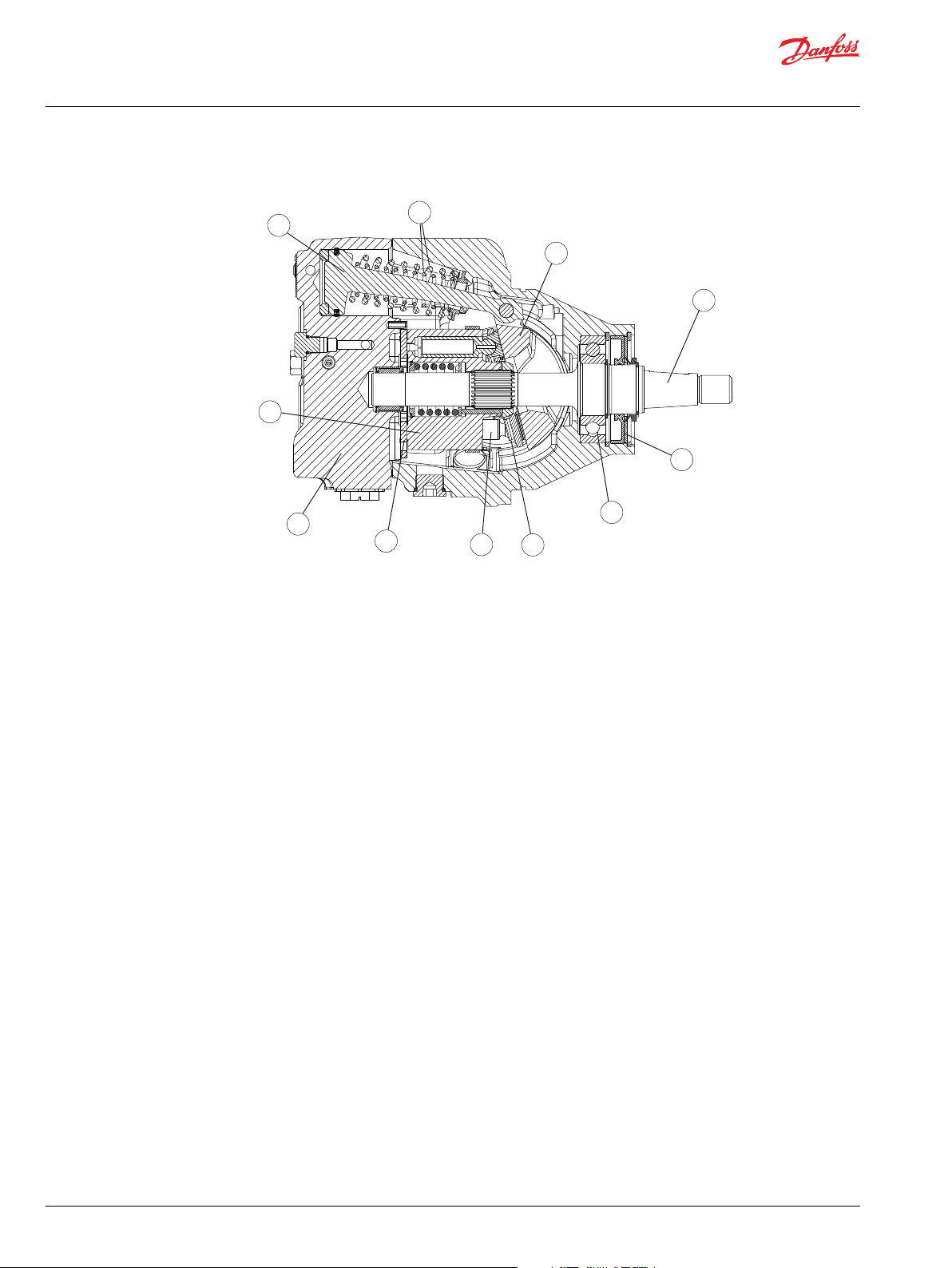
K Frame Cross Section
Key Features
1 Servo piston 7 Slipper
2 Bias springs 8 Piston
3 Swashplate 9 Valve plate
4 Output shaft 10 Endcap
5 Shaft seal 11 Cylinder block
6 Bearing
Designed For Durability and Flexibility
•
Designed for open circuit applications
•
Five displacements allow the optimum selection of a hydraulic motor to fit your application
•
Uses the existing and proven technology of Danfoss L/K motors, for maximum reliability
Installation and Packaging Benefits
•
Short and compact total installed package
•
High Efficiency - nine piston rotating groups with a positive and negative 18 degree maximum angle
•
Uses system pressure for shifting - no external pressure supply needed
•
Integrated shifting valve enables reversing - no external valves needed, which means less hoses, less
losses providing a simple and clean installation
•
12Vdc and 24 Vdc shifting valves
Wide Range of Options
•
Fail Safe: Without control signal, the motor is biased to maximum forward speed
•
Damped shifting
•
Shaft options with dust seal protector
•
Integrated system protection - anti-cavitation and shock valve
•
High capacity bearings to withstand axial fan forces
•
Complimentary to Danfoss Series 45 open circuit pumps with electronic proportional control
•
PLUS+1 micro controller with fan drive software available
•
Variety of porting options allow for easier system configurations
6 | © Danfoss | May 2016 L1427366 | AX00000144en-US0104
P108731
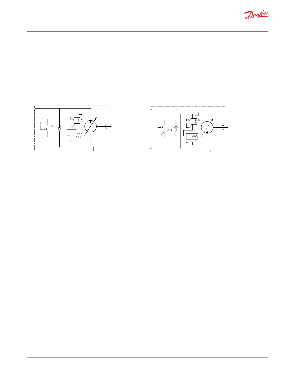
Pressure port A (CW rotation)
Pressure port B (CCW rotation)
Cartridge
A
B
L1
reverse
RDM
Cartridge
A
B
L1
reverse
RDM
Service Manual
Reverse Displacement Motors (RDM), Cartridge Mount
General Information
Metric O-Ring boss
‒
SAE O-Ring boss
‒
Split flange
‒
•
A speed sensor is available
Schematic Diagrams
©
Danfoss | May 2016 L1427366 | AX00000144en-US0104 | 7

Service Manual
Reverse Displacement Motors (RDM), Cartridge Mount
Technical Specifications
Overview
Specifications and operating parameters for RDM motors are given here for quick reference. For
additional information, see Operating Parameters, Features and Options, and Product Coding.
Features and Options
Mount
Motor type
Displacement
Rotation
Installation position
Porting
Output shafts
Control options
Displacement limiter
Dust seal
High capacity bearing
Speed sensor
Anti-Cavitation-Valve
Cartridge
Inline, axial piston, open circuit, reverse displacement motors
L: 25, 30, or 35 cm3 [1.50, 1.83, or 2.14 in3]K: 38 or 45 cm3 [2.32, or 2.75 in3]
Bidirectional
Discretionary: Housing must always be filled with hydraulic fluid
Split flange - SAE O-ring boss, Metric O-ring boss
Tapered, 0.875 in Dia, 1.5 in/ft taper; Straight key, 0.875 in Dia, with dust seal
Integrated shift valve, 12Vdc/24Vdc
Fixed maximum and minimum displacement limiters available
Standard - refer to Features and Options in the RDM Technical Information manual.
Standard - more options available
Available - refer to Features and Options in the RDM Technical Information manual.
Standard - refer to Features and Options in the RDM Technical Information manual.
Specifications
Parameter Unit LM25 LM30 LM35
Displacement (maximum) cm3 [in3] 25 [1.50] 30 [1.83] 35 [2.14] 38 [2.32] 45 [2.75]
Weight (cartridge and SAE-B) kg [lb] 17.5 [38.6]
Mass moment of inertia of rotating components kg•m
Theoretical torque N•m/bar
2
[slug•ft2]
[lbf•in/1000psi]
0.0017
[0.0012]
0.40
[244]
0.0016
[0.0012]
0.48
[293]
0.0015
[0.0011]
0.56
[347]
KM38 KM45
0.0023
[0.0017]
0.60
[366]
0.0023
[0.0017]
0.72
[439]
Operating Parameters
Parameter Unit LM25 LM30 LM35 KM38
System pressure
Output speed
(at max. disp.)
Case pressure limits Rated bar [psi] 0.5 [7] above outlet pressure, 2 [29] maximum pressure
rated/continuous
maximum 350 [5075] 350 [5075] 325 [4715] 350 [5075] 325 [4715]
rated min-1 (rpm) 3400
maximum 3950
Maximum 2 [29] above outlet pressure, 6 [87] maximum pressure
bar [psi]
260 [3770] 260 [3770] 260 [3770] 260 [3770] 260 [3770]
3500 3600
4150 4300
3600 3500
4000 3900
KM45
8 | © Danfoss | May 2016 L1427366 | AX00000144en-US0104

Service Manual
Reverse Displacement Motors (RDM), Cartridge Mount
Technical Specifications
Electrical Parameters
Parameter Unit Value
Voltage Vdc 12, 24
Maximum current recommended (PWM) 12 Vdc mA 1500
24 Vdc 750
Connector - Deutsch Connector DT04-2P
Fluid Specifications
Parameter Unit Minimum Continuous Maximum
Viscosity mm2/sec (cSt) [SUS] 7 [47] 12-60 [70-278] 1600 [7500]
Temperature °C [°F] -40 [-40] 82 [180] 104 [220]
Cleanliness ISO 4406 Class 18/13 or better
Filtration efficiency suction filtration β
Ratings and data are based on operation with premium petroleum-based hydraulic fluids containing
oxidation, rust, and foam inhibitors.
=75 (β10≥1.5)
35-44
©
Danfoss | May 2016 L1427366 | AX00000144en-US0104 | 9

-150
-100
-50
0
50
100
150
0 100 200 300 400 500 600 700 800 900 1000
Displacement (%)
Current (mA)
RDM Control Characteristics
P108736
24Vdc
12Vdc
Cartridge
A
B
L1
reverse
RDM
P108798
Service Manual
Reverse Displacement Motors (RDM), Cartridge Mount
Features
Output shafts
RDM motors may have 22,23mm [0.875 in] 1:8 tapered or straight keyed shafts. Both options have a Dust
Seal. For dimensions, refer to RDM Variable Motors Technical Information, L1424445.
Controls
Reverse Displacement Motors are designed to operate in two positions: maximum forward and maximum
reverse displacement. The motors are spring biased to maximum forward displacement and hydraulically
shifted to reverse.
Reverse Displacement Motors have an integrated shifting valve to go from forward to reverse rotation.
The shifting valve is a proportional pressure reducing valve using system pressure to pilot the servo
piston.
The proportional controllability can be used to achieve a smooth shifting between forward and reverse
rotation. The diagram below shows the motor control characteristics related to valve current (12 Volt
solenoid).
The shaded portion is indicative of the possible variation in shift characteristics. Variation is caused by
differences in system pressure, speed and temperature.
For information regarding Electrical Specifications see Electrical Parameters.
The RDM control has a failsafe design. The integrated shift valve acts like an orifice to dampen the shifting
between maximum forward to maximum reverse and back. This feature protects the system components
against fatal damage in case the control signal changes without ramping or if it gets lost immediately
while reversing.
10 | © Danfoss | May 2016 L1427366 | AX00000144en-US0104
Control orifice, port A high pressure; CW rotation (de-energized shift valve)

Service Manual
Reverse Displacement Motors (RDM), Cartridge Mount
Features
Control current
Supply Voltage (Vdc) Current Range 0-100% [mA]
12 0-1500
24 0-750
©
Danfoss | May 2016 L1427366 | AX00000144en-US0104 | 11

P108844
X1
MA
MB
B
A
F
L1
L1
Service Manual
Reverse Displacement Motors (RDM), Cartridge Mount
Pressure measurements
Required tools
The service procedures described in this manual can be performed using common mechanic's hand
tools. Special tools, if required are shown. Calibrate pressure gauges frequently to ensure accuracy. Use
snubbers to protect gauges.
Port locations and gauge installation
Pressure measurements can be obtained by installing tee fittings to the connections at the locations
listed in the table below. Recommended gauge sizes are listed.
Twin radial port locations
Port information
Port identifier Metric
X1 ISO 6941-1, M 18x1.5
L1 ISO 6941-1, M 14x1.5
A/B ISO 6941-1, M 27x2
MA/MB ISO 11926-1, 7/16 - 20 System gauge port 600 [10,000]
F ISO 11926-1, 7/16-20 Brake release port -
Inch
ISO 11926-1, 3/4-16
ISO 11926-1, 9/16-18
ISO 11926-1, 1-1/16-12
Pressure obtained Gauge size, bar [psi]
Control signal 600 [10 000]
Case drain 10 [100]
System pressure 600 [10 000]
12 | © Danfoss | May 2016 L1427366 | AX00000144en-US0104

W
Service Manual
Reverse Displacement Motors (RDM), Cartridge Mount
Initial start-up procedures
General
Follow this procedure when starting-up a new motor installation or when restarting an installation in
which the motor has been removed.
Warning
Unintended vehicle or machine movement hazard
When using the RDM in combination with S45 open circuit pumps with LS or EPC be aware that there will
likely be motor movement as long as the engine is turning. Due to the LS-setting of the pump, a standby
pressure will remain in the system even if the normally closed control is fully energized. Lowest standby
pressures to the motor, 15-18 bar or above, may be enough to turn the RDM and has the potential to
cause injury or damage.
Prior to installing the motor, inspect for damage incurred during shipping. Make certain all system
components (reservoir, hoses, valves, fittings, heat exchanger, etc.) are clean prior to filling with fluid.
Startup-procedure
1. Fill the reservoir with recommended hydraulic fluid. Always filter fluid through a 10 micron filter
when pouring into the reservoir. Never reuse hydraulic fluid.
2. Fill the inlet line leading from the pump to the reservoir. Check the inlet line for properly tightened
fittings and be certain it is free of restrictions and air leaks.
3. Fill the pump and motor housing with clean hydraulic fluid. Pour filtered oil directly into the case
drain port.
4. To ensure the pump and motor stay filled with oil, install case drain lines into the case drain port.
5. When using Series 45 pump, install a gauge at port M1 to monitor system pressure during start up.
Alternatively use a tee fitting to install a gauge at the high pressure motor port (A or B).
Follow recommendations in the vehicle / machine operator's manual for prime mover start up
procedures.
6. While watching the pressure gauge, jog the prime mover or run at the lowest possible speed until
system pressure builds to normal levels (minimum 11 bar [160 psi]). Once system pressure is
established, increase to full operating speed. If system pressure is not maintained, shut down the
prime mover, determine cause, and take corrective action. Refer to Troubleshooting on page 15.
7. Operate the hydraulic system for at least fifteen minutes under light load conditions.
8. Check and adjust pump control settings as necessary after installation.
9. Shut down the prime mover and remove the pressure gauge. Replace plug at the gauge port (remove
tee fitting).
10. Check the fluid level in the reservoir; add clean filtered fluid if necessary.
The motor is now ready for operation.
©
Danfoss | May 2016 L1427366 | AX00000144en-US0104 | 13

Service Manual
Reverse Displacement Motors (RDM), Cartridge Mount
Fluid and filter maintenance
Recommendations
To ensure optimum life of these motors, perform regular maintenance of the fluid and filter.
Contaminated fluid is the main cause of unit failure. Take care to maintain fluid cleanliness when
servicing.
Check the reservoir daily for proper fluid level, the presence of water, and rancid fluid odor. Fluid
contaminated by water may appear cloudy or milky or free water may settle in the bottom of the
reservoir. Rancid odor indicates the fluid has been exposed to excessive heat. Change the fluid
immediately if these conditions occur. Correct the problem immediately.
Change the fluid and filter per the vehicle / machine manufacturer's recommendations or at these
intervals:
Fluid and filter change interval
Reservoir type Max oil change interval
Sealed 2000 hours
Breather 500 hours
Change the fluid more frequently if it becomes contaminated with foreign matter (dirt, water, grease,
etc.) or if the fluid is subjected to temperature levels greater that the recommended maximum.
Dispose of used hydraulic fluid properly. Never reuse hydraulic fluid.
Change filters whenever the fluid is changed or when the filter indicator shows that it is necessary to
change the filter. Replace all fluid lost during filter change.
14 | © Danfoss | May 2016 L1427366 | AX00000144en-US0104

Service Manual
Reverse Displacement Motors (RDM), Cartridge Mount
Troubleshooting
Excessive noise and/or vibration
Item Description Action
Check oil level in reservoir
and oil supply to the motor.
Check for air in the system. Air trapped within the system lines, or the motor itself,
Inspect the output shaft
couplings.
Inspect the output shaft
alignment.
Hydraulic oil viscosity above
limits.
System operating hot
Item Description Action
Check oil level in reservoir
and oil supply to the pump.
Inspect the heat exchanger,
(if so equipped).
Check the system relief
valves.
Insufficient hydraulic fluid could lead to cavitation that
would cause system noise.
could result in cavitation that would cause system noise.
A loose or incorrect shaft coupling will produce vibrations
that could result in system noise.
Misaligned shafts create excessive frictional vibration that
could result in system noise.
Viscosity above acceptable limits will result in cavitation
that would lead to system noise.
Insufficient amount of hydraulic fluid will not meet the
cooling demands of the system.
If the heat exchanger fails, or becomes obstructed, it may
not meet the cooling demands of the system.
If a system relief valve becomes unseated for an extended
period of time or fails for any other reason, the system
could become overheated.
Fill the reservoir to the proper level and ensure that oil
supply to the motor is adequate and the lines are
unobstructed.
Ensure that all of the system lines and components are
purged of air.
Ensure that the correct coupling is used and that it fits
properly onto the shaft.
Ensure that the shafts are properly aligned.
Replace hydraulic oil with appropriate fluid for operating
conditions. Refer to publication 5200L0463 for information
on fluid selection.
Fill the reservoir to the proper level.
Ensure that heat exchanger is receiving adequate air flow
and that the heat exchanger is in good operating
condition. Repair or replace as necessary.
Repair or replace any malfunctioning relief valves as
applicable and verify that the loads on the machine are not
excessive.
Motor shifting irregularities
Item Description Action
Check the electrical
connection and electrical
signal to the shifting valve
coil.
Check valve coil The energized valve coil is moving the valve spool. That
Check shifting pressure. Shifting pressure moves servo piston. Obstruction could
Electrical signal is needed to energize the valve coil. The
energized coil is shifting the motor.
leads to motor shifting.
result in slow or no shift conditions.
Ensure that the electrical connection between controller
valve coil is alright. Check wires and connectors. Check
electric signal. Valve coil can be energized with 12V PWMsignal or directly with 12V.
Measure valve coil resistance. Value needs to be 5,3ohms
+-5%. Replace valve if resistance is differing.
Shifting pressure at full energized valve coil (1500mA)
needs to be at 20-32bar [290-464psi] or system input
pressure, whichever is lower. Replace shifting valve when
measured pressure is differing.
©
Danfoss | May 2016 L1427366 | AX00000144en-US0104 | 15

B005
M004
M003
P108740
D007
D006
Service Manual
Reverse Displacement Motors (RDM), Cartridge Mount
Minor repair
Shaft seal replacement
Remove the shaft seal
1. Remove the snap ring (D007).
2. Remove dust seal (D006).
3. Remove the snap ring (B005) retaining the shaft seal and support washer.
4. Remove the support washer (M004).
5. Carefully pry out the shaft seal (M003).
To avoid damaging the shaft during removal, install a large sheet metal screw into the chuck of a slide
hammer. Drive the screw into the seal surface and use the slide hammer to pull the seal.
6. Discard the seals (D006 and M003).
Inspect the components
Inspect the motor housing seal bore, and the sealing area on the shaft for rust, wear, and
contamination. Polish the shaft and clean the housing if necessary.
Install the new shaft seal
1. Cover the shaft with an installation sleeve to protect the shaft and seals during installation.
2. Install a new shaft seal (M003) with the cupped side facing the motor. Press seal into housing until it
bottoms out. Press evenly to avoid binding and damaging the seal.
3. Install seal support washer (M004).
4. Install snap ring (B005).
5. Install the dust seal (D006).
6. Install snap ring (D007) to lock the dust seal.
7. Remove the installation sleeve.
16 | © Danfoss | May 2016 L1427366 | AX00000144en-US0104

QE080
E080
E081
P108741-
Service Manual
Reverse Displacement Motors (RDM), Cartridge Mount
Minor repair
Shifting Valve
Remove shifting valve
1. Using a 3mm internal hex wrench, remove screws (E081).
2. Remove valve (E080).
3. Remove and discard O-rings (QE080).
Anti-Cavitation Valve
Item Wrench size Torque
E081 3 mm 8 Nm [6 lbf-ft]
Inspect the components
Inspect sealing area for rust, wear, or contamination.
Install shifting valve
1. Lubricate and install new O-rings (QE080).
2. Insert valve (E080) into valve seat.
3. Using a 3mm internal hex wrench, install screws (E081). Torque to 2.5 Nm [2 lb•ft].
Remove the anti-cavitation valve
The anti-cavitation valve is installed into the high pressure port. The high pressure port depends on
motor rotation. If forward rotation is counterclockwise, the high pressure port is A. If forward rotation is
clockwise, the high pressure port is B.
1. Using a 5/16 in internal hex wrench remove valve plug (E061). Remove and discard O-ring (E063).
2. Remove spring (E012) and relief valve (E011) from end cap.
3. Using a 5/16 in internal hex wrench remove plug (E020).
©
Danfoss | May 2016 L1427366 | AX00000144en-US0104 | 17
Standard plugs, with O-rings installed, are included in the overhaul seal kit.

E020
E061
E012
E063
E011
P108742
Service Manual
Reverse Displacement Motors (RDM), Cartridge Mount
Minor repair
Anti-cavitation valve
Item Wrench size Torque
E061 5/16 inch 80 Nm [59 lbf-ft]
E020 5/16 inch 80 Nm [59 lbf-ft]
Inspect the components
Inspect sealing area for rust, wear, or contamination. Check spring and relief valve for wear and
damage. Relief valve is non-serviceable, replace as complete unit if damaged.
Install the anti-cavitation valve
1. Lubricate and insert relief valve (E011) and spring (E012) in original location.
2. Lubricate and install new O-ring (E063) on valve plug (E061).
3. Lubricate O-ring on plug (E020).
4. Using a 5/16 inch internal hex wrench to install valve plug (E061) into the port with a relief valve.
Torque to 80 N•m [59 lbf•ft].
5. Using a 5/16 inch internal hex wrench, install plug (E020) into the port without a relief valve. Torque
to 80 N•m [59 lbf•ft].
Speed Sensor installation and adjustment
1. Loosen locknut (K011).
Keep all of the old parts until you receive and inventory new parts.
18 | © Danfoss | May 2016 L1427366 | AX00000144en-US0104

0002
K010
K011A
K011
P108807
Air gap to be 1.52 [0.060] max.
(Approx. 1/2-1 turn of thread)
M12x1D6G thread
Keyway ref.
Pin 2
direction
Pin 1
power +
Pin 3
speed
12.7 [0.50]
flats
Pin 4
ground
Speed
ring
61.2
[2.41]
50.8
[2.00]
16.2
[0.64]
P108806
Shaft
centerline
1/2 inch
wrench flats
Shaft
centerline
1/2 inch
wrench flats
22°
22°
22°
22°
P101332Erev
Service Manual
Reverse Displacement Motors (RDM), Cartridge Mount
Minor repair
Speed sensor installation
2. Push the O-ring (K011A) upward, toward the connector end of the sensor unit so that the O-ring does
not contact the motor housing during step 3.
3. Thread the sensor (CW) into the motor housing by hand until the bottom end touches the speed ring.
4. Back the sensor out (CCW) 1/2 turn.
©
Danfoss | May 2016 L1427366 | AX00000144en-US0104 | 19

Service Manual
Reverse Displacement Motors (RDM), Cartridge Mount
Minor repair
5. Continue backing the sensor out until the flats are 22° either side of the motor shaft center line as
shown in the above illustration (20° to 30° is acceptable).
6. Hold the sensor in place with a 1/2 inch wrench. Using an 11/16 inch wrench, torque the locknut
(K011) to 13 Nm [10 lbf•ft].
20 | © Danfoss | May 2016 L1427366 | AX00000144en-US0104

Service Manual
Reverse Displacement Motors (RDM), Cartridge Mount
©
Danfoss | May 2016 L1427366 | AX00000144en-US0104 | 21

Service Manual
Reverse Displacement Motors (RDM), Cartridge Mount
22 | © Danfoss | May 2016 L1427366 | AX00000144en-US0104

Service Manual
Reverse Displacement Motors (RDM), Cartridge Mount
©
Danfoss | May 2016 L1427366 | AX00000144en-US0104 | 23

Danfoss
Power Solutions GmbH & Co. OHG
Krokamp 35
D-24539 Neumünster, Germany
Phone: +49 4321 871 0
Danfoss
Power Solutions ApS
Nordborgvej 81
DK-6430 Nordborg, Denmark
Phone: +45 7488 2222
Danfoss
Power Solutions (US) Company
2800 East 13th Street
Ames, IA 50010, USA
Phone: +1 515 239 6000
Danfoss
Power Solutions Trading
(Shanghai) Co., Ltd.
Building #22, No. 1000 Jin Hai Rd
Jin Qiao, Pudong New District
Shanghai, China 201206
Phone: +86 21 3418 5200
Products we offer:
Comatrol
www.comatrol.com
Schwarzmüller-Inverter
www.schwarzmuellerinverter.com
Turolla
www.turollaocg.com
Hydro-Gear
www.hydro-gear.com
Daikin-Sauer-Danfoss
www.daikin-sauer-danfoss.com
Bent Axis Motors
•
Closed Circuit Axial Piston
•
Pumps and Motors
Displays
•
Electrohydraulic Power
•
Steering
Electrohydraulics
•
Hydraulic Power Steering
•
Integrated Systems
•
Joysticks and Control
•
Handles
Microcontrollers and
•
Software
Open Circuit Axial Piston
•
Pumps
Orbital Motors
•
PLUS+1® GUIDE
•
Proportional Valves
•
Sensors
•
Steering
•
Transit Mixer Drives
•
Danfoss Power Solutions is a global manufacturer and supplier of high-quality hydraulic and
electronic components. We specialize in providing state-of-the-art technology and solutions
that excel in the harsh operating conditions of the mobile off-highway market. Building on
our extensive applications expertise, we work closely with our customers to ensure
exceptional performance for a broad range of off-highway vehicles.
We help OEMs around the world speed up system development, reduce costs and bring
vehicles to market faster.
Danfoss – Your Strongest Partner in Mobile Hydraulics.
Go to www.powersolutions.danfoss.com for further product information.
Wherever off-highway vehicles are at work, so is Danfoss. We offer expert worldwide support
for our customers, ensuring the best possible solutions for outstanding performance. And
with an extensive network of Global Service Partners, we also provide comprehensive global
service for all of our components.
Please contact the Danfoss Power Solution representative nearest you.
Local address:
Danfoss can accept no responsibility for possible errors in catalogues, brochures and other printed material. Danfoss reserves the right to alter its products without notice. This also applies to products
already on order provided that such alterations can be made without changes being necessary in specifications already agreed.
All trademarks in this material are property of the respective companies. Danfoss and the Danfoss logotype are trademarks of Danfoss A/S. All rights reserved.
©
Danfoss | May 2016 L1427366 | AX00000144en-US0104
 Loading...