

Page 1
MAKING MODERN LIVING POSSIBLE
Data sheet
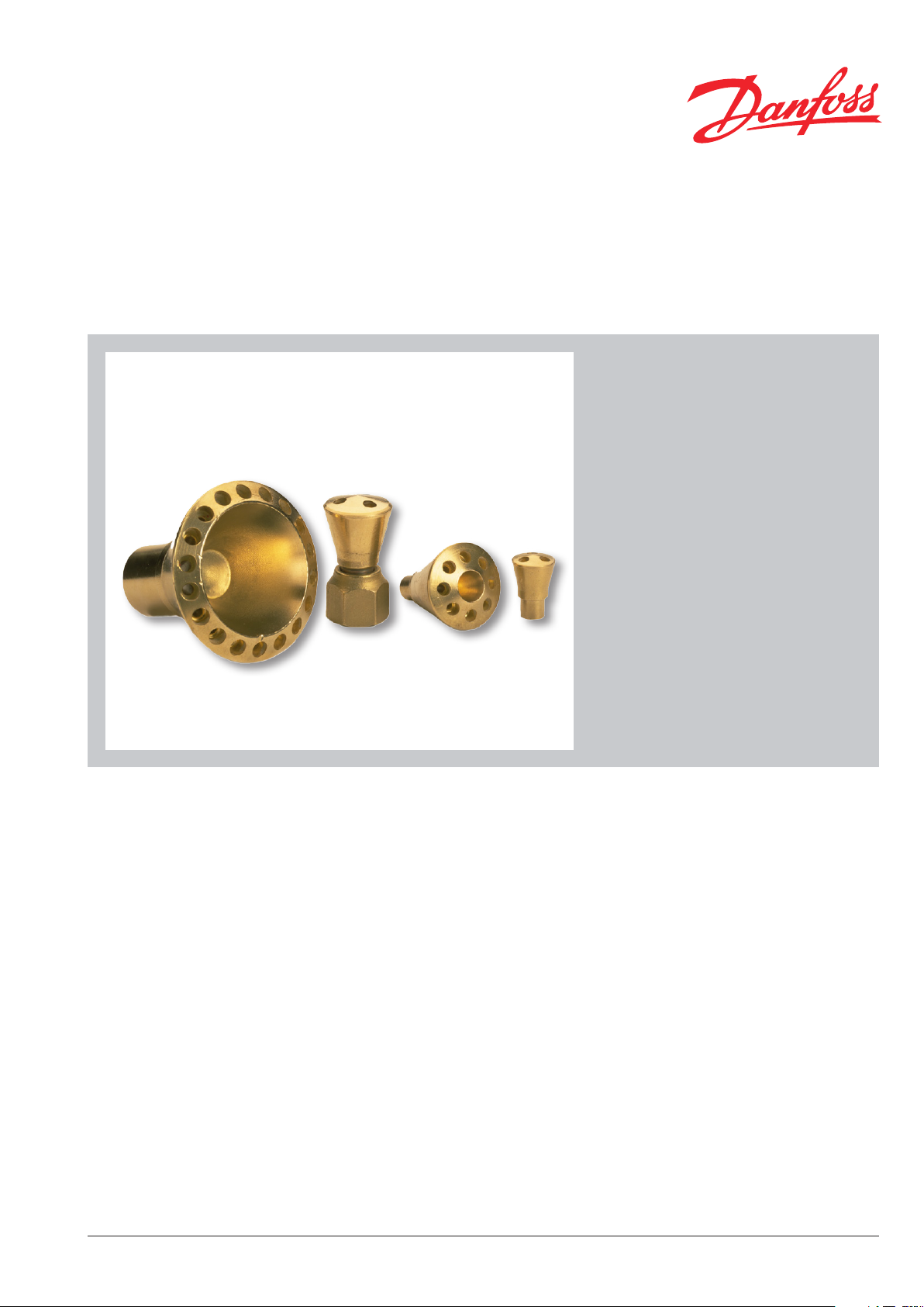
Liquid Distributor
Type RD
The RD refrigerant distributors distribute
liquid refrigerants from the thermostatic
expansion valve to individual sections of the
evaporator.
Note!
The thermostatic expansion valve must have
external pressure equalization.
Features y A wide range of RD refrigerant distributors is
available, covering the majority of customer
demands.
y RD design ensures a uniform distribution of
refrigerant to each evaporator section.
y Suitable for refrigerants R22, R134a,
R404A, R407C, R507, R410A.
Concerning other refrigerants
please contact Danfoss.
y Maximum working pressure:
MWP/PS 48 bar/700 psig.
DKRCC.PD.FF0.A2.02 / 520H7413
Page 2
Data sheet Liquid Distributor, type RD
R64-2102.10
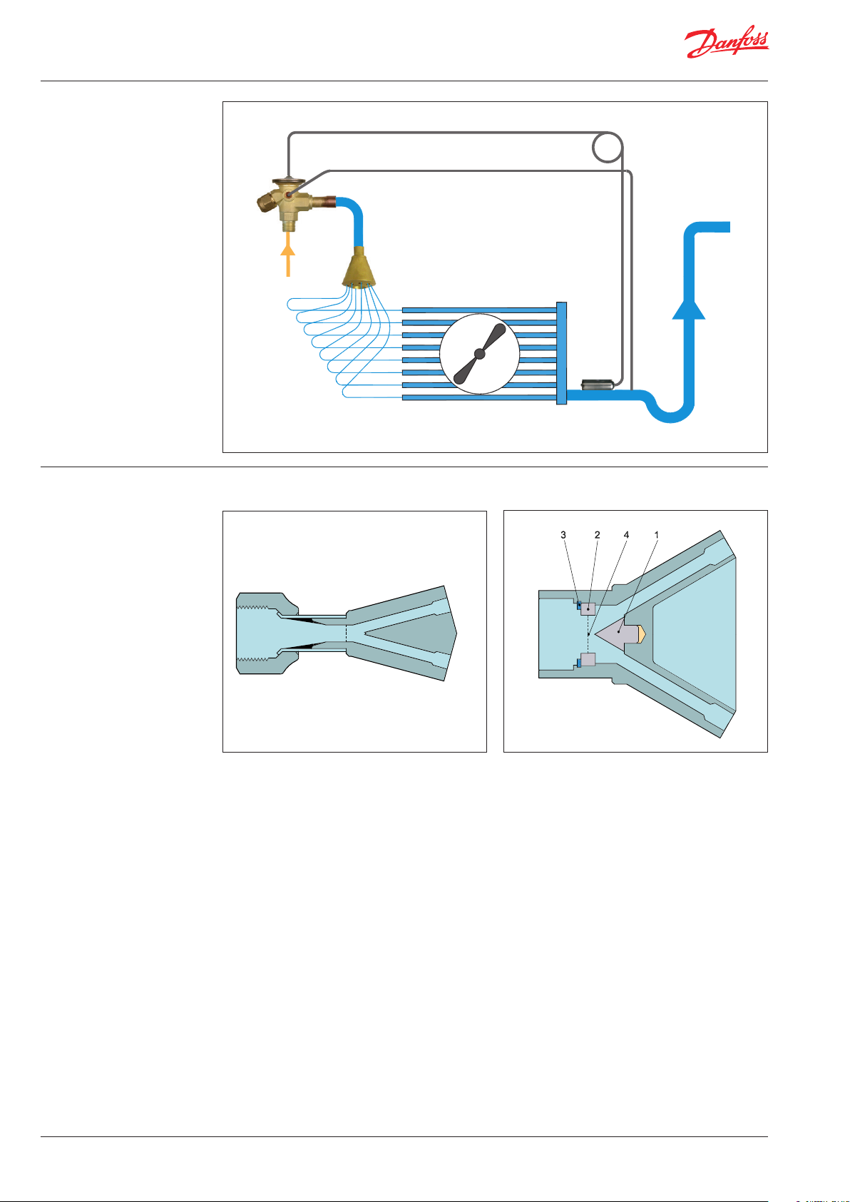
Application example
Danfoss
Design RD, are RD, solder ODM
Danfoss
69G184.12.12
Danfoss
69G183.12
1. Cone
2. Nozzle
3. Locking ring
4. Nozzle diameter
2 DKRCC.PD.FF0.A2.02 / 520H7413
Page 3
Data sheet Liquid Distributor, type RD
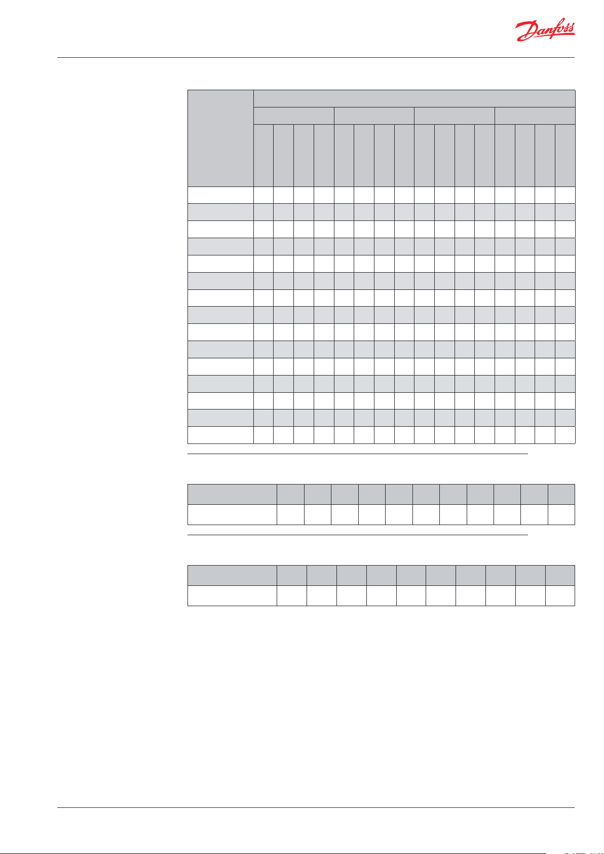
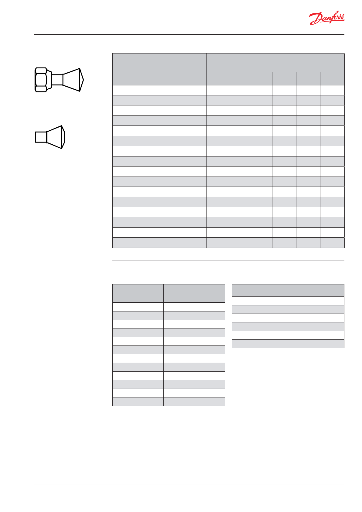
Capacity Table 1. Capacity in kW for 1 m distributor tube with ∆p = 0.5 bar
Outer diameter of distributor tubes
3
Evaporating
/16 in. / 5 mm
temperature
t
e
[°C]
R22 / R407C
R134a
R404A / R507
10 2.4 2.1 1.9 2.6 5.1 4.2 3.8 5.6 9.7 8 7.2 10.7 15.8 13.1 12 17.4
5 2.2 1.8 1.6 2.4 4.5 3.7 3.4 5.0 8.5 7 6.4 9.4 14 11.6 10.6 15.4
0 1.9 1.6 1.5 2.1 4 3.3 3 4.4 7.4 6.1 5.6 8.1 12.3 10.1 9.3 13.5
-5 1.6 1.3 1.3 1.8 3.4 2.8 2.6 3.7 6.4 5.3 4.6 7.0 10.6 8.7 8 11.7
-10 1.4 1.2 1.1 1.5 2.9 2.4 2.2 3.2 5.5 4.5 4.2 6.1 9.1 7.4 6.9 10
-15 1.2 0.99 0.93 1.3 2.4 2 1.9 2.6 4.7 3.8 3.5 5.2 7.7 6.3 5.8 8.5
-20 0.99 0.87 0.76 1.1 2.1 1.7 1.6 2.3 4 3.3 3 4.4 6.5 5.4 5 7.2
-25 0.87 0.7 0.64 0.96 1.7 1.5 1.3 1.9 3.3 2.7 2.5 3.6 5.6 4.5 4.2 6.2
-30 0.7 0.58 0.52 0.77 1.5 1.2 1.1 1.7 2.8 2.3 2.1 3.1 4.7 3.8 3.5 5.2
-35 0.58 0.47 0.47 0.64 1.2 0.99 0.93 1.3 2.3 1.9 1.7 2.5 3.9 3.1 2.9 4.3
-40 0.52 0.41 0.41 0.57 1.1 0.87 0.81 1.2 2 1.7 1.5 2.2 3.3 2.7 2.5 3.6
-45 0.47 0.35 0.35 0.52 0.87 0.76 0.7 0.96 1.7 1.4 1.3 1.9 2.8 2.3 2.2 3.1
-50 0.41 0.29 0.29 0.45 0.76 0.64 0.6 0.84 1.5 1.2 1.1 1.7 2.4 2 1.9 2.6
-55 0.35 0.23 0.23 0.39 0.64 0.52 0.52 0.70 1.3 1 0.93 1.4 2.2 1.7 1.6 2.4
-60 0.29 0.2 0.18 0.32 0.52 0.47 0.47 0.57 1.2 0.81 0.76 1.3 1.9 1.4 1.5 2.1
R410A
1
/4 in. / 6 mm
R22 / R407C
R134a
R404A / R507
R410A
5
/16 in. / 8 mm
R22 / R407C
R134a
R404A / R507
R410A
3
/8 in. / 10 mm
R22 / R407C
R134a
R404A / R507
R410A
Table 2. Correction factor for tube length
Tube length [mm] 250 400 550 700 850 1000 1150 1300 1450 1600 1750
Correction Factor 1.55 1.29 1.19 1.11 1.05 1.00 0.95 0.90 0.87 0.84 0.78
Table 3. Correction factor for liquid temperature
Liquid temperature [°C] 10 15 20 25 28 30 35 40 45 50
Correction factor 1.59 1.40 1.24 1.09 1.00 0.95 0.82 0.71 0.61 0.52
DKRCC.PD.FF0.A2.02 / 520H7413 3
Page 4
Data sheet Liquid Distributor, type RD
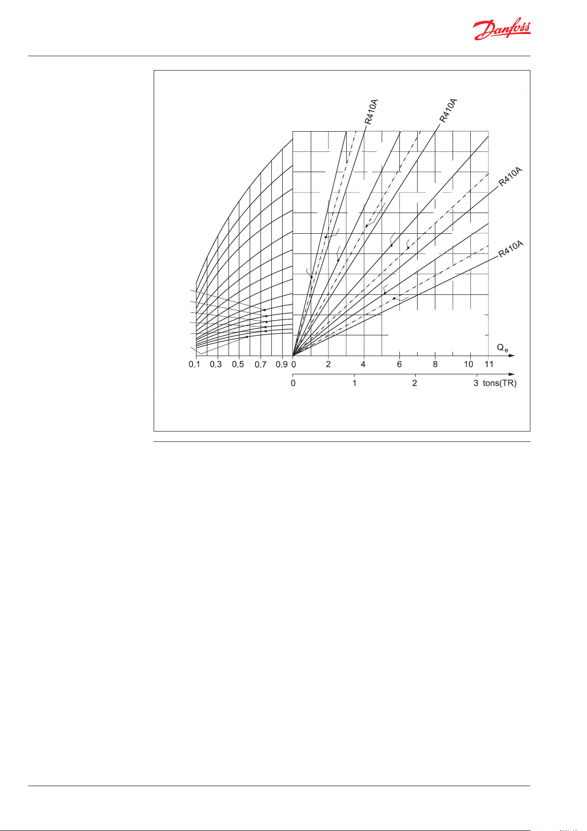
Capacity
(continued)
Danfoss
A69-141.11_FW
= 10 °C
e
t
5 °C
0 °C
1/4 in. / 6 mm
R22
-5 °C
-10 °C
-35 °C
-40 °C
-15 °C
-20 °C
-25 °C
-30 °C
R134a, R404A 3/16 in. / 5 mm
-45 °C
-50 °C
-55 °C
-60 °C
Δp [bar]
Figure 1
It is recommended that distributor tubes are
sized for a pressure drop of approx. 0.5 bar.
Table 1, which gives the capacities for dierent
tube sizes, is based on this pressure drop.
R22 3/16 in. / 5 mm
R134a, R404A 5/16 in. / 8 mm
R22 5/16 in. / 8 mm
R134a, R404A 1/4 in. / 6 mm
R134a, R404A 3/8 in. / 10 mm
R22 3/8 in. / 10 mm
3
/
in.: ø4.80 × 3.00 mm
16
1
/
in.: ø6.35 × 4.80 mm
4
5
/
in.: ø7.94 × 6.16 mm
16
3
/
in.: ø9.53 × 7.75 mm
8
[kW]
Figure 1 shows the relation between evaporator
capacity Qe, refrigerant, tube diameter, evaporating
temperature t
and pressure drop Δp for 1 m
e
distributor tube.
For tube lengths exceeding 1 m, tubes should be
selected with larger diameters than indicated in
table 1.
4 DKRCC.PD.FF0.A2.02 / 520H7413
Page 5
Data sheet Liquid Distributor, type RD
Ordering
RD, are
RD, solder
Table 4
Distributor
type
RD 21
RD 27
RD 21
RD 27
RD 33
RD 33
RD 42
RD 33
RD 33
RD 42
RD 49
RD 49
RD 62
1)
RD 79
1)
RD 85
1)
RD 85
1)
Replaceable nozzle, for nozzles with other diameters, see table 5
Distributor inlet
1
/2 in. are ≤ 25 kW (7 TR) 4 3 — —
1
/2 in. are ≤ 25 kW (7 TR) 6 5 — —
1
/2 in. / 12 mm solder ODM ≤ 25 kW (7 TR) 4 3 — —
1
/2 in. / 12 mm solder ODM ≤ 25 kW (7 TR) 6 5 — —
1
/2 in. are ≤ 35 kW (10 TR) 9 6 — —
1
/2 in. / 12 mm solder ODM ≤ 35 kW (10 TR) 9 6 — —
1
/2 in. / 12 mm solder ODM ≤ 35 kW (10 TR) 13 9 — —
5
/8 in. are ≤ 35 kW (10 TR) 8 6 4 —
5
/8 in. / 16 mm solder ODM ≤ 35 kW (10 TR) 8 6 4 —
5
/8 in. / 16 mm solder ODM ≤ 35 kW (10 TR) 13 9 7 —
5
/8 in. / 16 mm solder ODM ≤ 85 kW (25 TR) 17 14 10 —
7
/8 in. / 22 mm solder ODM ≤ 85 kW (25 TR) 17 14 10 —
7
/8 in. / 22 mm solder ODM ≤ 120 kW (35 TR) — 18 14 —
11/8 in. / 28 mm solder ODM ≤ 250 kW (70 TR) — 24 19 15
11/8 in. / 28 mm solder ODM ≤ 300 kW (85 TR) — 27 22 18
13/8 in. / 35 mm solder ODM ≤ 300 kW (85 TR) — 27 22 18
Rated capacity of
expansion valves
(R407C)
Max. number of holes and size of distributor
outlet (ODF)
3
/16 in. /
5 mm
1
/4 in. /
6 mm
5
/16 in. /
8 mm
3
/8 in. /
10 mm
Table 5. Standard nozzle size Table 6. Rated capacity correction factor depending
on refrigerant (for use in conjunction with table 4)
Distributor type Nozzle diameter 1) [mm]
RD 21 5.0
RD 27 5.0
RD 33 6.0
RD 42 6.0
RD 49 8.0
RD 62 9.0
RD 79 8.0
RD 79 10.1
RD 79 12.4
RD 79 14.3
RD 85 17.5
RD 85 18.5
1)
The optimum nozzle diameter depends on the plant conditions.
Refrigerant Correction factor
R407C 1.00
R22 0.92
R134a 0.72
R507 0.68
R404A 0.68
R410A 1.14
DKRCC.PD.FF0.A2.02 / 520H7413 5
Page 6
Data sheet Liquid Distributor, type RD
Type nomenclature
Table 7
Type RD Refrigerant Distributor
21 ø21 mm
27 ø27 mm
33 ø33 mm
Body
Inlet connector
42 ø42 mm
49 ø49 mm
79 ø79 mm
85 ø85 mm
A 12 mm solder ODM
B 16 mm solder ODM
C 22 mm solder ODM
D 28 mm solder ODM
E 35 mm solder ODM
1
J
L 1
/2 in. solder ODM
5
/8 in. solder ODM
7
/8 in. solder ODM
1
/8 in. solder ODM
3
/8 in. solder ODM
1
/2 in. are F
5
/8 in. are F
H
K
M 1
P
Q
Nozzle size ## mm
A 5 mm solder ODF
B 6 mm solder ODF
C 8 mm solder ODF
D 10 mm solder ODF
Outlet connector
3
J
L
/16 in. solder ODF
1
/4 in. solder ODF
5
/16 in. solder ODF
3
/8 in. solder ODF
H
K
Number of holes ## 2 – 27
Example of a type code:
RD 21 — H 05 — J 03
Body
Nozzle size
Inlet connector
Refrigerant distributor
Number of holes
Outlet connector
6 DKRCC.PD.FF0.A2.02 / 520H7413
Page 7

Data sheet Liquid Distributor, type RD
Selection of refrigerant
distributor
The following data must be known:
1. Refrigerant
2. Evaporator capacity
3. Evaporating temperature
4. Liquid temperature
5. Number of evaporator sections
6. Evaporator section inlet size
7. Distributor tube length
8. Expansion valve type
It is then possible to determine:
I. Size of distributor tubes
Example
Given data:
1. Refrigerant: R404A
2. Evaporator capacity Q
3. Evaporating temperature t
4. Liquid temperature T
: 20 kW
e
: 20 °C
l
: -15 °C
e
5. Number of evaporator sections: 10
6. Evaporator section inlet size: 6 mm
7. Distributor tube length: 850 mm
8. Expansion valve with 22 mm ODF solder
connection on outlet side
The capacity of the individual distributor tube is
calculated by dividing the total evaporator capacity
by the number of uniform evaporator sections.
The tube diameter can then be determined from
table 1 or gure 1.
Sizing should be based on the average capacity
of the evaporator.
A suciently uniform distribution can be expected
at capacities of between 40% and 125% of the values
given in table 1.
The capacity of each individual distributor tube is
20 / 10=2.0 kW.
Table 1 shows that with an evaporating temperature
of -15 °C and R404A, a ø6 mm tube with a length
of 1 meter will yield 1.9 kW.
Correction factors for tube length and liquid
temperature are found in tables 2 and 3.
For a tube length of 850 mm, the correction
factor is 1.05. For a liquid temperature of 20 °C,
the correction factor is 1.24.
Under the given conditions, the distributor tubes
yield 1.9×1.24×1.05=2.47 kW.
The actual load, as a percentage of the listed rating,
is thus 2.0 / 2.47=0.81 or 81%.
The type of distributor, inlet size and type are
determined from table 4.
There are two options: RD 49 or RD 62.
The rated capacity of the expansion valve can be
found using table 6 together with table 4:
– RD 49: 85×0.68=58 kW
– RD 62: 120×0.68=82 kW
Both distributors can be used, but RD 49 is
selected because the rated capacity is closer to
the evaporator capacity.
The standard nozzle diameter is determined from
table 5: 8 mm.
The required distributor type is determined from
table 7: RD49-C08-B10.
Please contact Danfoss for the code number.
DKRCC.PD.FF0.A2.02 / 520H7413 7
Page 8

Data sheet Liquid Distributor, type RD
Dimensions [mm]
and weights [kg]
RD, are RD, solder ODM
Table 8
Distributor
type
Distributor inlet L L
1
D
RD 21 Flare 55 — 21 0.1 24
RD 21 Solder 31 10 21 0.1 24
Approx. net
weight
Industrial
pack
RD 27 Flare 65 10 27 0.1 24
RD 27 Solder 41 10 27 0.1 24
RD 33 Flare (
RD 33 Solder (
RD 33 Flare (
RD 33 Solder (
1
⁄2 in.) 71 — 33 0.2 24
1
⁄2 in. / 12 mm) 50 12 33 0.2 24
5
⁄8 in.) 76 — 33 0.2 24
5
⁄8 in. / 16 mm) 50 17 33 0.2 24
RD 42 Solder 52 12 42 0.2 15
5
RD 49 Solder (
RD 49 Solder (
⁄8 in. / 16 mm) 62 17 49 0.3 15
7
⁄8 in. / 22 mm) 62 24 49 0.3 15
RD 62 Solder 66 24 62 0.7 9
RD 79 Solder 81 25 79 0.9 6
RD 85 Solder 81 30 85 0.9 6
8 DKRCC.PD.FF0.A2.02 / 520H7413
© Danfoss A/S (AC-MCI / jmn), 2013-03
 Loading...