

Page 1
Data Sheet
Fixed Capacity ValvesType RA-FN (Series F)
Application
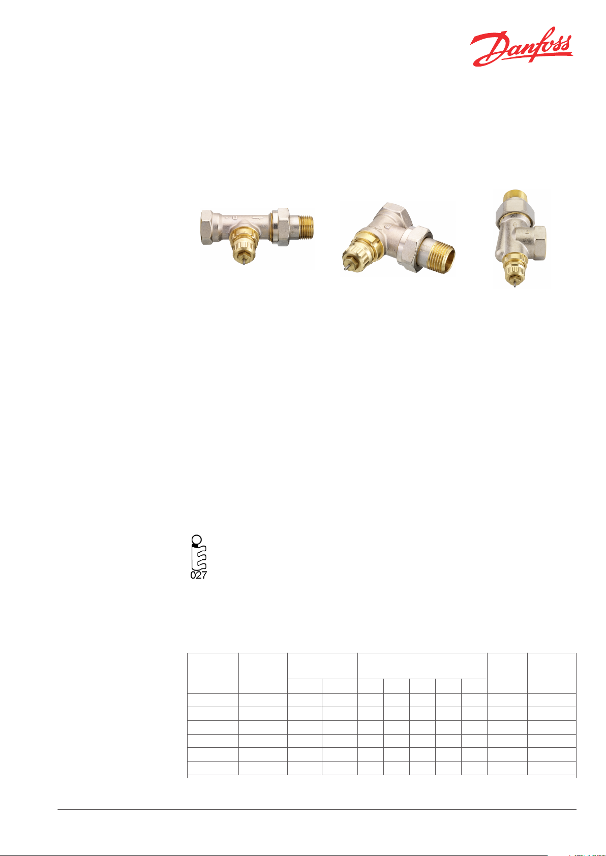
RA-FN straight RA-FN angle RA-FN horizontal angle
Approved to EN 215
The RA-FN valve bodies are used in two-pipe
heating systems.
The valves are manufactured from brass with
nickel plating. The pressure pin of the gland seal
is of chromium steel and works in a lifetime
lubricated O-ring seal. The complete gland
assembly can be replaced without draining down
the system.
The valves are supplied with a grey protective
cap, which can be used for manual regulation
during the construction phase. The protective
cap must not be used as a manual shut off
device. A special manual shut off device (code no.
013G3300) should be used.
All Danfoss RA-FN fixed capacity valves,
series F, are certified according to the
European Standard EN 215.
Compression fittings for 15 mm, 10 mm or 8 mm
copper tube are available for RA-FN with 3/8” and
1/2” connections.
In order to avoid deposition and corrosion, the
composition of the hot water must be in
accordance with the VDI 2035 guideline (Verein
Deutscher Ingenieure).
It is recommended that formulations containing
mineral oil are avoided.
All RA-FN valve bodies can be used together with
all types of thermostatic elements in the Danfoss
RA2000 series.
Code Nos. and Technical
Data
Danfoss Heating Solutions VDSXI202 © Danfoss 12/2010 1
Valve bodies for two-pipe systems type RA-FN
(series F)
1)
Type Design
RA-FN 10 angle Rp 3/8 R 3/8 0.17 0.34 0.47 0.56 0.65 120 °C 013G0001
RA-FN 10 straight Rp 3/8 R 3/8 0.17 0.34 0.47 0.56 0.65 120 °C 013G0002
RA-FN 10 horizontal Rp 3/8 R 3/8 0.17 0.34 0.47 0.56 0.65 120 °C 013G0141
RA-FN 15 angle Rp 1/2 R 1/2 0.22 0.43 0.57 0.73 0.90 120 °C 013G0003
RA-FN 15 straight Rp 1/2 R 1/2 0.22 0.43 0.57 0.73 0.90 120 °C 013G0004
RA-FN 15 horizontal Rp 1/2 R 1/2 0.22 0.43 0.57 0.73 0.90 120 °C 013G0143
Connections
Inlet Outlet 0.5K 1.0K 1.5K 2.0K
kv-value
pressure drop), P-band = K
(m3/h at 1 bar
k
vs
Max.
working
temp.
Code no.
Page 2

Data Sheet Fixed Capacity ValvesType RA-FN (Series F)
RA-FN 20 angle Rp 3/4 R 3/4 0.30 0.58 0.83 1.04 1.40 120 °C 013G0005
RA-FN 20 straight Rp 3/4 R 3/4 0.30 0.58 0.83 1.04 1.40 120 °C 013G0006
RA-FN 20 horizontal Rp 3/4 R 3/4 0.25 0.50 0.67 0.80 1.00 120 °C 013G0145
RA-FN 25 angle Rp 1 R 1 0.30 0.58 0.83 1.04 1.40 120 °C 013G0027
RA-FN 25 straight Rp 1 R 1 0.30 0.58 0.83 1.04 1.40 120 °C 013G0028
System
Max. working pressure2): 10 bar.
1)
The kv-value indicates the water flow (Q) in m3/h at a pressure drop (∆p) across the valve of 1 bar;
Max. differential pressure: 0.6 bar Test pressure: 16 bar
The kv-value is stated according to EN 215, at Xp = 2K i.e. the valve is closed at 2°C higher
room temperature. At lower settings the Xp value is reduced to 0.5K. The kvs-value states the flow Q at a
maximum lift, i.e. at fully open valve.
2)
Working pressure = static + differential pressure. The maximum differential pressure specified is the
maximum pressure at which the valves give satisfactory regulation. As with any device which imposes a
pressure drop in the system, noise may occur under certain flow/pressure conditions. To ensure quiet
operation, maximum pressure drop should not exceed 30 to 35 kPa. The differential pressure can be
reduced by the use of the Danfoss differential pressure regulators types AVD, AVDL, AVDS, IVD or ASV-P.
2 VDSXI202 © Danfoss 12/2010 Danfoss Heating Solutions
Page 3
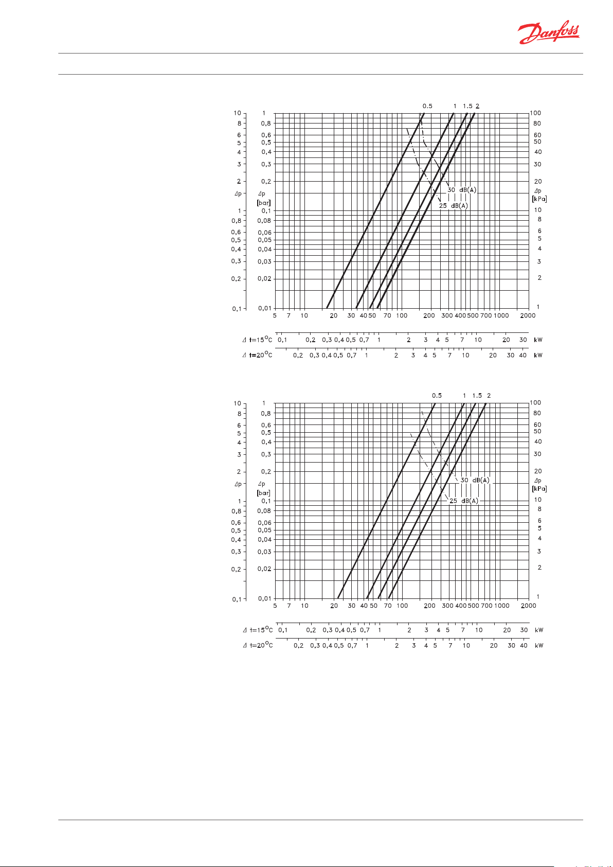
RA-FN DN10
[mwg]
Q [l/h]
RA-FN DN15
[mwg]
Q [l/h]
Data Sheet Fixed Capacity ValvesType RA-FN (Series F)
Capacities
Danfoss Heating Solutions VDSXI202 © Danfoss 12/2010 3
Page 4

RA-FN DN20, DN25
[mwg]
Q [l/h]
RA-FN DN20 horiz. angle
[mwg]
Q [l/h]
Data Sheet Fixed Capacity ValvesType RA-FN (Series F)
All curves: capacity with p-band of 0.5K, 1K, 1.5K and 2K with RA 2000 sensor.
Note:
As with any device which imposes a pressure
drop in the system, noise may occur under
certain flow/pressure conditions. To ensure
quiet operation, maximum pressure drop
should not exceed 30-35 kPa (3-3.5 mwg).
4 VDSXI202 © Danfoss 12/2010 Danfoss Heating Solutions
Page 5

D
L
2
L
1
d
2
d
1
S
1
S
2
H
2
H
1
H
3
S
2
d
2
d
1
S
1
D
L
3
L
4
L
5
H
1
H
2
H
3
Data Sheet Fixed Capacity ValvesType RA-FN (Series F)
Design
A radiator thermostat consists of a thermostatic
element of the RA 2000 series and an RA-FN
The element and the valve body are ordered
separately.
valve.
Materials in contact with water
Valve body and other metal parts Ms 58, brass
O-ring EPDM
Valve cone NBR
Pressure pin and valve spring Chrome/Steel
Nozzle PP
1. Gland seal
2. O-Ring
3. Pressure Pin
4. Seal
5. Regulation spring
7. Valve body
8. kv-nozzle
The RA-FN valves are nickle-plated on the outside.
Dimensions
RA-FN straight valve RA-FN angle valve
Danfoss Heating Solutions VDSXI202 © Danfoss 12/2010 5
Page 6

L
4
L
3
D
S
1
d
1
d
2
S
2
H
3
H
1
H
2
L
5
Data Sheet Fixed Capacity ValvesType RA-FN (Series F)
RA-FN horizontal angle valve
Series F
ISO 7-1
D
d
1
L1L2L3L4L5H1H2H
d
2
3
Arc. flats
S1S
RA-FN 10 G 3/8 G 5/8 A R 3/8 50 75 24 49 20 47 50 15 22 27
RA-FN 10 horiz. G 3/8 G 5/8 A R 3/8 - - 26 51 22 61 64 29 22 27
RA-FN 15 G 1/2 G 3/4 A R 1/2 55 82 26 53 23 47 50 15 27 30
RA-FN 15 horiz. G 1/2 G 3/4 A R 1/2 - - 29 57 27 62 65 30 27 30
RA-FN 20 G 3/4 G 1/1 A R 3/4 65 98 30 63 26 47 50 15 32 37
RA-FN 20 horiz. G 3/4 G 1/1 A R 3/4 - - 34 66 30 63 66 31 32 37
RA-FN 25 G 1/1 G 1/1 A R 1/1 90 125 40 75 34 47 50 15 41 46
1
6 VDSXI202 © Danfoss 12/2010 Danfoss Heating Solutions
Page 7

Data Sheet Fixed Capacity ValvesType RA-FN (Series F)
Danfoss Heating Solutions VDSXI202 © Danfoss 12/2010 7
Page 8

Data Sheet Fixed Capacity ValvesType RA-FN (Series F)
Danfoss A/S
Heating Solutions
Haarupvaenget 11
8600 Silkeborg
Denmark
Phone:+45 7488 8000
Fax: +45 7488 8100
Email: heating.solutions@danfoss.com
www.heating.danfoss.com
Danfoss can accept no responsibility for possible errors in catalogues, brochures and other printed material. Danfoss reserves the right to alter its products without notice. This also applies to products
already on order provided that such alterations can be made without subsequential changes being necessary in specifications already agreed. All trademarks in this material are property of the respective
companies. Danfoss and the Danfoss logotype are trademarks of Danfoss A/S. All rights reserved.
8 VDSXI202 © Danfoss 12/2010 Danfoss Heating Solutions
 Loading...