

Page 1
Data sheet
RA-C valves for cooling and heating circuits
Description
Ordering and Specification
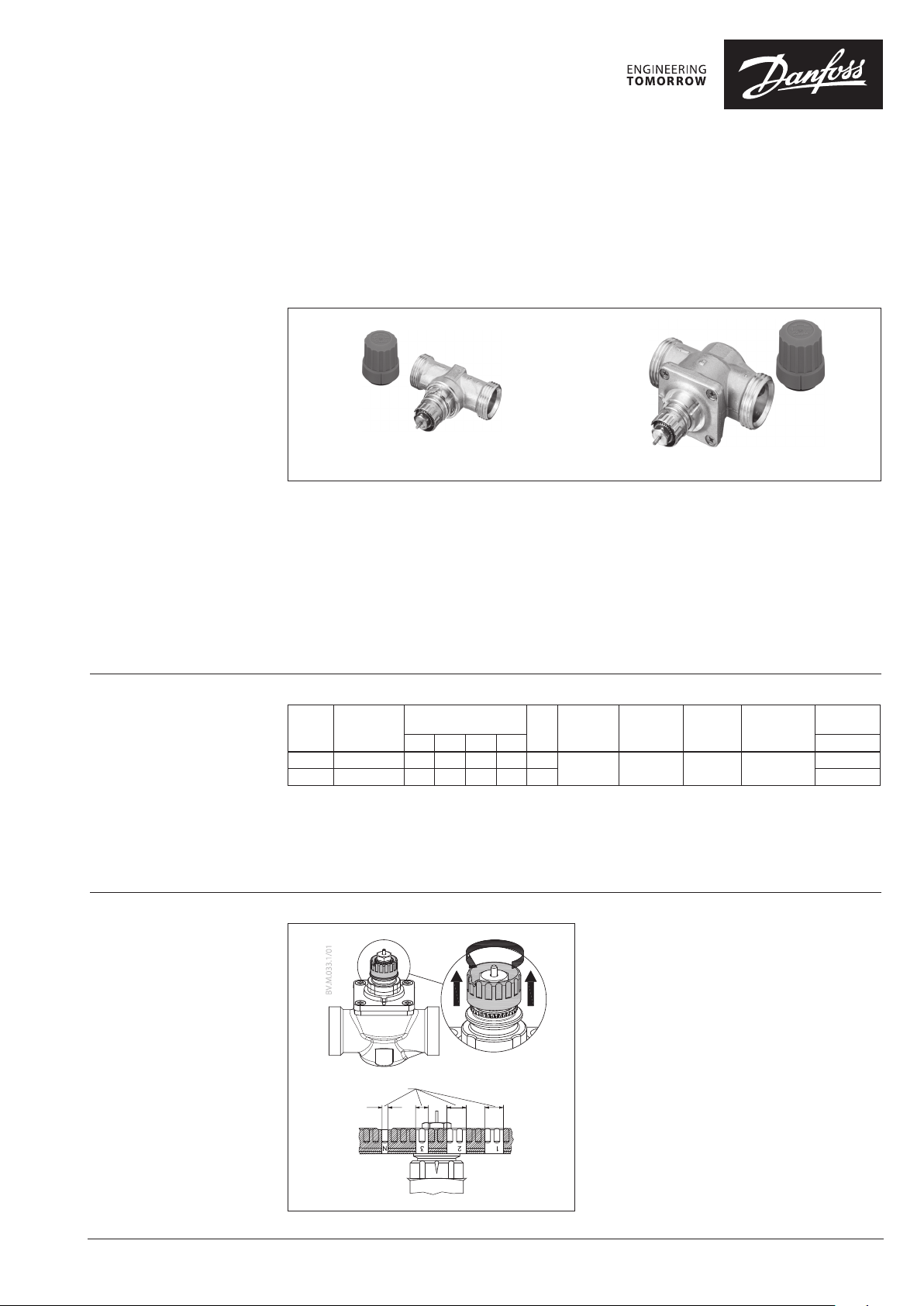
RA-C 15 cooling valve
Together with Danfoss selfacting and electronic
controls, RA-C valves make up a perfect
combina-tion for control of cooling and heating
circuits.
The RA-C valve is a normally open valve. In an
application with self-acting sensors type FEK or FED
it is ensured that the cooling valve opens when the
room temperature is rising above the set temperature.
The RA-C valve has 4 presettings, thus the correct
quantity of water is ensured for each cooling circuit
and it is PN16 approved.
The valve has two external threads thus fittings for
various pipe types may be mounted.
Moreover, Danfoss can also offer a comprehensive
range of fittings (see back page).
RA-C 20 cooling valve
Shut-off (for isolation during system maintenance)
using manual shut off knob
Presettings:
Valve
Connections
RA -C 15 2 × G ⁄ A 0.30 0.55 0.75 0.90 1.20
RA-C 20 2 × G 1 A 0.80 1.10 1.70 2.60 3.30 013G3096
1)
The kv-val ues show the flow (Q) in m3/h at a dif ferential pressure (∆p) of 1 bar thr ough the valve. At presettin g N the kv-value is shown
at Xp = 3 K. The X p-value decreases at lowe r presettings thus the kv -value at presetting 1 is show n at Xp = 1 K.
2)
The max. di fferential pressure spe cified is the maximum pre ssure at which the valves give satisfac tory regulation. As wi th any device
which imposes a p ressure drop on the system, no ise may occur under certain f low/pressure conditions. A dif ferential pressure bet ween 0.1
and 0.3 bar ac ross the valves is recommended. T he differential pressur e can be reduced using Danfoss dif ferential pressure regul ators. 2)
3)
Shut-off PN10 approved.
kv-value1), m3/h
1 2 3 N
Max.
k
working
vs
pressure
10 ba r 0.6 bar 16 ba r 10 - 120°C
differential
3)
pressure
Max.
2)
Tes t
pressure
Water
temperature
Code No.
013G3094
Presetting With the valve body type RA-C the calculated setting
can be set easily and exactly without using special
tools:
• remove the protective cap or sensor element,
• raise the setting ring,
• turn the scale on the setting ring until the required
scale value faces the reference mark,
• release the setting ring.
The presetting can be set at the values: 1- 2 - 3 and N.
At setting N, the valve is completely open.
A setting in the shaded areas should be avoided.
When the sensor element is mounted, the pre-setting
is hidden, and is thus protected against alteration.
VD.33.U5.02 | 1
© Danfoss | 2018.12
Presetting range
①
②
Page 2
Data sheet RA-C valves for cooling and heating circuits
Pressure and noise
conditions
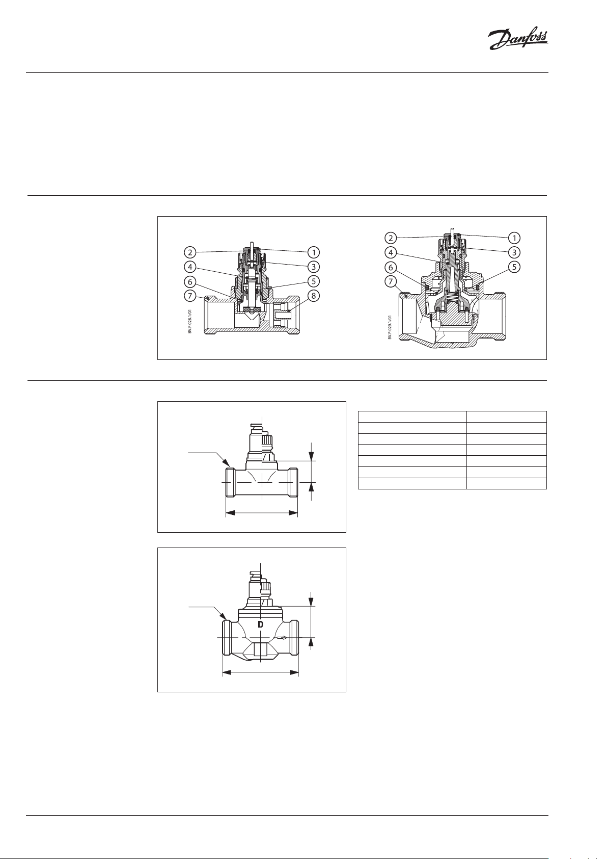
Design
1. Gland seal
2. O-ring
3. Pressure pin
4. Seal
5. Regulation spring
6. Presetting bush
7. Valve body
8. KV-nozzle
Special demands are made on the various
components of the system. This is due to water
temperature conditions, the chosen pipe types and
pipe dimensions of both chilled ceilings and fancoils/
induction units and the structure of the cooling
circuits.
In chilled ceilings and fancoils/induction-units
relatively large differential pressure and water flow are
RA- C 15
often used compared to normal heating systems. This
may lead to noise nuisance.
The RA-C valve has especially been designed to
correspond to these demands, no matter whether
selfacting or electronic controls are used.
RA-C 20
Dimensions Materials in contact with flow medium
RA- C 15
G ⁄ A
20
66
Valve body and other metal parts Corrosion resistant brass
Spindle Corrosion resistant brass
Throttle nozzle PPS
O-rings EPDM
Valve cone NBR
Gland seal pressure pin Chrome steel
kv-nozzle PP
1)
Flow medium: water and water mixture s with secondary
coolants like gl ycols (regarding suitability an d usage especially
in not oxyge n tight systems please see the ins tructions given by
the coolant pro ducer) .
RA-C 20
G 1 A
30.5
74
1)
2 | VD.33.U5.02
© Danfoss | 2018.12
Page 3

Data sheet RA-C valves for cooling and heating circuits
[m
[m
Capacities
RA- C 15
wg]
RA-C 20
wg]
Sizing example, chilled ceiling:
Cooling demand: Φ = 0.55 kW
System temperature rise: ∆t = 2 °C
Differential pressure: ∆p = 0.1 bar
Calculated water quantity: Q =
The setting is found in the capacity diagramme: RA- C 15: Presetting value 3
RA-C 20: Presetting value 1
Capacities with P-band between 1 and 3 K
550
2 × 1.16
= 237 l/h
© Danfoss | 2018.12
VD.33.U5.02 | 3
Page 4

Danf
already on order pro
All trademarks in this material are property of the respec
Data sheet RA-C valves for cooling and heating circuits
Accessories:
Compression fittings for PEX
plastic tubing
Compression f ittings are for connecting
Danfoss valves to circu its in heating
systems only. Compre ssion fittings are
used for connec ting PEX plastic tubings
in accordance with DIN
1689 2/168 93.
Maximum op erating pressure and
temperature are g iven by the tubing
manufacture r. However, 10 bar and 95°
C must not be excee ded.
One set consists of o ne olive, one
supporti ng bush and one union nut.
Einbau im Vor- oder Rück lauf
Compression fittings for Alupex
tubing
Compression f ittings are for connecting
Danfoss valves to circu its in heating
systems only. When con necting circuits
with compression f ittings for Alupex
tubing, alway s observe the maximum
operating pressu re and temperature
which are given by the t ubing
manufacture r. However, 10 bar and 95°
C must not be excee ded.
One set consists of o ne olive, one
supporti ng bush, one insulation washer
and one union nut.
Picture
External thread
Internal thread
Picture
External thread
Internal thread
For PEX pla stic tubing
Connection
G ¾”, internal thread
For PEX pla stic tubing
Connection
G ¾”, internal thread
Tube
dimension
12 × 2 mm 6 bar 10 bar 95 °C 013G 4152
13 × 2 mm 6 bar 10 bar 95 °C 013G 4153
14 × 2 mm 6 bar 10 bar 95 °C 013G 4154
15 × 2.5 mm 6 bar 10 bar 95 °C 013G 415
16 × 1.5 mm 6 bar 10 bar 95 °C 013G4157
16 × 2 mm 6 bar 10 bar 95 °C 013G 4156
16 × 2.2 mm 6 bar 10 bar 95 °C 013G 4163
17 × 2 mm 6 bar 10 bar 95 °C 013G4162
18 × 2 mm 6 bar 10 bar 95 °C 013G 4158
18 × 2.5 mm 6 bar 10 bar 95 °C 013G 4159
20 × 2 mm 6 bar 10 bar 95 °C 013G 4160
20 × 2.5 mm 6 bar 10 bar 95 °C 013 G4161
Tube
dimension
12 × 2 mm 6 bar 10 bar 95 °C 013G4182
14 × 2 mm 6 bar 10 bar 95 °C 013G4184
15 × 2.5 mm 6 bar 10 bar 95 °C 013G4185
16 × 2 mm 6 bar 10 bar 95 °C 013G 4186
16 × 2.25 mm 6 bar 10 bar 95 °C 013G 4187
18 × 2 mm 6 bar
20 × 2 mm
20 × 2.5 mm 6 bar 10 bar 95 °C 013 G4191
Max. working
pressure
Max. working
pressure
6 bar 10 bar 95 °C 013G4190
Tes t
pressure
Tes t
pressure
10 ba r
Max. flow Code No.
Max. flow Code No.
95 °C 013G4188
Compression fittings for steel and
copper tubing
Compression f ittings are for connecting
Danfoss valves to circu its in heating
systems only. Compre ssion fittings
are used for connec ting steel and
copper pip es in accordance with DIN
178 6/ 2391.
One set consists of o ne olive and one
union nut. It is recom mended to use
supporti ng bushes with soft pipes.
Picture
External thread
Internal thread
For PEX pla stic tubing
Connection
G ¾”, internal thread
G 1”
Manual shut off knob, high pressure 013G 3300
Manual shut off knob 013G 5002
Raccords pour joints plats Pour RAC 15 003L0294
Raccords pour joints plats Pour RAC 20 003Z4072
Tube
dimension
10 mm 10 bar 16 ba r 12 0 °C 013G412 0
12 m m 10 ba r 16 bar 120 °C 013G 4122
14 mm 10 b ar 16 bar 12 0 °C 013G4124
15 mm 10 bar 16 b ar 120 °C 013G 4125
16 mm 10 bar 16 bar 12 0 °C 013G4126
18 mm 10 bar 16 bar 12 0 °C 013G4128
18 mm 10 bar 16 bar 12 0 °C 013U0134
22 mm 10 bar 16 bar 120 ° C 013U 0135
Max. working
pressure
Tes t
pressure
Max. flow Code No.
oss can accept no responsibility for possible errors in catalogues, brochures and other printed material. Danfoss reserves the right to alter its products without notice. This also applies to products
vided that such alterations can be made without subsequential changes being necessary eady agreed.
4 | VD.33.U5.02
tive companies. Danfoss and the Danfoss logotype are trademarks of Danfoss A/S. All rights reserved.
© Danfoss | DHS-SRMT/SI | 2018.12
 Loading...