

Page 1

Data sheet RA-C valves
for cooling and heating circuits
Products
RA-C 15
Together with Danfoss selfacting and electronic controls, RA-C valves make up a perfect combination for control of cooling and
heating circuits.
The RA-C valve is a normally open valve. In
The RA-C valve has 4 presettings, thus the
correct quantity of water is ensured for each
cooling circuit.
The valve has two external threads thus fittings for various pipe types may be mounted.
RA-C 20
an application with self-acting sensors type
FEK or FED it is ensured that the cooling
valve opens when the room temperature is
Moreover, Danfoss can also offer a comprehensive range of fittings (see back page).
rising above the set temperature.
Specifications
Presettings: kv-value 1), m3/h Max. Max.
Valve Code no. Connections k
RA-C 15 013G3094 2 x G 3/4 A 0.30 0.55 0.75 0.90 1.20
RA-C 20 013G3096 2 x G 1 A 0.80 1.10 1.70 2.60 3.30
1) The kv-values show the flow (Q) in m3/h at a differential pressure (Dp) of 1 bar through the valve. At presetting N the kv-value is shown at Xp
= 3 K. The Xp-value decreases at lower presettings thus the k
2) The max. differential pressure specified is the maximum pressure at which the valves give satisfactory regulation. As with any device which
imposes a pressure drop on the system, noise may occur under certain flow/pressure conditions. A differential pressure between 0.1 and 0.3
bar across the valves is recommended. The differential pressure can be reduced using Danfoss differential pressure regulators.
1 2 3 N pressure pressure
-value at presetting 1 is shown at Xp = 1 K.
v
working diff.
vs
10 bar 0.6 bar 16 bar 10 - 120 °C
Test- Water
2)
pressure temperature
Presetting With the valve body type RA-C the calculated
setting can be set easily and exactly without
using special tools:
- remove the protective cap or sensor element,
- raise the setting ring,
- turn the scale on the setting ring until the
required scale value faces the reference
mark,
- release the setting ring.
The presetting can be set at the values: 1- 2 3 and N.
At setting N, the valve is completely open. A
Presetting area
setting in the shaded areas should be avoided. When the sensor element is mounted, the
presetting is hidden, and is thus protected
against alteration.
CD-ST VD.33.U1.02 © Danfoss 06/99 1
Page 2
Data sheet Climate controls: RA-C valves
Pressure and noise conditions
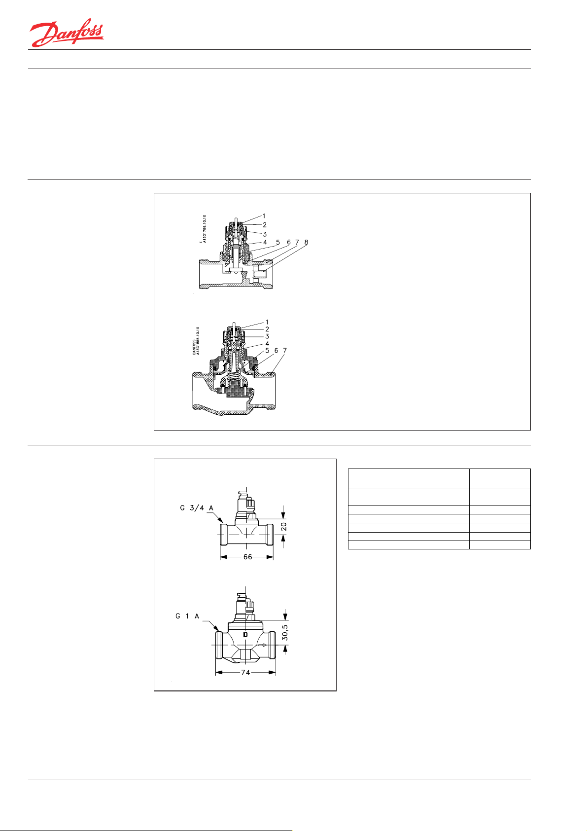
Design
Special demands are made on the various
components of the system.
This is due to water temperature conditions,
the chosen pipe types and pipe dimensions of
both chilled ceilings and fancoils/induction
units and the structure of the cooling circuits.
In chilled ceilings and fancoils/induction-units
RA-C 15
RA-C 20
relatively large differential pressure and water
flow are often used compared to normal heating systems. This may lead to noise nuisance.
The RA-C valve has especially been designed
to correspond to these demands, no matter
whether selfacting or electronic controls are
used.
1. Gland seal
2. O-ring
3. Pressure pin
4. Seal
5. Regulation spring
6. Presetting bush
7. Valve body
-nozzle
8. k
v
Dimensions
RA-C 15
RA-C 20
Materials in contact with water
Valve body and other metal parts
Spindle
Throttle nozzle PPS
O-ring EPDM
Valve cone NBR
Pressure pin in gland seal Chrome steel
Nozzle PP
Corrosionresistant brass
Corrosionresistant brass
2 VD.33.U1.02 © Danfoss 06/99 CD-ST
Page 3

Data sheet Climate controls: RA-C valves
Capacities
RA-C 15
RA-C 20
Sizing example, chilled ceiling:
Cooling demand: ................................... F = 0.55 kW
System temperature rise: ............................ Dt = 2 °C
Differential pressure: ............................. Dp = 0.1 bar
Calculated water quantity: Q = = 237 l/h
550
2 x 1.16
The setting is found in the capacity diagramme:
RA-C 15: Presetting value 3,
RA-C 20: Presetting value 1.
Capacities with P-band between 1 and 3 K
CD-ST VD.33.U1.02 © Danfoss 06/99 3
Page 4

Data sheet Climate controls: RA-C valves
Accessories:
Fittings
For PEX plastic tubing Tube Code no. Max. working Test Max. flow
Connection dimension pressure pressure temperature
G 3/4, 16x1.5 mm 013G4157 6 bar 10 bar 95° C
internal thread 16x2 mm 013G4156
For Alupex tubing Tube Code no. Max. working Test Max. flow
Connection dimension pressure pressure temperature
G 3/4, 16x2 mm 013G4186 6 bar 10 bar 95° C
internal thread 16x2.25 mm 013G4187
For steel and copper tubing Tube Code no. Max. working Test Max. flow
Connection dimension pressure pressure temperature
G 3/4, 14 mm 013G4124
internal thread 15 mm 013G4125 10 bar 16 bar 120 °C
G 1
12x2 mm 013G4152
13x2 mm 013G4153
14x2 mm 013G4154
15x2.5 mm 013G4155
16x2.2 mm 013G4163
17x2 mm 013G4162
18x2 mm 013G4158
18x2.5 mm 013G4159
20x2 mm 013G4160
20x2.5 mm 013G4161
12x2 mm 013G4182
14x2 mm 013G4184
15x2.5 mm 013G4185
18x2 mm 013G4188
20x2 mm 013G4190
20x2.5 mm 013G4191
10 mm 013G4120
12 mm 013G4122
16 mm 013G4126
18 mm 013G4128
18 mm 013U0134
22 mm 013U0135
VD.33.U1.02 © Danfoss 06/99 CD-ST
 Loading...