

Page 1
Data Sheet
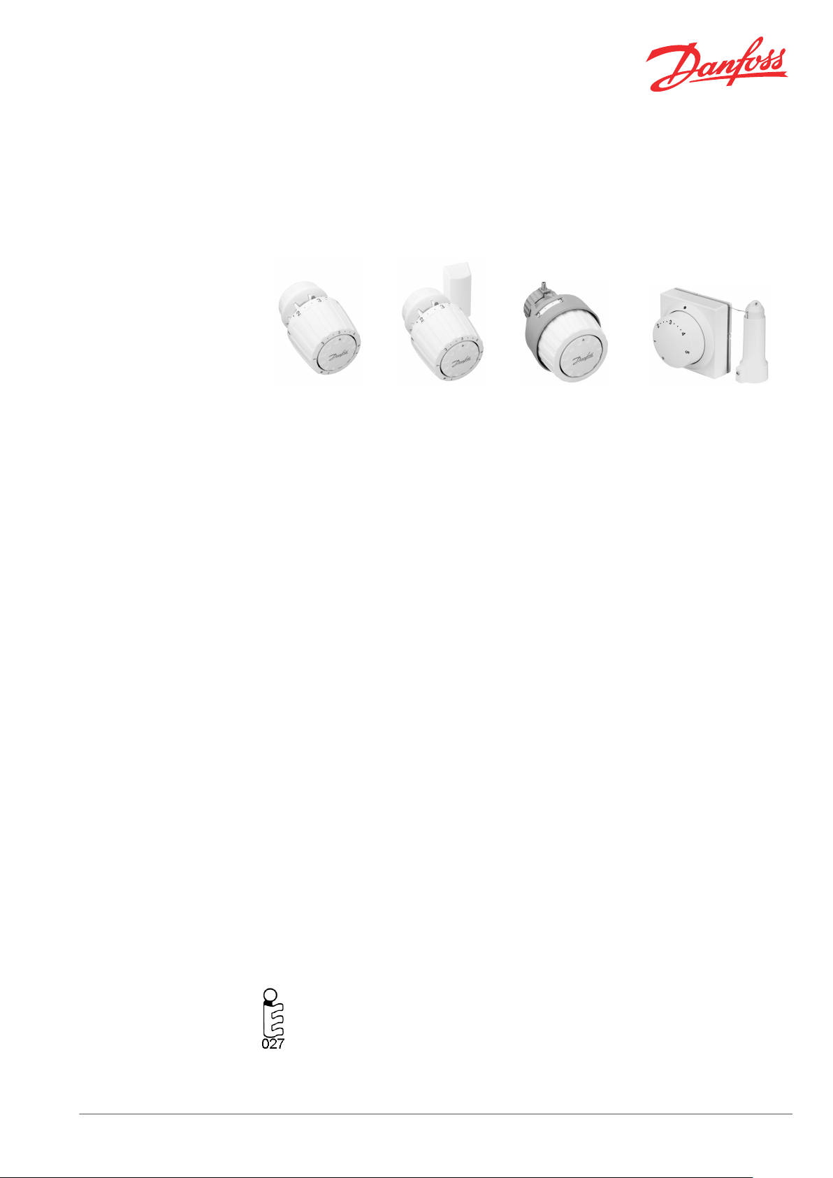
Thermostatic Sensors Type RA 2000
Application
RA 2990 RA 2992 RA 2920 RA 5060
The RA series is a comprehensive programme of
radiator thermostats which covers all central and
district heating systems.
RA is a self-actuating proportional controller with
a small P-band.
The RA sensor range includes:
RA 2990: built-in sensor with frost
▪
protection, temperature range 5-26°C,
facilities for limiting and locking the
temperature set-point. A score on energy
efficiency. RA 2990 and 2992 sensors are
equipped with a snap-lock mechanism
which ensures quick, firm and long lasting
mounting of the sensor.
RA 2992: remote sensor with frost
▪
protection, temperature range 5-26°C,
facilities for limiting and locking the
temperature set-point.
RA 2920: Tamperproof model with built-in
▪
sensor, frost protection, temperature range
5-26°C, facilities for limiting and locking the
temperature set-point.
RA 2922: Tamperproof model with remote
▪
sensor, frost protection, temperature range
5-26°C, facilities for limiting and locking the
temperature set-point.
RA 2992 and 2922 are equipped with 2 m of ultrathin capillary tube, which is coiled up within the
remote sensor housing. After sensor mounting
capillary tube is pulled out to the required length.
range 8-28°C, facilities for limiting and
locking the temperature set-point.
RA 5062: length of capillary tube 2 m
▪
RA 5065: length of capillary tube 5 m
▪
RA 5068: length of capillary tube 8 m
▪
The snap-lock sensors are easy to mount and
requires no use of tools.
The sensor is fitted to the valve by applying a
gentle pressure. When the sensor is in place, the
snap-on mechanism is activated and the sensor
has been correctly mounted.
If mounting and dismounting are carried out
again, the mechanism must be tightened
manually by turning the tightening ring.
All thermostatic sensors can be combined with all
RA 2000 valve bodies.
The technical data for RA valve bodies in
combination with RA sensors meet Euronorm EN
215.
RA 5060 Series: remote temperature
▪
adjuster with frost protection. Temperature
Approved to EN 215
Danfoss Heating Solutions VD51A602 © Danfoss 05/2011 1
Thermostatic sensors type RA 2000 are
manufactured to the highest standards,
and are approved to the European
standard EN 215.
Page 2
Data Sheet Thermostatic Sensors Type RA 2000
Ordering and
Specifications
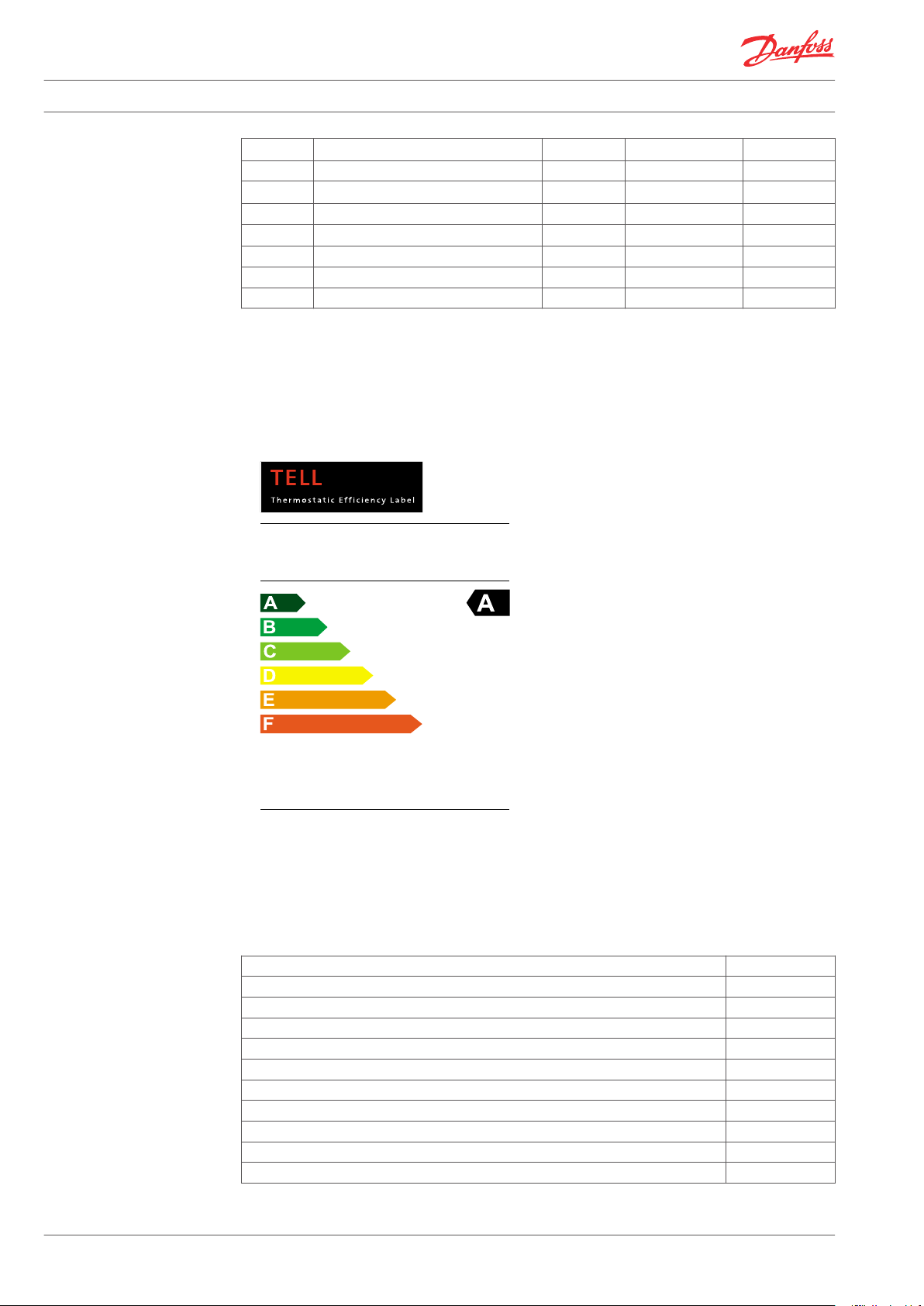
Thermostatic Efficiency
Label
Type Model Cap. tube
Temp. range
2)
Code no.
RA 2990 Standard , built-in sensor - 5-26 °C 013G2990
RA 2992 Standard, remote sensor
0-2 m
1)
5-26 °C 013G2992
RA 2920 Tamperproof, built-in sensor - 5-26 °C 013G2920
RA 2922 Tamperproof, remote sensor
0-2 m
1)
5-26 °C 013G2922
RA 5062 Remote temperature adjuster 2 m 8-28 °C 013G5062
RA 5065 Remote temperature adjuster 5 m 8-28 °C 013G5065
RA 5068 Remote temperature adjuster 8 m 8-28 °C 013G5068
1)
The remote sensor is delivered with all of the capillary tube coiled up within the sensor. When
mounting the sensor, only the capillary tube required is uncoiled.
2)
Temperatures stated for Xp = 2K, i.e. the valve is closed at 2 °C higher room temperature.
Manufacturer:
Model:
Registrationnumber:
Danfoss
RA2990
10557-20141015
Information:www.tellonline.eu
ALabelofEUnitedValves
EuropeanValveManufacturersAssociation
Accessories
Product Code no.
Manual setting knob for RA valves, plastic 013G5002
Manual setting knob for RA valves, brass 013G3300
Limiting pins for RA 2990/92 (30 pcs.) 013G1215
Limiting pins for RA 2920/22 (30 pcs.) 013G1237
Anti-theft plugs for RA 2990/92 (20 pcs.) 013G5245
Scale cover for RA 2920/22 (20 pcs.) 013G1672
Toolkit, Allen key & locking pin tool 013G1236
Compact adaptor for RA 5062/65/68 to RA 2000 valves 013G5190
Adaptor for RA 5062/65/68 to RA 2000 valves 013G5191
Adaptor for RA 5062/65/68 to M30x1.5 valves 013G5194
2 VD51A602 © Danfoss 05/2011 Danfoss Heating Solutions
Page 3
T
7 9,5 14 17 20 23 26 28°C
l
*
5 7,5 13 15 18 21 24 26°C
1 2
3 4
5
l
.
...
T
10 14 18 22 26 30°C
*
8 12 16 20 24 28°C
1
2
3 4
5
. .. ...
Data Sheet Thermostatic Sensors Type RA 2000
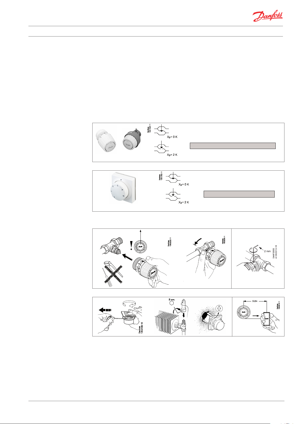
Setting the Temperature
The required room temperature is set by turning
the setting dial. The temperature scales show the
correlation between scale values and the room
temperature. The temperature values stated are
for guidance only as the obtained room
temperature will often be influenced by
installation conditions.
The temperature scales are stated according to
European standards at Xp = 2°C. This means that
the radiator thermostats close at a sensor
temperature which is 2°C higher than stated on
the temperature scales.
RA 2990 /92 RA 2920/22
Locking and limitation of the temperature setpoint of RA sensors are carried out using the
limiter pins placed at the back of the sensor.
Locking and max/min limitation of the remote
temperature adjuster type RA 5060 are carried
out by the limiter tabs. The limiter tabs will be
covered by the setting dial.
The procedure is described in the instruction.
= Frost protection setting
= Frost protection setting
Mounting
RA 5062, RA 5065, RA 5068
Danfoss Heating Solutions VD51A602 © Danfoss 05/2011 3
Page 4

Data Sheet Thermostatic Sensors Type RA 2000
Choose the Right Sensor
The thermostatic sensor should be selected on
the basis of the following criteria:
The sensor must always be able to register the
temperature of the ambient air.
Radiator thermostats with built-in sensors These
should always be fitted horizontally so that the
ambient air can pass freely over the sensor.
Danfoss does not recommend the fitting of a
built-in sensor in vertical position because heat
effect from the valve body and possibly surface
pipes will cause incorrect operation of the
thermostat.
Radiator thermostats with remote sensor
These should be used when:
Curtains cover the sensor
▪
Sensor is affected by surface pipes
▪
Sensor is affected by draught
▪
It is necessary to mount the sensor in
▪
vertical position if there are adjacent
obstructions.
The remote sensor must be mounted on the wall,
away from curtains, or on the skirting board
beneath the radiator if free of surface pipes. All
remote sensors are now supplied with ultra-thin
capillary tube. Simply pull out the length
required (2 m maximum) and fix using clips
provided or special tacker gun.
Radiator valves with remote adjustment
The remote temperature adjuster is used on
radiators or convectors which are hidden in a
cabinet or in other ways inaccessible to the user.
In addition, the room temperature adjuster is
used in integral sockets and installation ducts.
The sensor and the setting part of a remote
setting unit are integrated.
The remote temperature adjuster is placed in an
easily accessible place where the ambient air can
at the same time pass freely over the sensor. This
is ideal where the valve is inaccessible to the user.
The temperature adjuster should be mounted
between 1.2 and 1.6 m above the floor.
4 VD51A602 © Danfoss 05/2011 Danfoss Heating Solutions
Page 5

1
Data Sheet Thermostatic Sensors Type RA 2000
Sensor Operation
Principle
1. Actuator
2. Bellows
3. Setting dial
4. Setting spring
5. Spindle
6. Remote sensor
7. Capillary tube
1. Actuator
2. Setting part
3. Setting bellows
4. Operation bellows
5. Valve adaptor
6. Capillary tube, rolled up
Max. ambient sensor temperature: 60°C.
Dimensions
Standard model RA 2990
Model with remote sensor RA 2992
Tamperproof model RA 2920
Remote temperature adjuster RA 5060
Danfoss Heating Solutions VD51A602 © Danfoss 05/2011 5
Page 6

Data Sheet Thermostatic Sensors Type RA 2000
6 VD51A602 © Danfoss 05/2011 Danfoss Heating Solutions
Page 7

Data Sheet Thermostatic Sensors Type RA 2000
Danfoss Heating Solutions VD51A602 © Danfoss 05/2011 7
Page 8

Data Sheet Thermostatic Sensors Type RA 2000
Danfoss A/S
Heating Solutions
Haarupvaenget 11
8600 Silkeborg
Denmark
Phone:+45 7488 8000
Fax: +45 7488 8100
Email: heating.solutions@danfoss.com
www.heating.danfoss.com
Danfoss can accept no responsibility for possible errors in catalogues, brochures and other printed material. Danfoss reserves the right to alter its products without notice. This also applies to products
already on order provided that such alterations can be made without subsequential changes being necessary in specifications already agreed. All trademarks in this material are property of the respective
companies. Danfoss and the Danfoss logotype are trademarks of Danfoss A/S. All rights reserved.
8 VD51A602 © Danfoss 05/2011 Danfoss Heating Solutions
 Loading...