

Page 1
Data Sheet
Thermostatic Radiator Sensor, Type RA2914
Limited to 20°C
Application
The RA 2914 sensor regulator with a narrow
proportional band. It is compatible with all
valve bodies of the RA series.
The head is provided with antifreeze protection. A factory-fitted metal stop limits the setting to 20°C. A miniature screw can be added.
A hexagon socket screw ensures a simple and
effective mounting of the head on the valve
body (see mounting) .
Quality
Coefficient de Variation
Temporelle
Features - Thermostatic valves functioning
Thermostatic sensors RA2914 are manufactured to the highest standards, and are
approved to the European standard EN
215.
RA2914: Vt = 0,5 K
autonomously without auxiliary power
- Limited to a setpoint of 21°C via a factory
fitted metal stop and screw.
Used with the RA valve bodies, its technical
characteristics meet the European standard
EN 215.
The color corresponds to the RAL 9016 standard (pure white).
All Danfoss radiator thermostats are manufactured in factories, assessed and certified
against ISO 9001and ISO 14001.
- Comfort in heating and very good
recovery (energy saving)
- Aesthetic that integrates with any interior
(Colour: RAL 9016)
Ordering and
Specifications
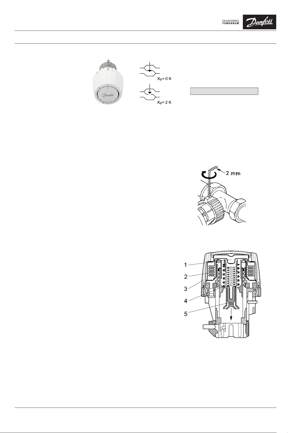
1) Xp = 2K (the valve closes at 2 °C higher room temperature)
Accessories Code No.
Hex Allen Key, Key for limiter 013G1236
Additional limiting clamps (batch of 30 pins) 013G1237
VDLTD102 © Danfoss 02/2017 1
Model
RA2914 Built in sensor 5-20 °C 013G2914
Type Setting Range 1) Code No.
Page 2
7 14 17 20 22 9,5 °C
1
2
• • 3 •
5 13 15 18 20 °C
|
7,5
Datasheet Thermostatic Radiator Sensor, Type RA2914 - Limited to 20°C
Setting the Temperature
* = Frost protection setting
Ambient temperatures refer to the index
above. The indications given are only indicative as the mounting conditions and various
factors influence the temperature obtained.
Mounting The mounting of the head on the valve body
is very simple: position the head, then fix
with the Allen screw.
Construction 1. Actuator
2. Bellows
3. Setting dial
4. Setting spring
5. Spindle
In addition to the stop at 20 ° C, the marking
stops at index 3
VDLTD102 © Danfoss 02/2017 2
Page 3

Datasheet Thermostatic Radiator Sensor, Type RA2914 - Limited to 20°C
Dimensions
Danfoss A/S
Heating Solutions
Haarupvaenget 11
8600 Silkeborg
Denmark
Phone: +45 7488 8000
Fax: +45 7488 8100
e-mail: heating.solutions@danfoss.com
www.heating.danfoss.com
3 VDLTD102 © Danfoss 02/2017
 Loading...