

Data sheet RA 15/6T valve for one-pipe systems
RA 15/6TB valve for two-pipe systems
Application
Applications
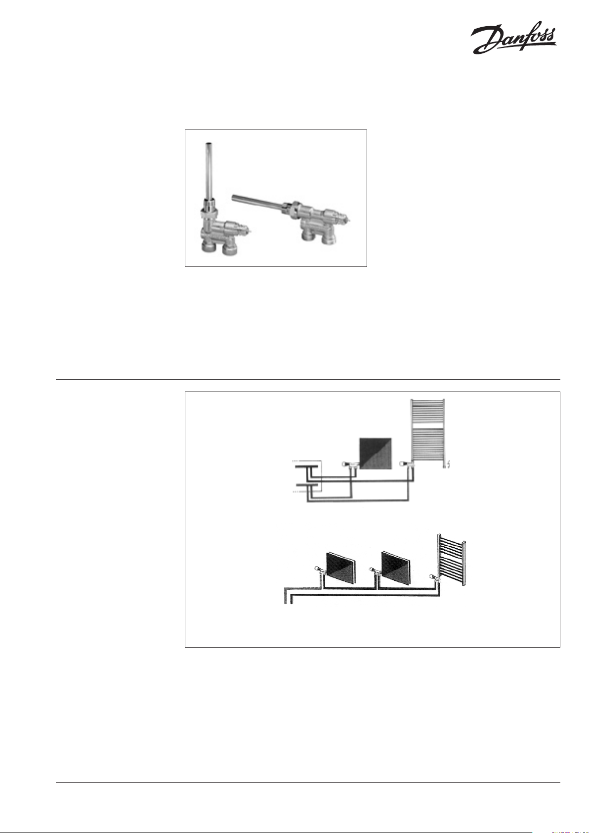
The RA 15/6T and TB are special lance (bypass)
valves, which allows the radiator to be connected
at one point only - underneath or at the side of
the radiator, as required.
It is designed for conventional one- and two-pipe
systems with pumped circulation and has xed
kv-values.
In one-pipe systems, the system water ows
partly through the radiator and partly through
the built-in bypass into the valve.
Ecient mounting is enabled by a range of compression ttings for steel, copper, PEX and AluPEX
pipes.
To prevent scale and corrosion, the system water
should comply with VDI (Verein Deutscher Ingenieure) guideline 2035.
Depending on the type of radiator, a bae plate
or special connector, may be required.
Please note, when a bypass valve is tted, not all
radiators will provide the performance quoted
in their catalogue, and variations in performance
may occur, where dierent radiators are combined.
In these cases, please ask your radiator manufacturer for detailed information.
RA 15/6T valve bodies can be tted with RA 2000
thermostatic sensors and TWA thermal actuators.
Two-pipe system with RA 15/6TB
‚
One-pipe system with RA 15/6T
Electricalheat cartridge
·
DKCD VK.TQ.U4.02 © Danfoss 02/2008 1
Data sheet
2 VK.TQ.U4.02 © Danfoss 02/2008 DKCD
Lance valves RA 15/6T and RA 15/6TB
Technical data and ordering
Type RA 15/6TB for two-pipe systems
ISO 7-1 connections
Valve with Code no.
oor connections 013G3210
wall connections 013G3215
System Radiator working
Rp 1/2 R 1/2 0,29 0,51 0,70 0,82 1,00 10 0,6 16 120
Typ RA 15/6T für Einrohranlagen
ISO 7-1/228-1 connections
Valve with Code no.
System Radiator
oor connections
wall connections
1)
kvs = kv bypass + kv radiator. Max. ow through radiator, approx. 35%.
2)
Working pressure = Static pressure + dierential pressure .
2)
Connection cone geometry according to DIN V3838
013G3220
013G3218 G 3/4 ext. thread
013G3270 Rp 1/2 int. thread
013G3268 G 3/4 ext. thread
Rp 1/2 int. thread
3)
3)
kv-values
1) m3
at Xp
0,5 1,0 1,5 2,0
1)
k
vs
2,15
R 1/2
2,0
/h
k
Max. pressure (bar)
vs
dierential
test
Max. pressure (bar)
3)
working
10 0,6 16 120
dierential test
Max. ow
°C
Max.
ow
°C
Accessories
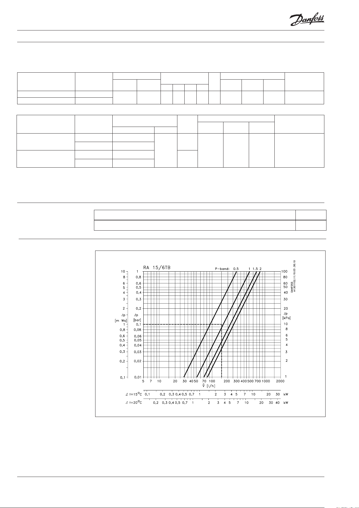
Capacities
in two-pipe systems
Product Code no.
Gland seal (10 pcs.) - can be replaced without draining down the system. 013G0290
Example:
At ∆p = 0,1 bar and
V = 150 l/hand RA-sensor the RA
15/6TB operates with a P-band of
approx. 1.0 K.
.

Data sheet Lance valves RA 15/6T and RA 15/6TB
Dimensioning of
one-pipe systems
Design
1. Pressure pin
2. O-ring gland seal
3. Valve cone
4. Valve body
5. Lance (distribution pipe)
Valve bodies are nickel plated.
RA 15/6T is designed for circuits to max. 9 KW
(8.000 kcal/h) at ∆t = 20 K. With a P-band of 2 K (°C)
ow through the radiator is approximately 30%.
Excess pressure in a riser may be reduced using
Danfoss dierential pressure controls.
Please pay attention to the fact that not all brands
of radiators performs as stated in their documentation when used in one pipe systems with bypass valves.
The radiator manufacturer will inform about
possible reduction in performance.
RA 15/6TB for two-pipe systems
½" connections
RA 15/6T for one-pipe systems
½" connections
Materials in contact with water
Pipe supporting bush PP
O-ring EPDM
Valve cone NBR
Pressure pin Chrome steel
Lock washer Tin alloy
Valve body and other metal parts Ms 58 brass
DKCD VK.TQ.U4.02 © Danfoss 02/2008 3

Data sheet
Dimensions
Lance valves RA 15/6T and RA 15/6TB
Valve with oor connection
1/2" connections
Valve type Connection
H
1
Valve with wall connection
1/2" and 3/4" cnnections
H
2
H
3
H
4
a b
RA 15/6TB, RA 15/6T R 1/2 internal thread 16 32 205 R 1/2
RA 15/6T G 3/4 external thread 20 27 205 21 G 3/4
4 VK.TQ.U4.02 © Danfoss 02/2008 DKCD
 Loading...