

Page 1
Data sheet
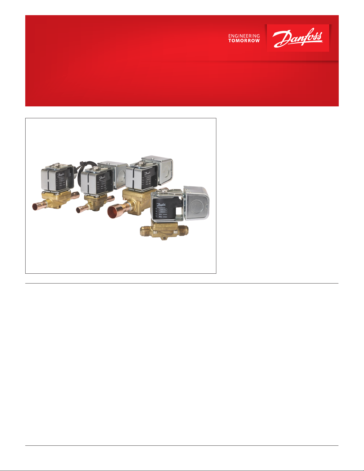
Solenoid valves for R 410A and R744 (CO2)
EVR 2 to EVR 8 and EVRH 10 to EVRH 40
EVR 2 and EVR 3 (direct operated) and EVR 4 to
EVR 8 / EVRH 10 to EVRH 40 (servo-operated) are
high pressure solenoid valves specially designed
to meet the requirements of high pressure
refrigerants such as R410A and R744 (CO2).
The EVRH valve can be used for liquid, suction
and hot gas lines.
Features • Normally Closed and Normally Open
• Coils for AC and DC voltages
• Suitable for R410A and R744 (CO2)
• Media temperatures up to 221°F
• Design pressure 655 psig
© Danfoss | DCS (rja) | 2017.03
• MOPD up to 350 psi
• Solder connections up to 7/8 inch
• Extended soldering ends
• Solders without dismantling the valve
DKRCC.PD.B00.C3.22 | 1
Page 2

Data sheet | Solenoid valves for R410A and R744 (CO2), EVR 2 to EVR 8, EVRH 10 to EVRH 40
Approvals
Technical data
The Low Voltage Directive (LVD) 2014/35/EU with
amendments EN 60730-2-8.
Listed
Temperature of medium
-40 – 105 °C for 10 or 12 W coil
Max. 130 °C during defrost
-40 – 80 °C for 20 W coil
Opening dierential pressure Δp [psig]
Type
Min. ODP
EVR 2 0 350 260 0.19
EVR 3 0 300 260 0.32
EVR 4 0.7 300 260 0.7
EVR 6 0.7 300 260 0.92
EVR 6 NO 0.7 300 300 0.92
EVR 8 0.7 300 260 1.3
EVRH 10 0.7 300 260 2.2
EVRH 15 0.7 300 260 3.0
EVRH 20 0.7 300 190 5.8
EVRH 22 0.7 300 190 6.9
EVRH 25 1.0 300 260 12
EVRH 32 1.0 300 260 18
EVRH 40 1.0 300 260 29
(with standard coil)
14 – 17 W AC 20 W DC
Refrigerants
R744, R22/R407C, R404A/R507, R410A,
R134a, R407A, R23, R744.
For other refrigerants, please contact Danfoss.
Note: EVR 2 – EVR 3 and EVRH 25 – EVRH 40 are not suitable for
R744 (CO2)applications with media temperatures constantly below
0 °C.
For other media temperatures, please contact Danfoss.
MOPD
Cv value
[gal/min]
© Danfoss | DCS (rja) | 2017.03
DKRCC.PD.B00.C3.22 | 2
Page 3

Data sheet | Solenoid valves for R410A and R744 (CO2), EVR 2 to EVR 8, EVRH 10 to EVRH 40
Ordering Solenoid valve – Normally Closed (NC) – Soldering ODF without coil
EVR / EVRH Valves
1)
Type Coil type Connection size [in.] Code no.
EVR 2 AC/DC 1/4
EVR 3
EVR 4
AC/DC 1/4
AC/DC 3/8
AC/DC 3/8
AC/DC 1/2
AC/DC 3/8
EVR 6
AC/DC 1/2
AC/DC 5/8
EVR 8
AC/DC 1/2
AC/DC 5/8
EVRH 10 AC/DC 1/2
EVRH 15 AC/DC 5/8
EVRH 20 AC 7/8
EVRH 25 AC/DC 1 1/8
1)
EVRH 32
AC/DC –
EVRH 40 AC/DC 1 5/8
Only available with mm connections
Solenoid valve – Normally Open (NO)
Type Coil type Connection size [in.] Code no.
EVR 6 AC/DC 3/8
EVRH 10 AC/DC 1/2
032F7100
032F7105
032F1157
032F7110
032F7111
032F7115
032F1162
032F7117
032F7121
032F7122
032G1077
032G1078
032G1079
032G1059
032G1081
032G1062
032F1164
032F1329
BJ and BX Coils
Wire length
Coil type
Voltage
[V AC]
Frequency
[Hz]
Junction box NEMA 2
BJ024CS 7 18 24 50 / 60 14
BJ120CS 7 18
BJ240CS 7 18
110 – 120
110
208 – 240
230
60
50
60
50
BJ120BS 7 18 120 60 16
BJ208BS 7 18 208 60 16
BJ240BS 7 18 240 60 16
Conduit boss NEMA 4
BX024CS 18 46 24 50 / 60 14
BX024CS 71 180 24 50 / 60 14
BX024CS 98 250 24 50 / 60 14
BX120CS 18 46
BX120CS 36 91
BX120CS 71 180
110 – 120
110
60
50
BX120CS 98 250
BX240CS 18 46
BX240CS 98 250
208 – 240
230
60
50
BX120BS 98 250 120 60 16
BX208BS 98 250 208 60 16
BX240BS 98 250 240 60 16
Power
consumption
[W] Code no.[in] [cm]
15
16
14
17
15
16
14
17
018F4100
018F4110
018F4120
018F4130
018F4132
018F4134
018F4102
018F4103
018F4104
018F4112
018F4113
018F4114
018F4115
018F4122
018F4123
018F4131
018F4133
018F4135
Technical data
© Danfoss | DCS (rja) | 2017.03
Design
In accordance with UL 429
Power supply
Alternating current (AC)
Permissible voltage variation
Alternating current (AC):
50 Hz and 60 Hz: -10% – 15%
50/60 Hz: ± 10%
Power consumption
Alternating current (AC): Inrush: 49 VA;
Holding: 28 VA, 14 – 17 W
Insulation of coil wire
Class H according to IEC 85
Connection
Junction box or Conduit boss
Enclosure, IEC 60529
Junction box NEMA 2 ~ IP 12–32
Conduit boss NEMA 4 ~ IP 54
Ambient temperature
-40 °F – 122 °F (-40 °C – 50 °C)
DKRCC.PD.B00.C3.22 | 3
Page 4

Data sheet | Solenoid valves for R410A and R744 (CO2), EVR 2 to EVR 8, EVRH 10 to EVRH 40
Capacity, R410A
Liquid capacity
Type
EVR 2 0.56 0.78 0.96 1.1 1.23 1.35 1.46
EVR 3 0.98 1.37 1.68 1.93 2.15 2.36 2.55
EVR 4 2.12 2.98 3.65 4.2 4.69 5.14 5.55
EVR 6 2.79 3.92 4.8 5.52 6.16 6.75 7.3
EVR 8 3.94 5.54 6.78 7.8 8.7 9.54 10.3
EVRH 10 6.63 9.31 11.4 13.1 14.6 16 17.3
EVRH 15 9.07 12.7 15.6 17.9 20 21.9 23.7
EVRH 20 17.5 24.5 30 34.5 38.5 42.2 46.6
EVRH 22 20.82 29.4 36 41.4 46.2 50.6 54.8
EVRH 25 33.65 47.59 58.29 67.31 75.25 82.44 89.04
EVRH 32 53.85 76.15 93.27 107.69 120.41 131.90 142.47
EVRH 40 84.14 118.99 145.73 168.27 188.13 206.09 222.60
1 2 3 4 5 6 7
Liquid capacity Q0 tons at pressure drop across valve p psi
Capacities are based on:
liquid temperature tl = 100 °F
Evaporating temperature te = 40 °F
Superheat 10 °F
Capacity, R410A
Suction vapour capacity
Type
EVR 2
EVR 3
EVR 4
EVR 6
EVR 8
EVRH 10
EVRH 15
EVRH 20
EVRH 22
EVRH 25
EVRH 32
EVRH 40
Note: Bold gures refer to rated capacity
Pressure
drop Δp [psi]
1 0.04 0.05 0.07 0.07 0.08 0.09 0.10 0.11
2 0.06 0.07 0.09 0.11 0.12 0.13 0.14 0.16
3 0.07 0.09 0.12 0.13 0.14 0.16 0.18 0.19
1 0.07 0.09 0.12 0.13 0.14 0.16 0.18 0.20
2 0.10 0.13 0.16 0.18 0.21 0.23 0.25 0.28
3 0.12 0.16 0.20 0.23 0.25 0.28 0.31 0.34
1 0.15 0.20 0.25 0.28 0.31 0.35 0.39 0.43
2 0.22 0.28 0.36 0.40 0.45 0.49 0.55 0.60
3 0.27 0.35 0.44 0.49 0.55 0.61 0.67 0.74
1 0.20 0.26 0.33 0.37 0.41 0.46 0.51 0.56
2 0.29 0.37 0.47 0.53 0.59 0.65 0.72 0.79
3 0.35 0.46 0.58 0.65 0.72 0.80 0.88 0.97
1 0.28 0.36 0.46 0.52 0.57 0.64 0.71 0.78
2 0.41 0.52 0.66 0.74 0.82 0.91 1.01 1.10
3 0.49 0.64 0.81 0.91 1.01 1.12 1.23 1.36
1 0.48 0.62 0.79 0.89 0.98 1.09 1.20 1.33
2 0.68 0.88 1.12 1.25 1.39 1.54 1.70 1.87
3 0.84 1.08 1.37 1.54 1.71 1.89 2.09 2.30
1 0.66 0.85 1.09 1.21 1.35 1.50 1.65 1.81
2 0.93 1.21 1.53 1.72 1.91 2.11 2.33 2.56
3 1.14 1.48 1.88 2.10 2.33 2.59 2.85 3.14
1 1.27 1.64 2.09 2.33 2.59 2.88 3.17 3.49
2 1.79 2.32 2.95 3.30 3.67 4.06 4.48 4.93
3 2.20 2.85 3.61 4.04 4.49 4.98 5.49 6.04
1 1.51 1.95 2.49 2.77 3.08 3.43 3.77 4.15
2 2.13 2.76 3.51 3.93 4.37 4.83 5.33 5.87
3 2.62 3.39 4.29 4.81 5.34 5.92 6.53 7.19
1 2.46 3.23 4.13 4.63 5.16 5.72 6.33 6.96
2 3.39 4.50 5.78 6.49 7.25 8.05 8.91 9.82
3 4.04 5.42 7.01 7.89 8.82 9.81 10.87 11.98
1 3.93 5.17 6.61 7.40 8.25 9.16 10.12 11.14
2 5.42 7.20 9.25 10.39 11.60 12.89 14.26 15.70
3 6.46 8.68 11.22 12.62 14.11 15.70 17.38 19.17
1 6.15 8.08 10.32 11.57 12.90 14.31 15.82 17.41
2 8.47 11.25 14.45 16.23 18.12 20.14 22.27 24.54
3 10.09 13.56 17.53 19.72 22.05 24.53 27.16 29.95
Suction vapour capacity Q0 tons at evaporating temperature te °F
-40 -20 0 10 20 30 40 50
© Danfoss | DCS (rja) | 2017.03
The table values refer to evaporator capacity
and are given as a function of evaporating
temperature te and pressure drop ∆p across the
valve. Capacities are based on liquid temperature
tl = 100 °F ahead of the expansion valve and
superheat ts = 7 °F. For each additional 10 °F of
superheat, the table capacities must be reduced
by 2%.
Correction factors for liquid temperature t
l
When liquid temperature tl ahead of the
expansion valve is other than 100°F, adjust
the table capacities by multiplying them by
the appropriate correction factor found in the
following table:
tl˚F 80 90 100 110 120
Factor 1.10 1.05 1.00 0.95 0.90
DKRCC.PD.B00.C3.22 | 4
Page 5
Data sheet | Solenoid valves for R410A and R744 (CO2), EVR 2 to EVR 8, EVRH 10 to EVRH 40
Capacity R410A
Hot gas capacity
Type
EVR 2
EVR 3
EVR 4
EVR 6
EVR 8
EVRH 10
EVRH 15
EVRH 20
EVRH 22
EVRH 25
EVRH 32
EVRH 40
Pressure drop
p [psi]
2 0.19 0.20
5 0.30 0.31
10 0.42 0.44
15 0.52 0.54
20 0.60 0.62
25 0.67 0.69
2 0.33 0.34
5 0.52 0.54
10 0.74 0.76
15 0.90 0.94
20 1.04 1.08
25 1.16 1.21
2 0.72 0.75
5 1.13 1.17
10 1.61 1.65
15 1.97 2.02
20 2.27 2.33
25 2.54 2.60
2 0.94 0.98
5 1.49 1.55
10 2.11 2.19
15 2.59 2.68
20 2.98 3.10
25 3.34 3.46
2 1.31 1.37
5 2.08 2.17
10 2.95 3.06
15 3.62 3.75
20 4.17 4.33
25 4.67 4.84
2 2.24 2.33
5 3.54 3.68
10 5.02 5.20
15 6.14 6.36
20 7.08 7.36
25 7.92 8.22
2 3.07 3.18
5 4.85 5.03
10 6.86 7.11
15 8.40 8.70
20 9.69 10.00
25 10.8 11.2
2 5.90 6.12
5 9.32 9.68
10 13.2 13.7
15 16.1 16.7
20 18.6 19.3
25 20.8 21.6
2 7.02 7.28
5 11.1 11.5
10 15.7 16.3
15 19.2 19.9
20 22.1 23.0
25 24.7 25.7
2 12.95 13.91
5 20.32 21.89
10 28.34 30.70
15 34.22 37.28
20 38.94 42.68
25 42.88 47.30
2 20.73 22.26
5 32.51 35.02
10 45.34 49.12
15 54.75 59.65
20 62.30 68.29
25 68.61 75.68
2 32.39 34.78
5 50.79 54.72
10 70.85 76.75
15 85.54 93.20
20 97.34 106.70
25 107.21 118.25
Hot gas capacity Qh tons at evaporating temp. te=40 °F.
hotgas temp. th=tc+40 °F. subcooling tu=10 °F
Condensing temperature tc °F
70 100
© Danfoss | DCS (rja) | 2017.03
DKRCC.PD.B00.C3.22 | 5
Page 6

Data sheet | Solenoid valves for R410A and R744 (CO2), EVR 2 to EVR 8, EVRH 10 to EVRH 40
Hot gas capacity values in the table are given
as a function of condensing temperature tc and
pressure drop across the valve ∆p.
Capacities are based on gas superheated 40 °F
above condensing temperature,
(th= tc + 40 °F)
For each additional 10 °F of superheat above
40 °F, the table capacities must be reduced by
1%.
In a hot gas defrost circuit, evaporator
temperature aects valve capacity.
When the evaporator temperature diers from
40 °F, adjust the table capacities by multiplying
them by applying a correction factor from the
following table.
Correction factors for th and t
tl˚F -40 -20 0 20 40 50
Factor 1.18 1.14 1.09 1.04 1 0.97
Note: The MOPD is depending on the choise of coil, please refer
to page 4.
c
© Danfoss | DCS (rja) | 2017.03
DKRCC.PD.B00.C3.22 | 6
Page 7
Danfoss
32F9024.10
4
16
18
45
49
83
90
20
40
Data sheet | Solenoid valves for R410A and R744 (CO2), EVR 2 to EVR 8, EVRH 10 to EVRH 40
Capacity R744 (CO2) With CO
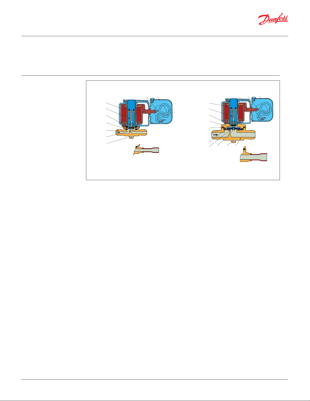
Design and Function
4. Coil
16. Armature
18. Valve plate/ Pilot valve plate
20. Ground terminal
28. Gasket
29. Pilot orice
40. Protective cap, Junction box
43. Valve cover
45. Valve cover gasket
49. Valve body
73. Equalization port
80. Diaphragm and servo piston
83. Valve seat
90. Mounting hole
© Danfoss | DCS (rja) | 2017.03
EVRH valves can only be used in
2
subcritical applications.
For CO
capacity tables, refer to Cool selector® or
2
contact your local Danfoss oce.
Direct operated
EVR 2 and EVR 3
EVRH solenoid valves are designed on two
dierent principles:
1. Direct operation
2. Servo operation
1. Direct operation
EVR 2 and EVR 3 are direct operated. The valves
open directly for full ow when the armature (16)
moves up into the magnetic eld of the coil. This
means that the valves operate with a min.
dierential pressure of 0 bar. The valve plate (18)
is tted directly on the armature (16). Inlet
pressure acts from above on the armature and
the valve plate. Thus, inlet pressure, and spring
force act to close the valve when the coil is
currentless.
2. Servo operation
EVR 4 to EVR 8 and EVRH 10 – EVRH 20 are servo
operated with a “oating” diaphragm (80). The
pilot orice (29) is placed in the centre of the
diaphragm. The pilot valve plate (18) is tted
direct to the armature (16). When the coil is
currentless, the main orice and pilot orice are
closed. The pilot orice and main orice are held
closed by the armature spring force and the
dierential pressure between inlet and outlet
sides. When current is applied to the coil the
armature is drawn up into the magnetic eld and
opens the pilot orice. This relieves the pressure
above the diaphragm, i.e. the space above the
diaphragm becomes connected to the outlet
side of thevalve.
Note: EVR 2-3 and EVRH 25-40 are not suitable for R744 (CO2)
applications with media temperatures constantly below 0 °C.
For other media temperatures, please contact Danfoss.
40
20
4
16
18
29
45
43
73
83
80
90
49
Danfoss
32F9025.10
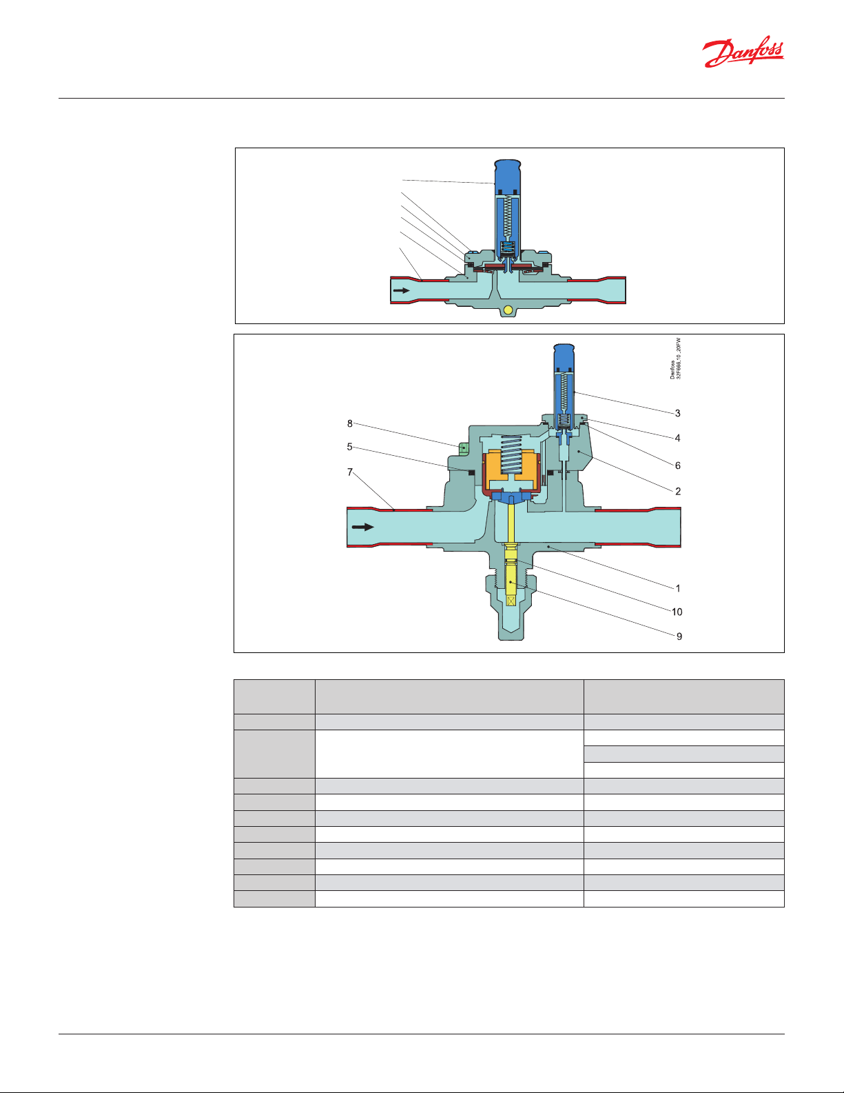
Servo operated
EVR 4 to EVR 8 and EVRH 10 to EVRH 40
The dierential pressure between inlet and
outlet sides then presses the diaphragm away
from the main orice and opens it for full ow.
Therefore a certain minimum dierential
pressure is necessary to open the valve and
keep it open. For EVR 4 to EVR 8 and EVRH 10
– EVRH 20 valves this dierential pressure is
0.05 bar. When current is switched o, the pilot
orice closes. Via the equalization holes (73) in
the diaphragm, the pressure above the
diaphragm then rises to the same value as the
inlet pressure and the diaphragm closes the
main orice.
EVRH 25 – EVRH 40 are servo operated piston
valves. The valves are closed with currentless
coil. The servo piston (80) with main valve plate
(84) closes against the valve seat (83) by means
of the dierential pressure between inlet and
outlet side of the valve and the force of the
compression spring (76).
When current to the coil is switched on, the
pilot orice (29) opens. This relieves the
pressure on the piston spring side of the valve.
The dierential pressure will then open the
valve. The minimum dierential pressure
needed for full opening of the valves is 0.2 bar.
DKRCC.PD.B00.C3.22 | 7
Page 8
32F665.10.20FW
Data sheet | Solenoid valves for R410A and R744 (CO2), EVR 2 to EVR 8, EVRH 10 to EVRH 40
Material specications
EVR 2 – EVR 8 and EVRH 10 – EVRH 25
3
8
2
5
1
7
Danfoss
© Danfoss | DCS (rja) | 2017.03
No. Description Material
1 Valve body Brass
2 Cover
3 Armature tube Stainless steel
4 Armature tube nut Stainless steel
5 Gasket Rubber
6 Gasket Al. gasket
7 Solder tube Copper
8 Screws Stainless steel
9 Spindle for man. operat. Stainless steel
10 Gasket Rubber
Stainless steel
Brass
Cast iron
DKRCC.PD.B00.C3.22 | 8
Page 9

32G1062 FW
Data sheet | Solenoid valves for R410A and R744 (CO2), EVR 2 to EVR 8, EVRH 10 to EVRH 40
Material specications
(continued)
EVRH 32 – EVRH 40
57 4
3
6
2
8
1
No. Description Material
1 Valve body Cast Iron
2 Cover Brass
3 Armature tube Stainless steel
4 Armature tube nut Stainless steel
5 Gasket Rubber
6 Gasket Al. gasket
7 Solder tube Bi-metallic tube
8 Screws Stainless steel
Danfoss
© Danfoss | DCS (rja) | 2017.03
DKRCC.PD.B00.C3.22 | 9
Page 10
Data sheet | Solenoid valves for R410A and R744 (CO2), EVR 2 to EVR 8, EVRH 10 to EVRH 40
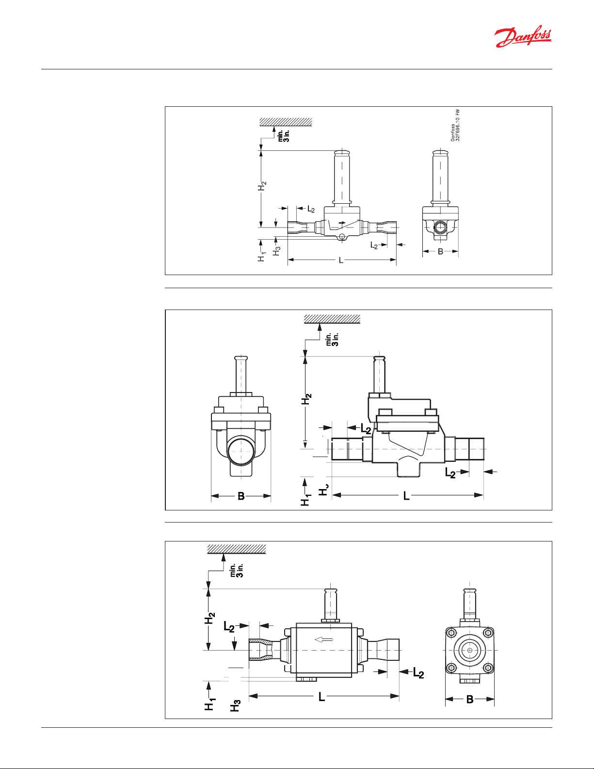
Dimensions and weight
EVR 2 – 6 and EVRH 10 – 20
Danfoss
EVRH 25
EVRH 32
Danfoss
Danfoss
© Danfoss | DCS (rja) | 2017.03
DKRCC.PD.B00.C3.22 | 10
Page 11
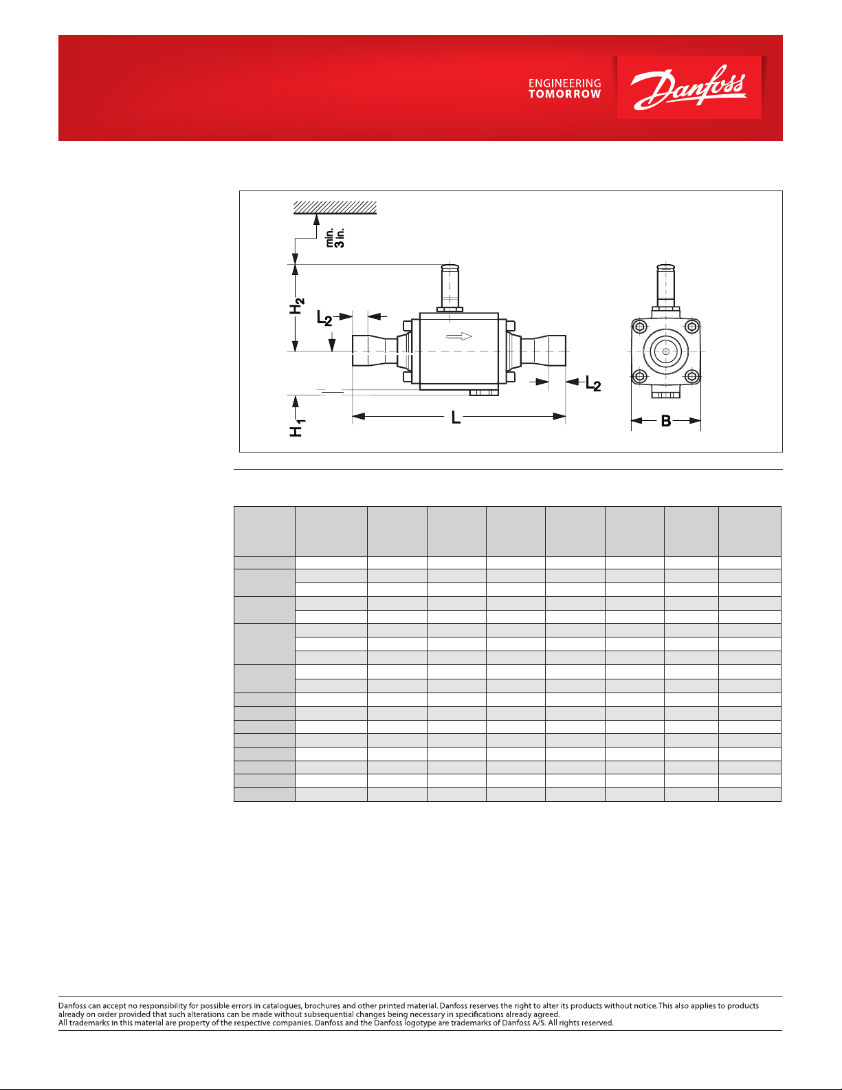
EVRH 40
EVRH 25, EVRH 32 – 40, solder connection
Danfoss
Type
connection
[in]
Solder
EVR 2 1⁄4 lbs
EVR 3
EVR 4
EVR 6
1
3⁄8
3
1⁄2
3⁄8
1
⁄4
⁄8
⁄2
5⁄8
EVR 8
1⁄2
5⁄8
EVRH 10 1⁄2 5⁄8 3
EVRH 15 5⁄8
EVRH 18 –
EVRH 20 7⁄8
EVRH 22
7
⁄8 25⁄32 3 7⁄16 – 7 1⁄2 5⁄8 2 13⁄16 –
EVRH 25 1 1⁄8 – 5 1⁄8 1 1⁄2 8 1⁄8
EVRH 32 – – 1 1⁄16 2 9 1⁄2
H1
[in]
9
⁄16 2 1⁄2 5⁄16 4
9
⁄16 2 1⁄2 5⁄16 4 9⁄32 1 5⁄16 0.44
9
⁄16 2 1⁄2 5⁄16 4 5⁄8
9
⁄16 2 3⁄4
9
⁄16 2 3⁄4
9
⁄16 2 3⁄4
9
⁄16 2 3⁄4
9
⁄16 2 3⁄4
9
⁄16 2 3⁄4
9
⁄16 2 3⁄4 3⁄8 6
3
⁄4 3 1⁄4 – 6 15⁄16 1⁄2 2 3⁄16 1.76
3
⁄4 3 1⁄4 – – – 2 3⁄16 –
25
⁄32 3 7⁄16 – 7 1⁄2 5⁄8 2 13⁄16 2.20
H
[in]
2
H
3
[in]
3
⁄8 4 1⁄4 5⁄16 1 5⁄16 –
3
⁄8 5 3⁄8 1 5⁄16 –
3
⁄8 4 1⁄4 5⁄16 1 5⁄16 0.66
3
⁄8 5
3
⁄8 6
3
⁄8 5
7
⁄16 5
L
[in]
L2
[in]
9
⁄32 1 5⁄16 0.44
5
⁄16 1 5⁄16 0.44
3
⁄8 1 5⁄16 0.66
1
⁄2 1 5⁄16 0.66
3
⁄8 1 5⁄16 –
1
⁄2 1 5⁄16 –
3
⁄8 1 13⁄16 1.10
7
⁄8 3 3⁄4 3.0
11
⁄16 3 1⁄8 4.3
B
[in]
EVRH 40 1 5⁄8 – 1 1⁄16 2 1⁄16 10 1⁄4 1 1⁄8 3 1⁄8 4.3
Net weight of coil: 0.67 lbs
Weight
[lbs]
© Danfoss | DCS (rja) | 2017.03 DKRCC.PD.B00.C3.22 | 11
 Loading...