

Page 1
Service on Household
Compressors
Refrigerators and Freezers
Using New Refrigerants
April 1996 CN.73.C3.02 1
Page 2
Replaces CN.73.C2.02
1.0 Introduction
1.1 Blends
(mixtures of HFC)
1.2 R134a (HFC)
1.3 R600a (Hydrocarbon)
2.0 General
Within a foreseeable future , CFC refrigerants will become unobtainable . This is a situation that will
effect the service possibilities on R12 systems in household appliances. In new production of
household appliances R12 will be replaced by R134a or R600a.
Please note that this guide excludes service on commercial appliances.
Since the introduction of R134a, several “transitional substances” have appeared. They have a
low ODP number and are intended for service only.
These refrigerants are interesting because they do not presuppose the use of polyolester oil.
To ensure a satisfactory miscibility between refrigerant and oil, the application of R134a refrigerant
presupposes the use of an R134a compressor charged with polyolester (POE).
This will complicate the future servicing when R12 refrigeration systems are to be changed over to
R134a refrigerant, as it is difficult to prevent contamination b y residues of the original refrigeration
oil, typically mineral oil or alkyl benzene.
The presence of residual mineral oil or alkyl benzene is unfortunate because it does not become
part of the R134a/POE mixture but circulates independently through the system. The eff ect can be
negative if the system contains “oil pockets”. After some time, the oil circulating in the system can
collect in quantities which pass through the capillary tube relatively slowly. This will effect the
refrigerant injection into the evaporator momentarily.
This refrigerant is flammable and only allowed for use in appliances which fulfil the safety requirements laid down in amendment TS 95006 to IEC 335 - 2 - 24 (To cover potential risk originated
from the use of flamable refrigerants).
In principle there is no need to replace the refrigerant in operational hermetic refrigeration systems. Neither is there any point in replacing refrigerant when servicing, provided that the original
refrigerant is available either as new or reclaimed. A precondition here is of course that the legislation of the country concerned is not restrictive in this respect.
Changing over to an alternative refrigerant is not without problems. Close consideration should be
given to the economic justification of proceeding with the task. It is also appropriate to find out just
what the user expects in terms of the operation and lifetime of the repaired system.
The choice of refrigerant for servicing R12 systems is between the transitional substances (blends)
or R134a.
Among the refrigerant mixtures offered are R401A and R401B which are marketed by DuPont.
These blends are ternary mixtures (non-azeotropes) made of three single components, R22, R152a,
and R124. Corresponding mixtures are also marketed by Atochem, R409A (Forane FX 56) and
R409B (Forane FX57). They are based on the components R22, R142B, and R124 (table 1). The
mixtures are interesting because they do not presuppose the use of polyolester compressor oil.
They have a low ODP number and can be used for service when R12 refrigerant is prohibited.
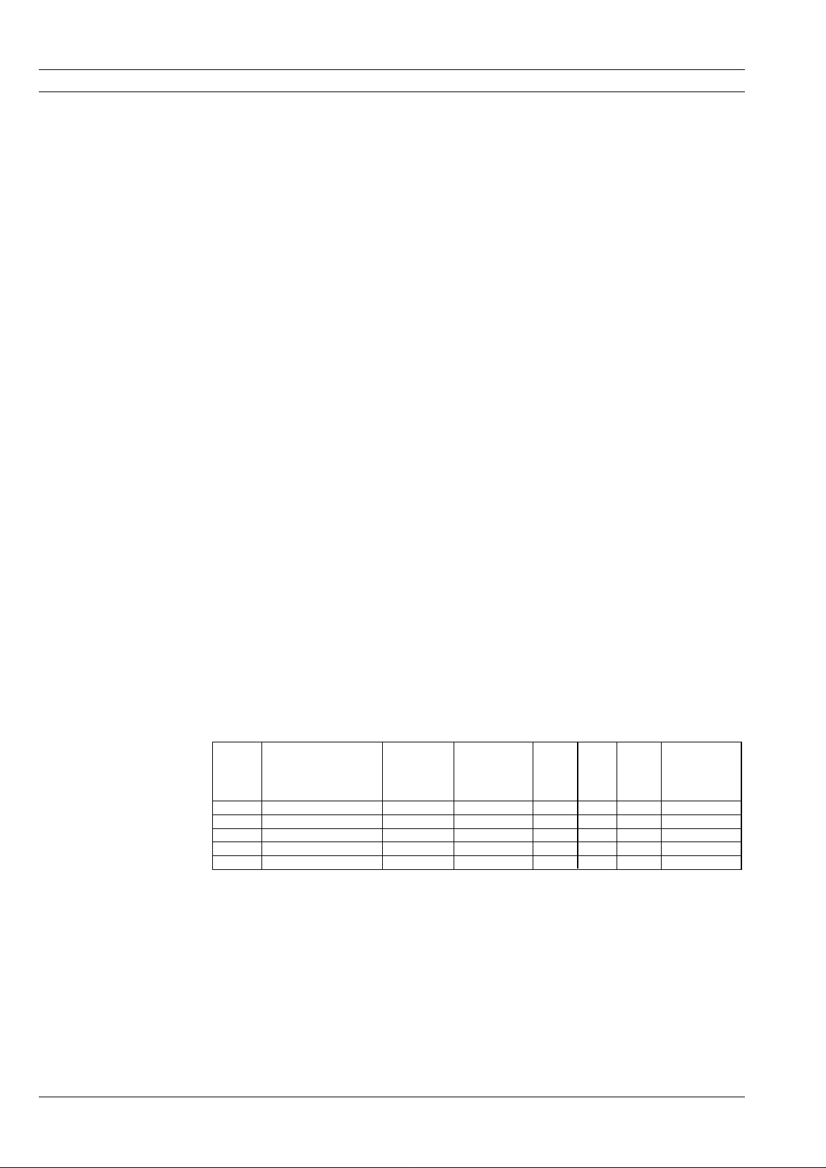
ASHRAE
No.
R401A R22 - R152a - R124 53 - 13 - 34 Suwa MP39 0.03 0.22 6.4 Alkyl benzene
R401B R22 - R152a - R124 61 - 11 - 28 Suwa MP66 0.035 0.24 6.0 Alkyl benzene
R409A R22 - R142B - R124 60 - 15 - 25 Forane FX56 0.05 0.31 8.1 Alkyl benzene
R409B R22 - R142B - R124 65 - 10 - 25 Forane FX57 0.05 0.31 7.2 Alkyl benzene
R134a 0.0 0.28 0.0 Ester oil
Table 1. Refrigerants for servicing R12 systems
Components Composition%Trade name ODP GWP Temp.
glide
Oil type
2 CN.73.C3.02 April 1996
Page 3
2.1 Servicing with blends The blends mentioned can be used for servicing, provided the following rules are observed,
The original compressor can be used, provided that it is intact. But the compressor oil must
be of the type alkyl benzene.
If the original compressor contains mineral oil it has to be changed to alkyl benzene. The
alkyl benzene must have more or less the same viscosity as the original oil.
A viscosity of about 30 cSt is a suitable choice for household refrigeration compressors.
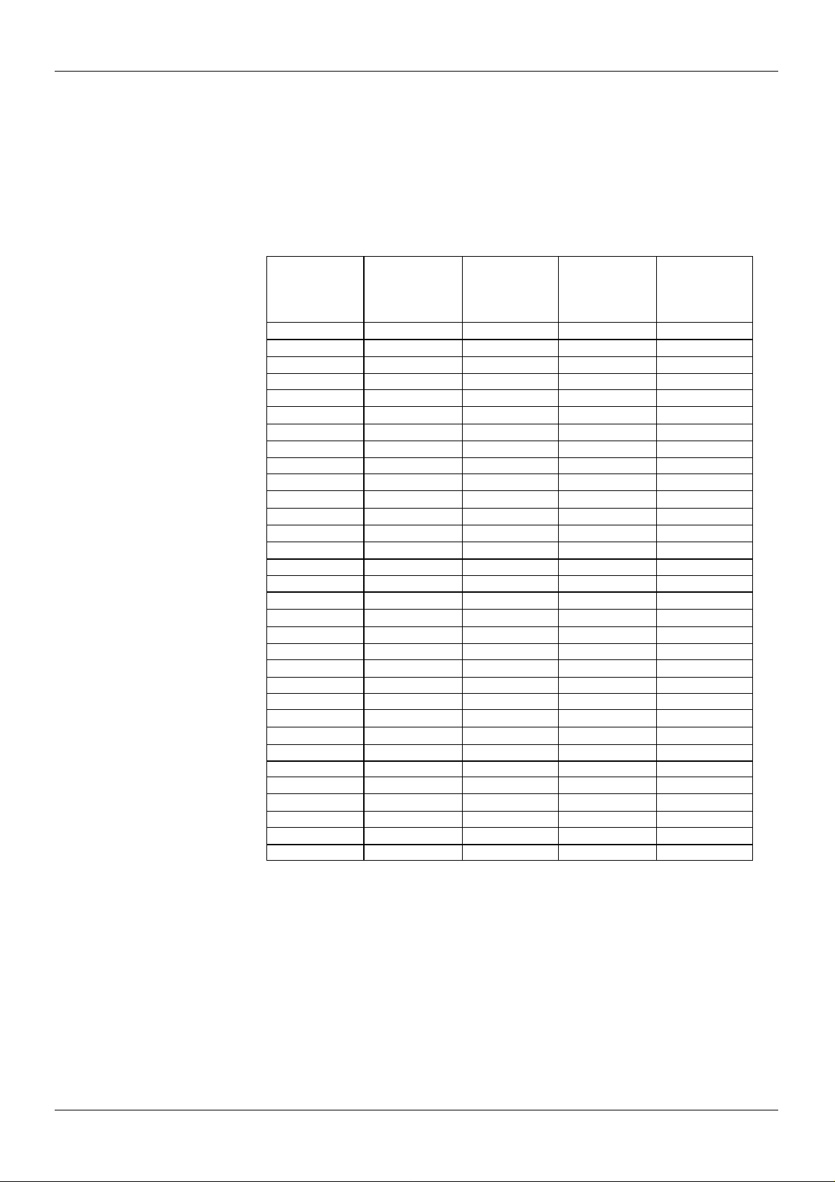
Table 2 shows the oil types used in Danfoss compressors.
Compressor type Compressor
V
TL-A 115 2 - 4 Synthetic Unchanged
TL-A 220 2 - 4 Mineral Alkyl benzene
TL-A 220 5 Synthetic Unchanged
TLS-A 220 4 Mineral Alkyl benzene
TLS-A 220 5 Synthetic Unchanged
TLES-A 220 4 Mineral Alkyl benzene
TLES-A 220 5 Synthetic Unchanged
TFS-A 115 4 - 5 Synthetic Unchanged
TFS-AT 220 4 - 5 Synthetic Unchanged
TF-B 115 4 Synthetic Unchanged
TL-B 220 2.5 - 3 Mineral Alkyl benzene
TL-B 220 4 Synthetic Alkyl benzene
NLE-A 115 6 - 7 Synthetic Unchanged
NF-A 115 6 Synthetic Unchanged
NL-A 220 6 - 7 Mineral Alkyl benzene
NLE-A 230 6 - 7 Mineral Alkyl benzene
FR-A 115 7.5 - 8.5 Mineral Alkyl benzene
FR-A 220 7.5 - 10 Mineral Alkyl benzene
FR-A 220 11 V-Oil 7041 Unchanged
FF-AT 220 6 - 10 Mineral Alkyl benzene
FFS-A 115 7 - 9 Mineral Alkyl benzene
FF-BK 115 6.5 - 8.5 Mineral Alkyl benzene
FF-BX 115 6.5 - 8.5 Mineral Alkyl benzene
FR-B 220 6 - 11 Mineral Alkyl benzene
FR-H 220 7 V-Oil 7041 Unchanged
SC-A 115 12 - 15 Mineral Alkyl benzene
SC-A 220 12 - 15 Mineral Alkyl benzene
SC-A 220 18 - 21 V-Oil 7041 Unchanged
SC-AA 240 15 V-Oil 7041 Unchanged
SC-B 115/220 10 - 2 1 V-Oil 7041 Unchanged
SC-H 220 10 - 15 V-Oil 7041 Unchanged
SC-HH 220 10 - 15 V-Oil 7041 Unchanged
displacement
3
cm
Present oil type Oil type for blendVoltage
Table 2. Oil types
If the original compressor is defective, the choice is between an R12 compressor and an R134a
compressor. The refrigeration capacity should be about the same as that of the original compressor. The R12 compressor oil must be changed over to alkyl benzene oil, provided that the original
oil charge was mineral oil. The R134a compressor can be used directly charged with polyolester
oil.
The filter drier must always be replaced. The new filter drier must contain a desiccant of the type
XH9 (UOP) or Siliporite H3R (CECA)
The system components, especially the evaporator, will always contain some oil transferred from
the original compressor. This is not critical if the new compressor contains alkyl benzene. But if a
compressor containing polyolester is to be used, residues in the original oil must be kept to the
lowest possible.
April 1996 CN.73.C3.02 3
Page 4

Normally, the limit is 10% of the original oil charge.
To ensure that the system is charged with a refrigerant mixture of the correct composition, the
charge should be led to the charging device or charging valve as liquid.
The blends in table 1 are non-azeotropes. Therefore the composition changes during evaporation and
condensation. This leads to temperature changes at
constant pressure.
This condition is called “temperature glide”. The extent of the temperature glide for the actual blends is
given in table 1.
Fig. 1 shows a pressure - enthalpy diagram for nonazeotropic refrigerants. A temperature rise occurs
from point “D” (inlet evaporator) to point “A” (outlet
evaporator).
This phenomenon can result in a different temperature distribution in the appliance compared to the
distribution with R12. The temperature at the outlet
of the evaporator will always be higher than the tem-
Fig. 1 Pressure - enthalpy diagram
perature at the inlet of the evapor ator . The diff erence
corresponds with the temperature glide shown in ta-
ble 1.
The influence of the storage temperature depends on the design of the refrigerating circuit and the
location of the thermostat bulb.
2.2 Servicing with R134a
Even though the use of the “service blends” gives the least complicated procedure, the possibility
of R134a is worth considering.
The main problem when changing from R12 to R134a is the oil problem. Any mixing with oil residues
will give a negative influence on the function of the system, as described in the introduction.
The preconditions for changing over to R134a are:
The compressor must be replaced with an original R134a compressor filled with an approved polyolester oil.
The filter drier must be replaced with a new drier containing desiccant of the type XH7
(XH9) or Siliporite H3R (CECA).
Oil residues in the system components must be kept on the lowest possible level. Up to 5%
residues in the total oil charge can be accepted.
Small hermetic systems are sensitive because of the use of capillary tube as the throttling
device.
Therefore the aim is to achieve a still smaller content of residual oil.
The oil residues in household refrigeration systems are normally lower than 5% of the total oil
charge. A bigger quantity may occur if the system contains oil pockets. If so it will be necessary to
clean the system by carefully blowing out each component with dry N2.
4 CN.73.C3.02 April 1996
Page 5

2.3 Servicing with R600a
R600a is a hydrocarbon. This refrigerant is flammable and is only allowed for use in appliances
which fulfil the requirements laid down in amendment TS 95006 to IEC 335 - 2 - 24 (To cover
potential risk originated from the use of flammable refrigerants). Consequently, R600a is only
allowed to be used in household appliances which are designed for this refrigerant and fulfil the
above-mentioned standard.
R600a is heavier than air. The concentration will always be highest at floor level.
The explosion limits are as follows,
Lower limit: 1.5% by vol. (38 g/m3)
Upper limit: 8.5% by vol. (203 g/m3)
Ignition temperature: 460°C
2.3.1 General
2.3.2 Transportation of
refrigerant and
replaced compressors
2.3.3 Tools
In order to carry out service and repair on R600a systems the service personnel must be properly
trained to be able to handle a flammable refrigerant. This includes knowledge on tools, tr ansportation of compressors and refrigerant, and the relevant regulations and safety precautions when
carrying out service and repair.
Warning: Do not use open fire.
The refrigerant must be stored and transported in approved containers. Max 2 x 500 g refrigerant
is allowed to be transported in a service car.
Replaced compressors containing refrigerant residues must be sealed before being transported.
In general: No open fire when troubleshooting and repairing.
The refrigeration circuit must be opened with a tube cutter or a special tool.
For tube connections, traction-stable compression fittings (e.g. socalled lockrings) must be used.
Vacuum pumps must be explosion-safe. It must be possible to lead the discharge air from the
vacuum pump into open air.
Leak detection cannot take place with normal halogen leak detectors, as they do not react on
hydrocarbons. A special detector reacting on hydrocarbon must be used instead. Another possibility is to use a leak spray.
Both solutions presuppose that the
vapour pressure in the system is
higher than 1 bar. Fig. 2 shows the
saturated vapour pressure as a function of the temperature.
The pressure is lower than the
normal atmospheric pressure below
-11°C. Accordingly it is necessary to
increase the pressure in the system
in order to carry out a leak detection.
This can be done by adding dry
nitrogen until a pressure of max 10
Fig. 2 Saturated vapour pressure, R600a
bar has been reached. Then the leak
detection can be carried out either
using a leak detector for R600a or a
leak spray.
April 1996 CN.73.C3.02 5
Page 6

Repair and refrigerant replacement of R12 systems
Guide
Troubleshooting
System defective
compressor intact
System leakage
1
If the system has lost charge, the leakage
must be localised and repaired.
Recover refrigerant
2
Fit a service valve, preferably on the process tube, and recover the system refrigerant charge. Equalise to atmospheric pressure using dry N
Replace filter drier
3
.
2
Remove the filter drier. Blow the system
components through with dry N
the system. Fit a new filter drier containing desiccant XH9 or H3R.
Oil change (if necessary)
4
If the original compressor is charged with
alkyl benzene it can be used unchanged.
If it has been charged with mineral oil, this
should be drained out in the best way possible. If necessar y, detach the compressor from the system before pouring out the
oil. Measure the collected oil in a gauge
glass.
Note: In connection with small compressors, some of the oil charge remains in the
motor windings and on the surfaces. Collected oil (and recovered refrigerant) must
be treated as special waste.
Refill the compressor with alkyl benzene
in the same quantity as the collected mineral oil. Refit the compressor into the system.
Evacuation and charging
5
Evacuate and charge the refrigeration system with service blends. Fill the refrigerant mixtures as liquid. Because the optimum service blend charge is less than the
original R12 charge, it is recommended
that filling be started using about 75% of
the original charge. The system can then
be gradually filled until it is in balance.
End of system repair
6
Close the process tube. Check for leakage. Run the system. Mark the system with
repair date, refrigerant type and amount,
and oil type in the compressor.
Blends selected
as refrigerant
. Repair
2
System defective
compressor defective
Recover refrigerant
1
Fit a service valve on the process tube and
recover the refrigerant. Equalilise to atmospheric pressure using N
Remove the compressor and the filter drier
2
.
2
Blow the system through with dry N2.
Compressor selection
3
Select a replacement compressor - either
an Rl2 compressor charged with alkyl benzene oil or an R134a compressor charged
with polyolester oil. The refrigeration capacity of the new compressor must correspond to that of the orginal compressor.
Fit new compressor and filter drier
4
Fit the new compressor . Fit a ne w filter drier
containing UOP XH9 or Siliporite H3H.
Evacuation and charging
5
Evacuate and charge the refrigeration system with the service blend. Fill the refrigerant mixtures as liquid. Because the optimum service blend charge is less than the
original R12 charge, it is recommended that
filling be started using about 75% of the
original charge. The system can then be
gradually filled until it is in balance.
End of system repair
6
Close the process tube. Check for leakage.
Run the system. Mark the system with repair date, refrigerant type and amount, and
oil type in the compressor.
R134a selected
as refrigerant
System defective
compressor defective
1
Compressor damage
If the defect is due to a “burnt out”
compressor motor, the system must be
scrapped
2
System leakage
If the system has lost charge, the leakage
must be localised.
3
Recover refrigerant
Fit a service valve, preferably on the process tube, and recover the system refrigerant charge. Equalise to atmospheric pressure using dry nitrogen (N
4
Remove the compressor and the filter drier
).
2
Flush all system components through with
dry nitrogen (N
Note: It is important that residues of min-
).
2
eral oil or alkyl benzene be kept to the lowest possible level.
5
Compressor selection
Select the R134a replacement compressor (the original compressor cannot be
used with R134a). The refrigeration capacity of the new compressor must correspond
to that of the original compressor.
6
Fit new compressor and filter drier
Fit the new compressor. Fit a new filter
drier containing dessicant XH7, XH9 or
H3R.
7
Evacuation and charging
Evacuate and charge the system with
R134a. For LBP systems the optimum
R134a charge will be less than the original R12 charge. Therefore begin by filling
about 75% of the original R12 charge and
then adjust up gradually until the system
is in balance.
8
End of system repair
Close the process tube. Check for leakage. Run the system. Mark the system with
repair date, refrigerant type and amount.
6 CN.73.C3.02 April 1996
Page 7

Repair of refrigeration systems with R600a
Guide
Troubleshooting
Compressor
intact
Preparation
1
Stop the compressor.
Check for leakage
2
Fit a service valve on the process tube.
Increase the pressure in the system to max
10 bar by means of dry nitrogen (N
for leakage by means of a leak spray or
suitable leak detector.
Repair the system
3
Release pressure into open air by means
of a plastic tube. Repair the system. Fit a
new filter drier.
Warning: Do not use open fire .
Evacuation
4
Evacuate the system. The discharge from
the vacuum pump must be lead into the
open air.
Charging
5
Charge the system with R600a. As some
of the original charge is dissolved in the
oil, it is recommended that the charging is
started with about 90% of the original charging amount.
System check
6
Run the system and check the temperatures.
End of system repair
7
Close the process tube with a traction-stable compression fitting.
Warning: Do not use open fire.
Labelling
8
Mark the system with repair date. Place a
warning label on the compressor. The label must be in accordance with TS (IEC
335 - 2 - 24).
). Check
2
Compressor
defective
Release refrigerant
1
Fit a service valve on the process tube and
release the refrigerant into open air by
means of a plastic tube.
Safety evacuation
2
In order to ensure that the defective compressor does not contain R600a residues,
which may be a fire hazard when the compressor is scrapped, the system must be
evacuated.
The discharge from the vacuum pump
must be lead into the open air. Equalise to
atmospheric pressure using dry nitrogen
).
(N
2
Remove the compressor and the filter drier
3
Close the compressor connectors with rubber plugs. Thoroughly blow through the
system with dry nitrogen (N
Warning: Do not use open fire.
Compressor selection
4
).
2
Select a new R600a compressor. The refrigeration capacity must correspond to that
of the original compressor.
Fit new compressor and filter drier
5
Evacuation and charging
6
Evacuate and charge the system with
R600a. The charge must correspond to the
original charge. Start the compressor.
System check
7
Run the system and check the temperatures.
End of system repair
8
Close the process tube with a traction-stable compression fitting.
Warning: Do not use open fire.
Labelling
9
Mark the system with repair date. Place a
warning label on the compressor. The label must be in accordance with TS (IEC
335 - 2 - 24).
April 1996 CN.73.C3.02 7
Page 8

Danfoss can accept no responsibility for possible errors in catalogues, brochures and other printed material. Danfoss reserves the right to alter its products without notice. This also applies to
products already on order provided that such alterations can be made without subsequential changes being necessary in specifications already agreed.
8 CN.73.C3.02 April 1996
 Loading...