

Page 1
User Manual
Remote Control
R11 Receiver
www.danfoss.com
Page 2

User Manual
R11 Receiver
Revision history Table of revisions
Date Changed Rev
January 2019 Rebranded to Danfoss Power Solutions 0101
2 | © Danfoss | January 2019 BC293063716706en-000101
Page 3

User Manual
R11 Receiver
Contents
Safety instructions
Technical description
Installation
Troubleshooting
General safety.................................................................................................................................................................................... 4
Safety warnings.................................................................................................................................................................................4
Dimensions and identification.....................................................................................................................................................5
Receiver installation........................................................................................................................................................................ 6
Receiver LED troubleshooting guide........................................................................................................................................ 7
©
Danfoss | January 2019 BC293063716706en-000101 | 3
Page 4
Tx Cr 1
Cr 1
Remove the EEPROM in order
to disable the transmitter
When in doube, press the
STOP button
Make sure the transmitter
works with the machine
to be handled
Do not use the set when
visibility is limited
Avoid knocking or dropping
the set
User Manual
R11 Receiver
Safety instructions
R11 general safety
The following safety instructions must be read carefully in order to install and use the product properly
and to keep it in perfect working condition and to reduce the risk of misuse.
Potential damage to operator and product.
Do not use this product on machines in potentially explosive atmospheres unless the model is ATEX/
RATEX certified to do so.
•
Strictly adhere to the installation instructions contained in this document.
•
Make sure that professional and competent personnel carry out the installation.
•
Ensure that all site and prevailing safety regulations are fully respected.
•
Make sure that this document is permanently available to the operator and maintenance personnel.
•
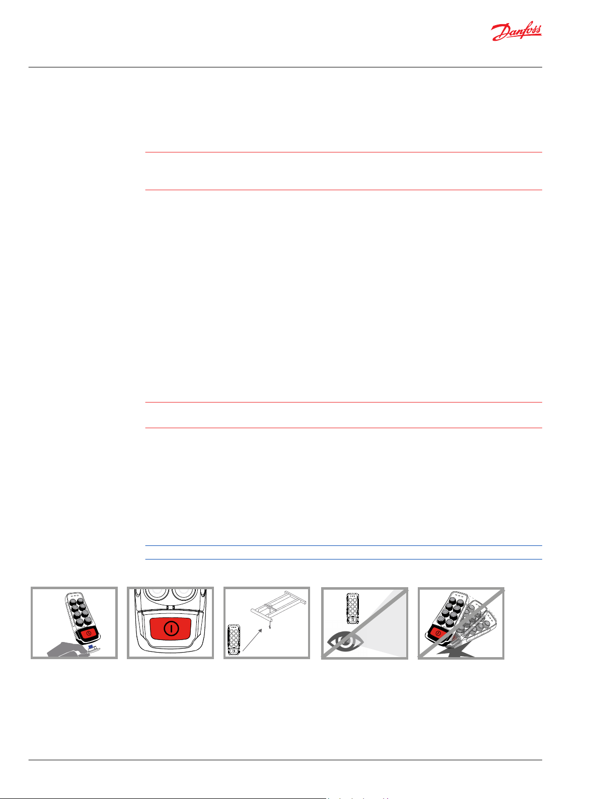
Keep the transmission key when the set is not in use.
•
On starting each working day, check to make sure that the STOP button and other safety measures
are working.
•
When in doubt, press the STOP button.
•
Whenever several sets have been installed, make sure the transmitter is the right one. Identify the
machine controlled on the label for this purpose on the transmitter or by using the display (in case it
has one).
•
Service the equipment periodically.
•
When carrying out repairs, only use spare parts from Danfoss.
R11 safety warnings
Quick reference precautions
Potential damage to operator and product.
Follow the guidelines below to reduce risk of injury to the operator and the product.
•
Use the device with the manufacturer's battery and battery charger (if applicable).
•
Only allow qualified personnel to operate the equipment.
•
Always set the STOP button in the off position when not in use.
•
Always press STOP before plugging in tether cable (if applicable).
•
Do not operate product when visibility is limited.
•
Make sure product is compatible with the machine.
•
Avoid knocking or dropping the product.
•
Do not use the product if a failure is detected.
Changes or modifications not approved by Danfoss can void the user's authority to operate this product.
4 | © Danfoss | January 2019 BC293063716706en-000101
Page 5

1
2
8
5
4
3
7
6
127.08
173.29
37.02
164
36.41
163.50
30 30
60
R 5.50
User Manual
R11 Receiver
Technical description
R11 dimensions and identification
Dimensions in mm
1. Fixing slots (fixed assembly or anti-vibration with magnets
*
2. M25 cable gland
3. Power supply
4. LR11 logic board
5. Removable EEPROM
6. Signaling LEDs
7. 2.4 GHz radio
8. Wiring connection
*
The use of the anti-vibration kit is recommended in any case
©
Danfoss | January 2019 BC293063716706en-000101 | 5
Page 6

User Manual
R11 Receiver
Installation
R11 receiver installation
Risk of shock
Completely shut down the machine when installing the receiver.
Check the power supply and shut off the main switch to disconnect the interface cable between the
receiver and the machine's electrical box.
1. Find an easily accessible and clear location with a direct vision between the receiver's antenna and
the transmitter's working area.
It is strongly advised to avoid installing the receiver inside a closed metal enclosure.
2. Optional: If high levels of vibration is expected, ensure shock-absorbers are being used.
3. Connect the power supply and the receiver's outputs using the connection block diagram provided
with the system.
4. Check the electrical installation and verify if there is an option to connect the neutral or the ground
cable. In that case, be sure to connect the ground cable.
To guarantee a reliable connection, apply a torque between 0.5 and 0.5 Nm to screw the connection
terminals.
6 | © Danfoss | January 2019 BC293063716706en-000101
Page 7

User Manual
R11 Receiver
Troubleshooting
Receiver LED troubleshooting guide
The troubleshooting LEDs are located on then receiver board. Use the following table to identify faults
and corrective action.
In order to reach the signaling, the receiver must be accessible and connected and the two screws
located on the base of the receiver must be released using the suitable tool.
The LEDs on the receiver board are POWER, STATUS, DIAG1, DIAG2, ORDER and RELAY in that order.
LED Color and frequency Pulse frequency Description Action
POWER Green | continuous Switched ON if powered Check power supply if it is
STATUS Blue | fast pulses System is starting; establishing connection with
radio and EEPROM
switched off.
Wait
STATUS +
DIAG1
Blue | continuous Waiting for transmitter communication, coming
Blue | slow pulses Waiting for transmitter communication, coming
Green | continuous Working Operate
Red | slow pulses EEPROM module missing or corrupt Check EEPROM and reprogram
Red | double pulses Radio communication error Replace receiver
Red | triple pulses Secondary micro error or error between micro
Red | 4 pulses
Orange | slow pulses
Red | 4 pulses
Orange | double pulses
from ACTIVE STOP
from PASSIVE STOP
communication
Low tension in the receivers power supply Supply the system with the
Hardware error Replace receiver
Release STOP button and press
START
Press Start
if necessary
Replace receiver
correct voltage
Red | 4 pulses
Orange | triple pulses
Red | 4 pulses
Orange | 4 pulses
©
Danfoss | January 2019 BC293063716706en-000101 | 7
Page 8

User Manual
R11 Receiver
Troubleshooting
LED Color and frequency Pulse frequency Description Action
DIAG1 Green | slow pulses Low link quality N/A
Green | double pulses Medium link quality N/A
Green | triple pulses High link quality N/A
ORDER Green | continuous N/A
RELAY Green | continuous STOP relay activated N/A
8 | © Danfoss | January 2019 BC293063716706en-000101
Page 9

User Manual
R11 Receiver
©
Danfoss | January 2019 BC293063716706en-000101 | 9
Page 10

User Manual
R11 Receiver
10 | © Danfoss | January 2019 BC293063716706en-000101
Page 11

User Manual
R11 Receiver
©
Danfoss | January 2019 BC293063716706en-000101 | 11
Page 12

Danfoss
Power Solutions GmbH & Co. OHG
Krokamp 35
D-24539 Neumünster, Germany
Phone: +49 4321 871 0
Danfoss
Power Solutions ApS
Nordborgvej 81
DK-6430 Nordborg, Denmark
Phone: +45 7488 2222
Danfoss
Power Solutions (US) Company
2800 East 13th Street
Ames, IA 50010, USA
Phone: +1 515 239 6000
Danfoss
Power Solutions Trading
(Shanghai) Co., Ltd.
Building #22, No. 1000 Jin Hai Rd
Jin Qiao, Pudong New District
Shanghai, China 201206
Phone: +86 21 3418 5200
Products we offer:
Comatrol
www.comatrol.com
Turolla
www.turollaocg.com
Hydro-Gear
www.hydro-gear.com
Daikin-Sauer-Danfoss
www.daikin-sauer-danfoss.com
DCV directional control
•
valves
Electric converters
•
Electric machines
•
Electric motors
•
Hydrostatic motors
•
Hydrostatic pumps
•
Orbital motors
•
PLUS+1® controllers
•
PLUS+1® displays
•
PLUS+1® joysticks and
•
pedals
PLUS+1® operator
•
interfaces
PLUS+1® sensors
•
PLUS+1® software
•
PLUS+1® software services,
•
support and training
Position controls and
•
sensors
PVG proportional valves
•
Steering components and
•
systems
Telematics
•
Danfoss Power Solutions is a global manufacturer and supplier of high-quality hydraulic and
electric components. We specialize in providing state-of-the-art technology and solutions
that excel in the harsh operating conditions of the mobile off-highway market as well as the
marine sector. Building on our extensive applications expertise, we work closely with you to
ensure exceptional performance for a broad range of applications. We help you and other
customers around the world speed up system development, reduce costs and bring vehicles
and vessels to market faster.
Danfoss Power Solutions – your strongest partner in mobile hydraulics and mobile
electrification.
Go to www.danfoss.com for further product information.
We offer you expert worldwide support for ensuring the best possible solutions for
outstanding performance. And with an extensive network of Global Service Partners, we also
provide you with comprehensive global service for all of our components.
Local address:
Danfoss can accept no responsibility for possible errors in catalogues, brochures and other printed material. Danfoss reserves the right to alter its products without notice. This also applies to products
already on order provided that such alterations can be made without subsequent changes being necessary in specifications already agreed.
All trademarks in this material are property of the respective companies. Danfoss and the Danfoss logotype are trademarks of Danfoss A/S. All rights reserved.
©
Danfoss | January 2019 BC293063716706en-000101
 Loading...